
ABSTRACT
This project, solar powered mobile phone charger is designed for use in mobile phones and other gadgets which uses a 5v input for charging. The circuit makes use of a microprocessor (LM256T-ADJ) to create a buck converter which steps down the voltage from the solar panel to suit the level of voltage needed by the mobile phone. The use of this charger guarantee’s the safety of mobile phones being charged as it is being charged in range and at one’s comfort
CHAPTER ONE (1)
INTRODUCTION
BACKGROUND OF THE STUDY
Portable Solar Mobile Phone Charger is a power electronic device that converts the sun’s radiation into electrical energy for the purpose of charging the batteries of mobile phones. It does this by converting, controlling and conditioning the flow of electrical energy from source (solar panel) to load (mobile phone) according to the requirements of the load.
In a densely populated, poverty-stricken country with a population of over 160 million people in the case of Nigeria, it is unarguable that the epileptic state of power supply is an issue of great concern to Nigerians. Citizens find it very difficult to charge their phones when they eventually have a flat battery. We are now left with the option of putting on a generating set (Generator) which causes air pollution and depletion of the atmospheric ozone layer (greenhouse effect), generators are also very expensive to operate due to the hike in price of petrol in the country. The option of charging through public charging centers is inconvenient as most times these centers are crowded and employ the use of a generator as well. Theft of mobile phones is prevalent with charging centers and fire outbreaks in many cases due to overload of supplying cables and very unprofessional connections done in order to realize money as quickly as possible.
1.2 STATEMENT OF THE PROBLEM
Most country are faced with many challenges ranging from air pollution due to smoke from some source of power supply. Lack of effective and reliable power supply system.
The epileptic and incessant power supply in Nigeria in this case Owerri imo state in particular has necessitated once need for this project, cause most student and people always on stand-alone generators to charge up their phone and appliances which can be charge using the USB ported solar charger.
So, there is a need to design and construct the solar panel charger which will complement the electricity supply from the public grid because the reduction injunctive and capacitive load. It is less noisy and does not have any consequence(s) on human health
1.3 AIMS AND OBJECTIVES
1.3.1 Aim:
The aim of this project is to design a cost effective solar powered mobile phone charger, which has a USB port and can also be used to charger other appliance with same input or charging mode
1.3.2 Objectives:
The following are specific objective
i. To design a portable solar charger.
ii. To construct the designed solar mobile phone charger.
iii. To evaluate the performance of the designed charge
1.4 SIGNIFICANCE OF THE STUDY
The project completion will be of great help to country if adopted, in order to maintain a stable power source for mobile phones in country. The use of solar power has advantages firstly the energy from the sun is free and readily accessible in most part of the world. More over the sun will keep shining until end. Also, silicon from which most photovoltaic cell are made is in abundant and nontoxic element. The whole energy conversion process is environmentally friendly.
It produces no-noise, harmful emission or polluting gases. The burning of natural resource of energy can create Smoke, cause acid rain and pollute water and air
CHAPTER TWO
LITERATURE REVIEW
2.1 RELATED WORK
A lot of research work has been carried out on the design of a cost-effective solar power charger. Engr Chinedu P.A Okwaraokwa, Engr Azubogu and Engr M.I Ariguzo researched on a cost effective solar charger controller for lithium ion battery using 555 time IC in 2016. in this work an 8 watt photovoltaic (PV) Panel successfully used to charge a lithium ion battery using a custom designed and constructed pulse width modulated(PWM) solar charge controller . The charger controller includes automatic cut off to prevent battery overcharge (international journal of electrical and telecommunication system research.
Anurag project a channel on you tube did similar work on the project on 2021, he used 1c78056x1, capacitor 1000ufx2, diode 1n 4007×1, resistor 1kx1 ledx1, USB female port connector x1 and a solar panel 6x2w to construct the project as shown in the diagram.
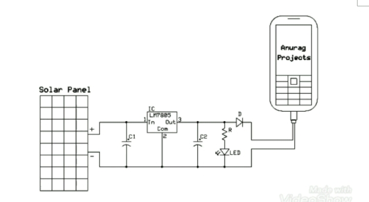
Figure 2.1
Design and construction of a portable solar mobile charger by salim mudi in the department of telecommunication engineering, federal university of technology, mina Nigeria (2018). The charger was made by converting, controlling and condition the flow of electrical energy from source to load according to the requirement of the load.
2.2 PROJECT ANALYSIS
2.2.1. Solar panel
Solar panels are devices that convert light into electricity. They are called “solar” panels because most of the time, the most powerful source of light available is the Sun, called Sol by astronomers. Some scientists call them photovoltaic’s which means, basically, “light-electricity”.
A solar panel is a collection of solar cells. Lots of small solar cells spread over a large area can work together to provide enough power to be useful. The more light that hits the cell, the more electricity it produces. Solar panels generate free power from the sun by converting sunlight to electricity with no moving parts, zero emissions, and no maintenance. The solar panel, the first component of an electric solar energy system, is a collection of individual silicon cells that generate electricity from sunlight. The photons (light particles) produce an electrical current as they strike the surface of the thin silicon wafers. A single solar cell produces only about 1/2 (.5) of a volt. Multiple solar panels can be wired in parallel to increase current capacity (more power) and wired in series to increase voltage for 24, 48, or even higher voltage systems. The advantage of using a higher voltage output at the solar panels is that smaller wire sizes can be used to transfer the electric power from the solar panel array to the charge controller & batteries Embark electronics.
The solar panel is made up of the following:
The semiconductor material which absorbs light and converts it into electron-hole pairs.
The junction formed within the semiconductor, which separates the photo-generated carriers (Electrons and holes).
The contacts on the front and back of the cell that allow the current to flow to the external circuit.
The glass sheet that protects the semiconductors and also prevent reflection of the sun rays.
The frame that holds the whole component together as one component.
The terminals where the generated direct current is tapped from.
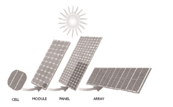
Figure 2.2.1 Shows Cell- Module- Panel- Array
Multiple modules can be wired together to form an array. In general, the larger the area of a module or array, the more electricity that will be produced. Photovoltaic modules and arrays produce direct-current (dc) electricity.
2.2.2 Types of Solar Panels
Basically, there are three basic types of solar panels and they include;
Monocrystalline Solar Panels
Polycrystalline Solar Panels
Amorphous solar panels
Monocrystalline Solar Panels: The most efficient and expensive solar panels are made with Monocrystalline cells. These solar cells use very pure silicon and involve a complicated crystal growth process. Long silicon rods are produced which are cut into slices of .2 to .4 mm thick discs or wafers which are then processed into individual cells that are wired together in the solar panel.
Polycrystalline Solar Panels: Often called Multi-crystalline, solar panels made with Polycrystalline cells are a little less expensive & slightly less efficient than Monocrystalline cells because the cells are not grown in single crystals but in a large block of many crystals. This is what gives them that striking shattered glass appearance. Like Monocrystalline cells, they are also then sliced into wafers to produce the individual cells that make up the solar panel.
Amorphous solar panels: These are not really crystals, but a thin layer of silicon deposited on a base material such as metal or glass to create the solar panel. These Amorphous solar panels are much cheaper, but their energy efficiency is also much less so more square footage is required to produce the same amount of power as the Monocrystalline or Polycrystalline type of solar panel.
2.2.3 Specifications Of Solar Panels
Solar panels have many specifications. The most important values are:
Peak Power
Open Voltage
Short Circuit Current
Peak Power
The peak power is the maximum power that a solar panel can give when it is being operated in full sunlight. The higher the peak power, the higher the energy output of the panel will be.
Open Voltage
The open voltage is the voltage which is measured when the panel is not connected to anything but a voltmeter and pointed to the sun. The open voltage can be used to determine whether is panel is positioned in the right way. The higher the open voltage, the higher the energy output of the panel will be.
Short Circuit Current
The short circuit is the current which is measured when the panel is not connected to anything but a current meter to measure the short circuit current. The higher the short circuit current, the higher the energy output of the panel will be.
2.2.4 Dc to Dc converter
A DC-to-DC converter is an electronic circuit or electromechanical device that converts a source of direct current (DC) from one voltage level to another. It is a type of electric power converter. Power levels range from very low (small batteries) to very high (high-voltage power transmission). DC-to-DC converters are used in portable electronic devices such as cellular phones and laptop computers, which are supplied with power from batteries primarily. Such electronic devices often contain several sub-circuits, each with its own voltage level requirement different from that supplied by the battery or an external supply (sometimes higher or lower than the supply voltage). Additionally, the battery voltage declines as its stored energy is drained. Switched DC to DC converters offer a method to increase voltage from a partially lowered battery voltage thereby saving space instead of using multiple batteries to accomplish the same thing.
Most DC-to-DC converter circuits also regulate the output voltage. Some exceptions include high-efficiency LED power sources, which are a kind of DC to DC converter that regulates the current through the LEDs, and simple charge pumps which double or triple the output voltage.
2.2.5 TYPES OF DC TO DC CONVERTERS
Buck converter
Boost converter
A buck converter (step-down converter) is a DC-to-DC power converter which steps down voltage (while drawing less average current) from its input (supply) to its output (load). It is a class of switched-mode power supply (SMPS) typically containing at least two semiconductors (a diode and a transistor, although modern buck converters frequently replace the diode with a second transistor used for synchronous rectification) and at least one energy storage element, a capacitor, inductor, or the two in combination. To reduce voltage ripple, filters made of capacitors (sometimes in combination with inductors) are normally added to such a converter’s output (load-side filter) and input (supply-side filter). It is called a buck converter because the voltage across the inductor “bucks” or opposes the supply voltage. Switching converters (such as buck converters) provide much greater power efficiency as DC-to-DC converters than linear regulators, which are simpler circuits that lower voltages by dissipating power as heat, but do not step up output current. The efficiency of buck converters can be very high, often over 90%, making them useful for tasks such as converting a computer’s main supply voltage, which is usually 12 V, down to lower voltages needed by USB, DRAM and the CPU, which are usually 5, 3.3 or 1.8 V.
CHAPTER THREE
MATERIALS AND METHOD
3.1 MATERIALS
The following materials were used for the construction, for this project to be completed there is a need to know the component to be used for the design these includes:
Solar panel
Universal serial bus connector
Vero board
16v 1500uf capacitor x6
Buck converter materials:
LM256T-ADJ x1
IN5822 diode x1
Capacitor 100uf x1
Electrolytic capacitor 2200uf x1
Inductor 150uh x1
Potentiometer 47k x1
Through hole resistor 1.2k ohms x1
3.2METHOD
Circuit diagram:
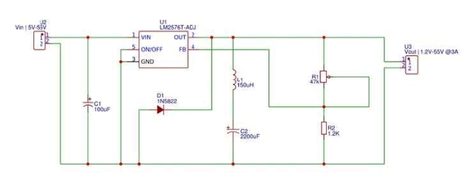
Figure 2.1.2 : showing the circuit diagram of project
3.3 SYSTEM OPERATION
The solar panel absorbs energy produced by the sun and converts it into electrical energy. It does this by absorbing sun rays into the modulus of solar panel hence produce free electrical charge carriers in the conduction and valence bonds. The electricity produced by the solar panel is DC and it is transferred to the capacitor, due to variation in intensity of sunlight to avoid lower or higher voltage which would damage our circuit or device the capacitors are added to store up the charge acting as a battery to provide a steady voltage at input. The input charge is transferred to the buck converter, the buck converter makes use of LM2576T-ADJ microprocessor and it has feedback and output will stay the same using different loads, with it we have feedback pin connected to output voltage divider, the LM256T-ADJ will change the width of the pulse depending on the output in other to keep the output constant. In this project we used a Schottky barrier rectifier diode because it has a load forward voltage; this diode will allow the current to flow when the microprocessor switch is open
3.4 DESIGN CALCULATION
Capacitors:
A capacitor is an electrical device that can store charge or energy. Capacitors can be connected in two ways namely:
Serial capacitor connection.
Parallel capacitor connection.
When capacitors are connected in series the amount of charge output is the addition of the reciprocal of each capacitors charge and the voltage across them is not the same, there is voltage drop across each capacitor
CT = 1/c1 + 1/c2 + 1/c3
Total v = v1 + v2 + v3
In a parallel connection the amount of output charge is the addition of individual charge of each capacitor. The voltage in this type of connection is the same across each capacitor.
CT= C1 + C2 + C3
Total v = v1 = v2 = v3
Therefore, total charge in capacitor = 1500uf x 6 = 9000uf
Voltage =16v
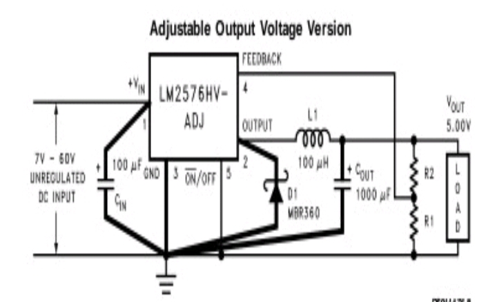
LM2576T-ADJ
The lm2567-adj regulators are monolithic integrated circuit that provides all the active functions of a step-down (buck) switching regulator capable of driving 3A load with excellent line and load regulation.
The LM2576T-ADJ description
Maximum supply voltage = 45V
On/off pin input voltage -0.3v =< V = < +V in
Output voltage to ground
(Steady state). -1V
Power dissipation internally limited
Maximum junction temperature. 150°C
vout = vref(1+R2/R1)
R2 = R1(vout /vref -1)
Where Vref = 1.23v
R1 is between 1k to 5k ohms
When Vout = 5v
Vin = 18v
R1 = 1.2kohms
R2 which is the potentiometer is set to
R2 = 1.2×10³ (5/1.23 – 1)
= 3.68k ohms
I load (max) = 3.0A
So the potentiometer will be set to 3.6k for there to be a 5v output for charging the gadget
Inductor
An inductor is a passive electronic component that stores energy in the form of a magnetic field. In its simplest form, an inductor consists of a wire loop or coil. The inductance is directly proportional to the number of turns in the coil. we used the induction selection guide in figure below to select the inductance of the inductor
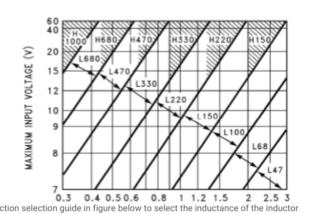
From the figure above the inductance of inductor needed is L100
Output capacitor
A capacitor of capacitance ranging from 680uf to 2200uf is used at the output , the capacitor should be a standard aluminum electrolytic capacitor. The voltage rating should be 20V .
Input capacitor
A 100uf 25v aluminum electrolytic capacitor is located near the input and ground pin , it provides sufficient bypassing
Catch diode
The buck regulator requires a diode to provide a return path for the inductor current when switch is off. Thus, this diode should be located close to the lm2576t-adj using short leads. Because of their fast switching speed and low forward voltage drop, schottky diodes provide the best efficiency for the project. An in5822 diode was selected.
The voltage of the solar panel increases when exposed to sunlight with respect of time of explosion. Similar, applies to the current and electrical power produced.
If you find this post helpful, please share it and spread the word!
Related blog
→ PROJECT WRITE-UP FOR FABRICATION AND INSTALLATION OF WORKSHOP METAL DOOR 2022
Siwes report on computer engineering – free write-up→
HOW TO WRITE A TECHNICAL REPORT ON STUDENT INDUSTRIAL WORK EXPERIENCE SCHEME (SIWES)