
CHAPTER ONE
INTRODUCTION
1.1 BACKGROUND OF STUDY
Electricity could be said to be one of the greatest inventions of man. This is because many other inventions and processes depend on it for proper functioning. The most common source of this important energy is the utility lines that come from hydroelectric power stations. However, the AC supply from utility lines is subject to power surges, voltage shortage, complete power failure and wide variations in the electric current frequency. The epileptic and unreliable power supply by the authority in Nigeria, especially in recent times, is a major issue of concern to every well-meaning Nigerian. The need for a constant supply of electricity has always been the priority of the power authority yet they cannot boast of supplying power constantly for a running day. Due to such, a need arose for the design and construction of the Uninterrupted Power Supply (UPS).
For ordinary household appliances such as incandescent lamps, heaters, fans and fridges, the common mains ac supply could be used casually, that is, without giving thought to its inherent shortcomings, because the performance of these appliances are seldom affected by power variations or interruptions. This is not the case with sophisticated and sensitive electronic instruments/equipment such as computers, medical equipment and telecommunication systems which require a stable and interruption free power supply.
Uninterruptible Power Supply (UPS) is an electrical apparatus that provides emergency power to a load when the input power source, typically mains power, fails. It provides near-instantaneous protection from input power interruptions, by supplying energy stored in batteries. The on-battery runtime of most uninterruptible power sources is relatively short (only a few minutes) but sufficient to start a standby power source or properly shut down the protected equipment.
The energy crisis affecting small and medium scale industries and light household loads can effectively be addressed by devising methods of energy storage which could be used during short-period power outage or using a generator which is very costly to maintain. An absolute solution to energy demand can be achieved by adoption of renewable energy development especially the abduction of charge inverter.
The inverter makes use of an energy source such as photovoltaic to be domestically and industrially relevant for use, as in short goes a long way to reduce the level of greenhouse gases in the atmosphere and alleviate this global warming on process. The photovoltaic power generation is reliable. It involve no moving parts and the operation and maintenance cost are very low (Coker and Ogungi, 2013).
Electricity generation is the first process in the delivery of electrical power to consumer. The other processes are electricity transmission and distribution. The importance of electricity generation was revealed when it became apparent that electricity generation was useful for producing heat, light and power for human needs.
An inverter converts the DC voltage to an AC voltage, In most cases, the input DC voltage is usually lower while the output AC is equal to the grid supply voltage of either 120 volts or 240 volts depending on the country.
The inverter may be built as standalone equipment for applications such as solar power or to work as a backup power supply from batteries which are charged separately.
The other configuration is when it is a part of a bigger circuit such as power supply unit or a UPS. In this case, the inverter input DC is from the rectifier mains AC in the UPS, while from either the rectifier AC in the UPS when there is power and from the batteries whenever there is a power failure.
There are different types of inverters based on the shape of the switching waveform. These have varying circuit configuration, efficiencies, advantages and disadvantages.
An inverter provides an AC voltage from DC power sources and is useful in powering electronics and electrical equipment rated at the AC mains voltages. In addition they are widely used in the switched mode power supplies inverting stages. The circuits are classified according to the switching technology and switch type, the waveform, the frequency and output waveform.
1.2 STATEMENT OF THE PROBLEM
Unexpected power disruption in homes, offices and industries could cause injuries, fatalities, serious business disruption or data loss. Of the myriad of devices, processes and systems which rely on AC power, computers are the most sensitive to power disturbances and failures. Interruptions in power supply may cause the contents of a memory to be lost or corrupted, the entire system to malfunction or fail, or even variety of components failures to occur, all of which not only result in inconvenience but also loss of money. The problems can be summarized thus:
I. Unexpected power disruption could cause the malfunction of certain life support equipment used in hospitals which may result in injury or even death.
II. In telecommunication and data centers, an unexpected power disruption could cause hardware malfunction, data loss or temporary closure of business, all of which incur greater expenses to the business owner.
III. In homes and small offices, unexpected power disruption cause malfunction and memory loss in personal computers which result in loss of time, energy and money.
The power disruptions could be any of the following:
I. Voltage spike or sustained over voltage.
II. Momentary or sustained reduction in input voltage.
III. Noise, defined as a high frequency transient or oscillation, usually injected into the line by nearby equipment.
IV. Instability of the mains frequency.
V. Harmonic distortion, defined as a departure from the ideal sinusoidal waveform expected on the line.
1.3 RESEARCH OBJECTIVE
The following are the main objective of this project,
To understand the appropriate circuit diagram for the construction.
To test the functionality of the constructed project.
A backup power supply system which is eco friendly
To provide a noiseless and weightless source of electricity supply.
1.4 CONTRIBUTION TO KNOWLEDGE
The project seeks to improve on the exiting power inverters and bring to forth features and upgrades such as;
The availability of low cost constant power source.
Low cost modified sine wave inverter to upgrade on the square wave inverter without increasing cost of production.
Low battery charging consumption.
Micro second automatic load transfer and switching to avoid computer from restarting.
1.5 LIMITATION OF THE PROJECT
Inverter has many varieties, but this project has been limited to the development and construction of 1kva inverter. The battery can only be charge through power supply which can at times reduce life span of the inverter if not properly charged.
In spite of the base of construction of an inverter and its noiseless and pollution free nature unlike other alternative sources of the generator electricity, there is a need for charging and recharging the battery from time to time.
1.6 METHODOLOGY
To achieve the aim of this project, the following shall be carried out:
i. Detailed analysis and dimensioning of the various components that makes up the UPS system.
ii. Calculation of the necessary parameters so as to obtain the value of the various components used in the circuit design.
iii. Purchase and testing of circuit components.
iv. Construction and testing of the device.
1.7 DEFINITION OF TERMS
Inverter: A power inverter, or inverter is a power electronic device or circuitry that changes Direct Current (DC) to Alternating Current (AC).
Battery: A container consist of one or more cells in which chemical energy is converted into electricity and used as a source of power
Electrical panel: An electronical distribution board that houses electrical circuit breaker is known as electrical panel. It is the main point which point at which electricity is distributed throughout a building, it is otherwise known as a breaker box or electrical cabinet.
Alternative current: An electric current which periodically reverses direction and charges its magnitudes continuously with time in contrast to direct current which flows only in one direction.
Electrical Power: Is the rate, per unit time, at which electrical energy is transferred by an electric circuit. The SI unit of power is the watt, one joule per second.
UPS: An uninterruptible power supply or Uninterruptible Power Source (UPS) is an electrical apparatus that provides emergency power to a load when the input power source or main power fails.
Volts: It is the amount of force required to drive a steady current in an electrical system. It is the S.I unit of voltages.
Watts: The watt is a standard unit of measuring power either by capacity or demand.
CHAPTER TWO
2.0 LITERATURE REVIEW
2.1 BRIEF OUTLINE OF THE CHAPTER
The chapter discusses the historical background of a commonly used inverter such as 1KVA inverter; it also covers the theories, relevant concept and works of the past researchers on the development and construction of an inverter.
2.2 HISTORICAL BACKGROUND OF THE STUDY
Origins of the Inverter David Prince probably coined the term inverter. It is unlikely that any living person can now, establish with certainty that Prince (or anyone else) was the originator of this commonly used engineering term. However, in 1925 Prince did publish an article in the GE Review titled The Inverter Elf. It conveys the idea of a rectifier except functioning in an inverted mode of operation, hence inverter. A current converter (stronzrichter) is thus a device for converting alternating to direct current or vice versa, or for converting alternating current of one frequency into alternating current of another frequency. By 1936, Princes inverter appeared in literature from all corners of the world, Europe and Japan among them. It was in common use in English technical publications or its equivalent word was used in other languages. In 1925, Prince defined inverter as the inverse of rectifier. In so doing, he depended upon his audience having a clear mental abstraction of rectifier and built upon their pre-existing concepts. The term rectifier was in common use for more than two decades prior to 1925. It was understood to mean any stationary apparatus or rotating commutator for transforming alternating into direct current. When operated to convert DC power to AC power, rotaries were dubbed inverted rotaries. The distinction between rectifier and converter was sometimes vague, perhaps even arbitrary, but often based on use of static or non-rotating versus rotating parts. The article explains how the rectifier circuit and inverted it, turning in direct current at one end and drawing out alternating current at the other. Use of the word inverted conveys the idea of turning something upside down. What was turned upside down? Clearly, he did not mean to invert the rectifier devices) or rectifier circuit; their orientation remains the same. Rather, he meant to invert the function or operation of the rectifier. That is why he said to draw in direct current and push out alternating current, to emphasize a new mode of operation. However, direction of direct current is not reversed. It is direct potential (voltage) at the rectifier terminals that is inverted or reversed. Because potential is reversed with current continuing in the same direction as before, the flow of electric power is also reversed or transferred from the DC system to the AC system. The inverse of rectification was not an obvious extension of prior art. It required several imaginative steps by Prince to bring his readers to comprehend conversion of electric current of one form (direct) to another form (alternating) Among those innovations was grid control of current conduction Prince was not the originator of that idea, but built upon it. Today, the IEEE dictionary similarly defines inverter (electric power) as a machine, device, or system that changes direct-current power to alternating-current power. Rectifier elements can be physical devices or circuit entities In either case, rectifier elements allow current to flow in only one direction, blocking its flow in the reverse direction (I e., diodes, thyristors).
2.3 THEORIES RELEVANT TO THE PROJECT
There has been numerous research carried out years back aimed at improving an inverter that is, achieving a cheap, portable, noiseless, pollution free means of converting D.C power to A.C in 1990, Lame Fox designed an inverter circuit consisting of two power transistors, connected in switching mode and is controlled by an oscillator from a D.C source (battery) to a 120V A.C output through a transformer secondary. But the limitation to the design of the circuit were very low current in the order of milliamps and poor efficiency.
Another circuit were designed and constructed, a D.C to A.C converter that yielded an output power of 6KVA, 220VAC and 50HZ with an efficiency of 93.5%. This solved the problem of low output and poor efficiency encountered by Lame Fox circuit. The design was constructed by Jacob in 1986.
The manufacturing company which produces an Uninterrupted Power Supply (UPS) designed an inverter circuit that gave an output of 4KVA, 270VAC, 50HZ and an efficiency of 95% in the year 2000. This was a huge development in the design of inverters and an uninterrupted power supply.
The only problem with the inverter is the cost which is very expensive compared to other types of inverter, that is (square wave and modified sine wave) of the same capacity.
In 2008, a student of electrical engineering department of the Federal Polytechnic, Bida designed and constructed a 200W inverter. The output power was very low with respect to the present day demand for energy.
Also in 2008, Flex More cyber café Federal Polytechnic installed 1KVA inverter to serve as a power backup for their computer.
2.3.1 TYPES OF INVERTER
There are three basic types of DC-AC converters: Square wave, Modified wave and Pure sine wave. The square wave is the simplest and cheapest type, but nowadays it is practically not used commercially because of low power quality. The modified sine wave topologies (which are actually modified square waves) provide square waves with some dead spots between positive and negative half-cycles. They are suitable for many electronic loads, although their THD (Total Harmonic Distortion) is about 25%.
Modified sine wave models are the most popular low-cost inverters on the consumer market today, particularly among car and domestic inverters. If you are buying a model whose description does not state that it is a pure Sine wave type, then most likely it is a modified one.
Note, output voltage waveform in conventional modified Sine wave DC-AC circuits has only two levels: zero or peak voltage of both polarities. By adding another voltage level, a designer can reduce THD typically from 25% to 6.5%. Periodically connecting the output to a specific voltage level with proper timing can produce a multiple-level waveform which is closer to sinusoidal than conventional modified sine wave. A Sine wave inverter produces output with low total harmonic distortion (normally below 3%). It is the most expensive type of AC power source, which is used when there is a need for clean sinusoidal output for sensitive devices such as medical equipment. Laser printer, stereos etc.
There are a number of topologies used in the inverter circuits. Cheap square wave circuits suitable primarily for hobbyists project may use just as push-pull converter with a step-up transformer. Most commercially manufactured models use a multi-stage concept. With such technique, first a switching pre-regulator (SMPS) steps up a voltage from an input source to another DC voltage corresponding to the peak value of the desired sinusoidal voltage. The output stage then generates an AC. This stage usually uses a full-bridge or half-bridge configuration. If a half-bridge is used, the DC-link voltage should be more than twice the peak of the generated output. Input to output galvanic isolation is provided by either a high-frequency transformer in the SMPS pre-regulator, or by a large low-frequency output transformer. If a low-frequency transformer is used, the sinusoidal voltage is generated on its primary side and transformed to the secondary side. The output can be controlled either in square-wave mode or in pulse width-modulated (PMW) mode. Sine wave circuit use PMW mode, in which he output voltage and frequency are controlled by varying the duty cycle of the high frequency pulses.
Chopped signal then passes through a low pass LC-filter to supply a clean sinusoidal output. Although such approach is more expensive, it is usually employed in the backup devices for home or business use, which require high quality of AC power.
2.3.2 STRUCTURE OF THE SYSTEM
The inverter is of two design; basic design and advance design.
2.3.2.1 Basic designs`
In one simplest inverter circuit, DC power is connected to a transformer through the center tap of the primary winding. A switch is rapidly switched back and forth to allow current to flow back to the DC source following two alternate paths through one end of the primary winding and then the other. The alternation of the direction of current in the primary winding of the transformer produces alternating current (AC) in the secondary circuit.
The electromechanical version of the switching device includes two stationary contacts and a spring supported moving contact. The spring holds the movable contact against one of the stationary contacts and an electromagnet pulls the movable contact to the opposite stationary contact. The current in the electromagnet is interrupted by the action of the switch so that the switch continually switches rapidly back and forth. This type of electromechanical inverter switch, called a vibrator or buzzer, was once used in vacuum tube automobile radios. A similar mechanism has been used in door bells, buzzes and tattoo guns. As they became available with adequate power ratings, transistors and various other types of semiconductor switches have been incorporated into inverter circuit designs.
2.3.2.2 Advanced design
There are many different power circuit topologies and control strategies used in inverter designs. Different design approaches address various issues that may be more or less important depending on the way that the inverter is intended to be used. The issue of waveform quality can be addressed in many ways. Capacitor and inductors can be used to filter the waveform. If the design includes a transformer or to both sides. Low-pass filters are applied to allow the fundamental component of the waveform to pass to the output while limiting the passage of the harmonic components. If the inverter is designed to provide power at a fixed frequency, a resonant filter can be used. For an adjustable frequency inverter, the filter must be tuned to a frequency that is above the maximum fundamental frequency.
2.3.1.1 POWER INVERTERS AND ITS WAVEFORMS
Inverters, besides coming in a wide variety of power capacities, are distinguished primary by the shape of the alternating current wave they produce. The three major waveforms are square-wave, modified sine-wave and true sine-wave. Almost all inverters reply on push pull class B amplifier but the wave of the power output largely depends on the type of oscillator used in the design. For example if an astable multi-vibrator is used as the oscillator in an inverter, the wave form at the output would be square wave because the multi-vibrator is a square wave oscillator.
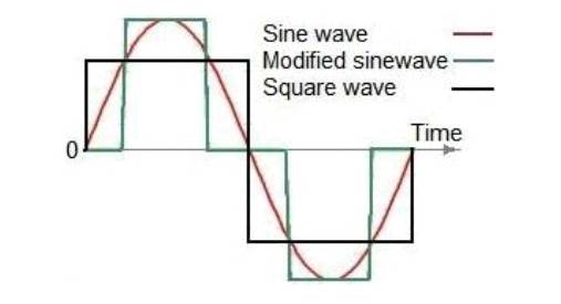
Fig.2.1 Types of inverters waveforms2.3.1.2 Square Wave Inverter
Square wave inverters are largely obsolete, as the waveform shape is not well suited for running most modern appliances. The oscillator as mentioned earlier determines the output wave form. Therefore we would lay emphases on the square wave oscillator. The most common type of square wave inverters is based on astable multi-vibrator.
Limitations of square wave inverters
Despite the square wave being highly economical due its cheapness in terms of cost of production it has limitations such as:
High audio noise which turns to be very visible when it is being used to operate an audio system.
Incompatibility with certain communication gadgets such as fax machine, modems, routers and other equipment which run on motors such as fun, printers, photo copiers etc.
Low surge power
It is to this fact that new system like the modified sine wave which is built on the foundations of modified square wave is being introduced.
2.3.1.3 MODIFIED SQUARE/SINE WAVE INVERTER
An inverter allows the use of 230V electrical appliances from a battery or a solar battery. It must therefore supply a voltage that corresponds to an rms of 230 Volts sine-wave like household main supply or similar. Sine-wave voltages are not easy to generate. The advantage of sine-wave voltages is the soft temporal rise of voltage and the absence of harmonic oscillations, which cause unwanted counter forces on engines, interferences on radio equipment and surge currents on condensers. On the other hand, square wave voltages can be generated very simply by switches, which operated like a door bell were used for this task. They were called chopper cartridge and mastered frequencies up to 200 cycles per second. The efficiency of a modified square wave inverter is higher than the appropriate sine wave inverter, due to its simplicity. With the help of a transformer the generated modified square wave voltage can be transformed to a value of 230 Volts or even higher (radio transmitters).
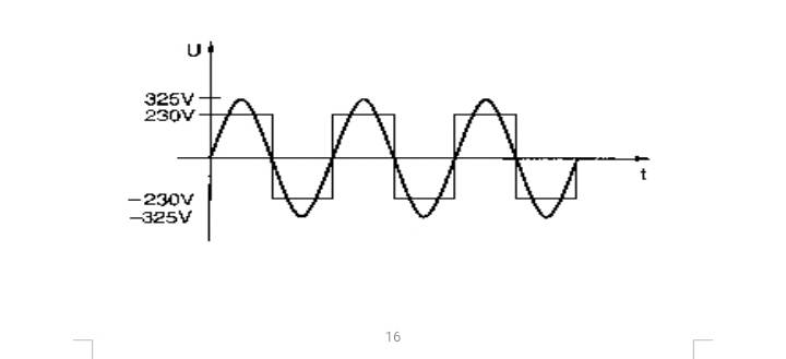
Fig.2.3 Sine-wave voltage square wave voltage with both 230 Volt r.m.s
Fig.2.3 above shows a sine-wave as well as a square wave voltage with in each case an rms of 230 Volts. In both cases an electric lamp would light with the same intensity. This is, as we know, the definition of rms. As we recognize in figure 2.1 however the peak value of the sine-wave voltage is 325 Volts, i.e. factor √2 more than rms. For electrical lamps this is insignificant and electric engines are appropriate for it. Electronic devices were even designed for the peak voltage of sine-wave voltage, because internally they generate DC voltage from the AC supply voltage. A condenser will be loaded on exactly the peak value of the sine-waves. The industry nevertheless manufactured square wave inverters according to this principle in former times.
Our inverter works with a trick, to obtain the same results from square wave voltage as for modified sine-wave voltage.
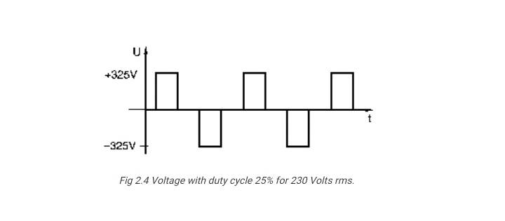
Fig 2.4 Voltage with duty cycle 25% for 230 Volts rms.
Square wave voltage in figure develops the same peak value as sine-wave voltage of 230 Volts, i.e. 230 Volt * √2 = 325 Volts and nevertheless thereby obtains the demanded r.m.s of 230 V. Square wave voltage as shown in the previous figure (full half wave) with peak value of the corresponding sine-wave voltage would cause double amount of electrical power on electric consumers. The trick is, to switch the output power only for one half of every conducting cycle, thus resulting on a duty circle of 25% on behalf of the complete oscillation period. If the calculated double amount of electric power will be generated only half the time effective power remains the same. Industry called this cam shape modified sine, in order to be able to differentiate the devices from conventional square wave inverters.
The inverter may feed nearly all electrical appliances, designed for 230 Volts, with exception of rotary field engines that use condensers for generation of an auxiliary phase (condenser engines).
Engines of this type are used in most refrigerators, washing machines, dishwashers and some few machine tools. Fluorescent lamps with a series inductivity to limit the operating current wont work correctly on our inverter not necessary problem with the output waveform but in terms of power rating and specific function the inverter is designed for. The problem can be solved by increasing the duty cycle on more than 25% while decreasing the peak voltage to 275 Volts. Instead fluorescent lamps with electronics (energy saving lamps) will work very well on the inverter.
2.3.1.4 Modifying Sine Wave Using Discrete Square Waves

Fig. 2.5 Modified Sine WaveReferring to the figure alongside we can see an interesting design of a single modified sine wave cycle made by chopping a few square wave. Here, each positive and negative half cycle contain 3 discrete individual narrow square waves, each block is separated by a notch, the center two pillars are identical but are twice in magnitudes than the extreme ones.
The average value of this special arrangement of discrete square waves effectively imitates a sinusoidal wave. This configuration is as good as a pure sine AC waveform and thus will be suitable to operate almost all appliances safely.
In fact the present design is much more efficient than the usual circuits used in many inverters. From this circuit its possible to get an efficiency of almost 90%, because here the output devices are either turned fully on or fully off.
CHAPTER THREE
3.0 RESEARCH METHODOLOGY
3.1 BRIEF OUTLINE OF THE CHAPTER
This chapter reveals the research design and the different stages of the project are simply revealed. This chapter also reveals the concepts well as techniques adopted in the research about the project. The chapter also explains the various stages in an inverter design.
3.2 RESEARCH DESIGN
A comprehensive comparison of the strengths and weakness existing standard power inverters on the market were made and better system option in terms of the waveform its outputs and the compatibility with various electronic and electrical appliances. The design was centered on the availability and of electrical and electronic components on our local market not disregarding quality.
For smooth construction of this project the system was divided into three sectors namely, AC to DC converter for the charging of the battery, DC to AC inverter for the converting of battery power to (DC) to electricity (AC), and switching system for the co-ordination and synchronization of the system.
3.3 BLOCK BY BLOCK DIAGRAM OF AN INVERTER
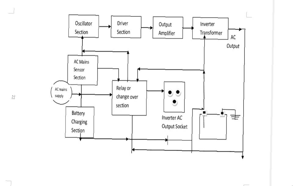
Figs 3.1 Block Diagram of an inverter
The block diagram in the figure above illustrates the principle operation. The power supply fed to the battery for charging section, where it is being regulated for battery changing. Also to the power supply A.C mains sensor which senses the availability of power supply from the Electricity Distribution Company (EDC) of which is fed to the relay or change over section. If EDC power supply is present a signal; goes to the oscillator to block oscillation process, that is, oscillation should not take place and from the relay or change over section power is fed to the output socket for appliances usage. But if EDC is not available, a signal is also sent to start the oscillation process immediately, of which a 50Hz frequency is generated and it is the driver section and output amplifier suited the requirement of the output voltage the inverted transformer takes 12V power supply from the battery and also the amplifier signal from the output amplifier is fed into the inverted transformer and then it is fed into the relay or change over section in which it is further fed to the output socket for appliances usage.
3.3.1 Power Supply
This unit is mainly used to power the whole electronics component in the circuit and it must be a regulated power supply
3.3.2 Battery Charging Section
A battery charge is used to put energy into a cell or battery by forcing an electric current through it. The charging current depends upon technology methods and capacity of the battery being charged. A simple charger work by connection constant D.C power to the battery this is known as the floating charging which is adopted for this project.
3.3.3 The Relay or Change over Section
A relay is an electronic switch that opens and closes under the control of another electrical circuit. In the original form, the switch is operated by an electromagnet to open or close one or many sets of contacts. Normally close contact disconnects the circuit when the relay is activated, the circuit is connected when the relay is inactive and it is called a break contact.
3.3.4 A.C Main Sensor Section
A.C main section which senses the availability of the power supply from which it is fed to the relay.
3.3.5 The Inverter System
The inverter system comprises of four stages; the oscillator stage, amplifier stage, power amplifier stage, power amplifier or driver stage and the transformer stage.
The Oscillator Stage
The oscillator stage is the heart of the device. The inverter needs to generate A.C voltage at a frequency of 50H, hence there has to be some kind of oscillator circuit for this to be achieved. The oscillator stage here is a pulse width modulator IC. The pulse width modulator has an internal RC oscillator, which could be made to oscillate the frequencies in excess of 1MHz, depending on the external component used. The advantage of using pulse width modulator is that the inverter gives low harmonic content of the frequency which is suitable for inductive loads.
The Amplifier Stage
The amplifier stage consist of an electronic amplifier that prepares a small electrical signal for further amplification or processing. Pre-amplifier further amplifies the signal generated from the oscillator before sending it to the driver stage.
Power Amplifier or Driver Stage
The input of the MOSFET has a very high impedance which makes the drive stage dispensable but when MOSFET are connected in parallel, it is often required that their gates be isolated. The driver stage not only matches the oscillator to the amplifier, but it also ensure that the gates of the parallel MOSFETs are properly isolated from each other even if they are driven from the same source.
Transformer Stage
The inverter transformer has two secondary windings. The switching action sends alternating current through the inverter transformer primary winding. This is referred to as push pull action. The core has bipolar utilization. The transformer turns ration can permit higher or lower load voltage. The inverter transformer output is and A.C square wave. Output filter network can be used to obtain sine wave