
A PROJECT REPORT SUBMITTED TO THE DEPARTMENT OF ELECTRICAL ENGINEERING IN PARTIAL FULFILLMENT OF THE REQUIREMENT FOR THE AWARD OF NATIONAL DIPLOMA IN ELECTRICAL ENGINEERING OF THE POLYTECHNIC, IBADAN.
JULY, 2021.
CERTIFICATION
This is to certify that the project work, “CONSTRUCTION OF AN AUTOMATIC CHANGE OVER SWITCH” was done by;
OJO EMMANUEL IBUKUNOLUWA 2018232040045
OKE AYOMIDE DAVID 2018232040046
OKUNADE ADEKUNLE 2018232040047
OLADEJO MAYOWA AYOMIDE 2018232040048
ASOGWA CHUKWUEBUKA PETER 2018232040021
Of the department of Electrical Engineering, The Polytechnic, Ibadan.
_____ _____
M. T. FOLAMI DATE
SUPERVISOR
_____ _____
ENGR. M.O. SADIQ DATE
HOD
DEDICATION
This project work is dedicated to Almighty God for his loving kindness and fulfillment for his grace over us during the study in The Polytechnic, Ibadan. Also to our beloved parents for their encouragement, understanding, love and support during the course of our study.
AKNOWLEDGEMENT
First we express our heartiest thanks and gratefulness to almighty God for his divine blessing makes us possible to complete this project successfully. We feel grateful to and wish our profound indebtedness to our Supervisor ENGR E. T OPALEYE. The deep knowledge & keen interest of our supervisor has worked as an influencer to carry out project. His endless patience, guidance, continual encouragement, constant and energetic supervision, constructive criticism and valuable advice have made it possible to complete this project. We would like to express our heartiest gratitude to him for motivation and valuable suggestions time to time. I am also thankful to other faculty member and the staff of the Electrical department of our institution. We would like to thank our friends & course-mate, who took part in this project and helped us a lot while completing the circuit design work. Lastly, we express our heartily regards to our parents whose blessings have always been with us.
ABSTRACT
LIST OF FIGURE
Fig. 2.2. A Rackmount, adjustable regulated DC power supply 8
Fig. 2.3. Electronic bench power supply unit 9
Fig. 2.4. Alternating current from wall outlet 13
Fig. 2.5. Full wave rectified 13
Fig. 2.6 Full wave rectified +capacitor 14
Fig. 3.1. Pin configuration of 7806 16
Fig. 3.2. Increasing output voltage of regulator 17
Fig. 3.3. Using the capacitor filter and output voltage wave forms are plotted 17
Fig. 3.4. Block diagram of 0-30V variable DC power supply 18
Fig. 3.5. A step-down transformer 18
Fig. 3.6. AC to DC conversion full wave rectification 19
Fig. 3.7. Circuit diagram of smoothening Capacitor 20
Fig. 3.8. Circuit diagram of transient current compensator 21
Fig. 3.9. Circuit diagram of voltage regulator for adjustable 0-30V DC power supply 21
Fig. 3.10. Diagram of variable DC power supply 24
Fig. 4.1. Circuit diagram of variable power supply 26
Fig. 4.2. Diagram of transformer 28
Fig. 4.3. Circuit diagram of a bridge rectifier 29
Fig. 4.4. Diagram of an Electrolytic capacitor 30
Fig. 4.5. Diagram of LM317T 31
Fig. 4.6. Diagram of resistor 33
Fig. 5.1. Soldering wire 36
Fig. 5.2. Flux 36
Fig. 5.3. Wire cutter 36
Fig. 5.4. Multimeter 36
Fig. 5.5. Construction of the 0-30V variable DC power supply with digital display 38
Fig. 5.6. End result of the 0-30V variable DC power supply with digital display 38
LIST OF TABLE
2.1. Categorization of the types of power supplies 14
5.1 Bill of Engineering, Measurement and Evaluation (BEME) 35
TABLE OF CONTENTS
Title Page i
Certification ii
Dedication iii
Acknowledgement iv
Abstract v
List of Figure vi
List of table vii
Table of Contents viii
Chapter One
1.0. Introduction 1
1.1. Background of the Project 2
1.2. Statement of the Problem 2
1.3. Aims of the Project 3
1.4. Contribution to Knowledge 3
1.5. Scope of the Project 3
1.6. Methodology 3
1.7. Definition of Term 4
CHAPTER TWO
2.0 Literature Review 6
2.1. A brief Outline of the Chapter 6
2.2. Historical Background of the Project 6
2.3. Theories and Concept of Research 7
CHAPTER THREE
3.0 Research Methodology 16
3.1. A Brief Outline of the Chapter 16
3.2. Research Design 16
3.3. Block by Block Design of a variable 0-30V DC Power Supply 18
CHAPTER FOUR
4.0. Principles of operation of the project 25
4.1 Brief introduction of the chapter 25
4.2. Principle of operation 26
4.3. Explanation of various unit 27
CHAPTER FIVE
5.0. Construction of the designed project 34
5.1. Brief introduction of the chapter 34
5.2. Choice of materials 34
5.3. Bill of Engineering, Measurement and Estimation (BEME) 35
5.4. Construction of the project 36
5.5. Test(s) results of the test 38
CHAPTER SIX
6.0 Summary, Conclusion and Recommendation 39
6.1. Summary of the project chapter by chapter 39
6.2. Problems encountered 40
6.3. Conclusion 40
6.4. Recommendation 41
REFERENCES 42
CHAPTER ONE
1.1 BACKGROUND OF THE STUDY
The need for constant and stable power supply in a country, state or city cannot be overemphasized. In most developing nations, industries, firms and organizations contest for power supply that is unreliable and insecure, thus marring the effect of productivity and development. In these nations, the quest for secure and reliable power supply remains a dream yet to be achieved. This is as a result of increase in population, industrialization, urbanization (Aguinaga, 2008; Fuller, 2007; Kolo, 2007), and lack of proper planning by the government and utility providers. Most manufacturing industries, firms and institutions such as hospitals and healthcare facilities, financial institutions, data centers and airports to mention, but a few require constant power supply throughout the year. Volatility in power generally delays development in public and private section of any economy (Kolo, 2007; Anon, 2010; Chukwubuikem, 2012). For instance, power failure could lead to prohibitive consequences ranging from loss of huge amounts of money to life casualties (Aguinaga, 2008). This instability in power supply has led to the development of switching systems between national grid power system and standby generators used as backup. In the past decade, various equipment and configurations have been put in place in order to manage this problem (Aguinaga, 2008).
An automatic changeover switching system makes use of contactors, active and passive components and transducers to realize changeover in a shorter time while excluding human interference and its attendant (Chukwubuikem, 2012). The research project is designed for power supply applications. It involves automatic change over between the mains power supply and a standby generating set. The project implements an automatic switching or starting of the power generator, whenever the main power fails. The circuit of the project consists of logical control units, display units, alarm units and relay switches.
The design of the project takes into consideration practical or real life situations and a lot of precautions were put in place to make its performance acceptable, even though it is a prototype design. The basic operation of the project is to switch ON an auxiliary power supply (a generator). This operation connects the power supply from the generator to the load after a predetermined time interval. This is intended to normalize the current from the generator. Switching is possible through the use of the relays. The system was designed to automatically change power supply back to the main supply moments, after the A.C. mains are restored and to switch OFF the generator.
1.2 STATEMENT OF THE PROBLEM
Power failure or outage in a country, state or city is highly detrimental to development in public and private industries. The insecurity associated with constant or frequent power failure or outage brings about limitation to power consistent investments, thus hampering the development of industries and multinational ventures. Processes like carrying out surgical operations in hospitals, laboratories which require constant power supply for research, money transactions between banks and more require constant use of uninterrupted power. In other to solve this problem, an automatic changeover switch was invented. This research covers the design and construction of a single phase digital automatic power changeover. It has the capacity to automatically switch power from national grid to generator and vice versa, once there is power failure in any of the two power supplies and at the same time has the capacity of shutting down a generator set once the mains grid is been restored.
1.3 RESEARCH OBJECTIVES OF THE PROJECT
This project is aimed at constructing a changeover switch which switches ON power from Ibadan Electricity Distribution Company (IBEDC) to a generator when power fails and from generator to IBEDC when power comes back and then shut down the generator automatically.
Therefore, objectives of this study are:
To design a device that will change from public power supply to generator when there is power failure or power outage.
To construct a device that will change from generator to public power supply.
To construct a reliable electrical power device which is highly efficient.
To construct automatic changeover switch.
Studying of various component used in circuit.
1.4 CONTRIBUTION TO KNOWLEDGE
In every home, office or industries, automatic power changeover plays a vital role, that is, It provides a means of switching from utility AC mains to generator in the case of power failure; This project has been improved on the existing types of electromechanical device that has being in use over the years.
1.5 LIMITATION OF THE PROJECT
This work covers only a one phase automatic changeover which can only be used for providing a means of switching from one phase of AC mains to generator set in the case of failure in public utility.
1.6 METHODOLOGY
To achieve the aim and objectives of this work, the following are the steps involved:
Study of the previous work on the project so as to improve it efficiency.
Draw a block diagram.
Test for continuity of components and devices.
Design and calculation for the changeover was carried out
Studying of various component used in circuit.
Construct a digital changeover circuit.
Finally, the whole device was cased and final test was carried out.
- 1.7 DEFINITION OF TERMS
- RELAY: This is an electromagnetic switch. Switching on/off of relays is based on the flow of current through its coil. Relay is used for switching on/off various high voltage circuits. Changeover switch.
- TRANSFORMER: This a device used for stepping up and down of voltages. Transformer is one of the most important components of the automatic changeover switch. The job of the transformer is to step down 220v to15v as the output of the automatic changeover switch.
- RECTIFIERS: The rectifier circuit consists of a rectifies in series with the AC input to rectifies and the load requiring the DC output i.e. it convert AC to DC.
- DIODE: These are two terminal devices which exhibit low resistance to current flow in one direction and hinder resistance to resistance to current in the other direction. Diode is electronic components.
- CAPACITORS: These are passive components that provide a means of storing electrical energy in form of an electric field.
- REGULATOR: These are device that are used control the rate of current or voltage that from in a process.
- LIGHT EMITTING DIODE (LED): This is a small semiconductor devices which emit light when small forward current is applied to them.
- RESISTORS: These are defines as devices that alter or resist the flow of current in an electric circuit.
- POWER OUTAGE/ POWER FAILURE: is the loss of the electrical power network supply to an end user.
- AUTOMATIC CHANGEOVER: is device that automatically transfers power from generator supply to PHCN supply when available and stops the generator without human intervention.
CHAPTER TWO
2.1 BRIEF OUTLINE OF THIS CHAPTER
This chapter presented the existing literature on the study variables of automatic changeover switch. This is secondary data and major sources were textbooks, and previous research reports, publications, journals and Internet etc. It provides a description, summary and evaluation of each source.
2.2 HISTORICAL BACKGROUND OF THE PROJECT
2.2.1 Uninterrupted Continuous Power Supply
Uninterrupted continuous power supply is essential to the industrial sector, university operations, and residential sector. These standby power supply systems are used to supply power to several types of loads such as:
Essential Loads particularly in industrial processes where they require high restarting times or high shut down times. So the automatic transfer from the main supplies to the standby generator must be available.
Critical Loads such as elevators, or lighting in the buildings where the automatic changeover is very important especially in hospitals, malls, and public places.
Sensitive Loads such as computers, equipment and appliances in hospitals, microprocessor, controlled industrial machines, and the monitoring system where it is costly to shut them down and may be required to use of Uninterrupted Power Supply (UPS) system until the automatic changeover happens. If a power failure occurs in any hospital or factory, it is essential to switch between the main supplies and the standby generator and make the transition as smooth and safe as possible (Hatem A., 2014).
A changeover system is an active and pivotal system. When there is a main electrical failure, the changeover system would switch to standby alternative power supply (generator), and return back to the main supply when it is restored. Meanwhile an automatic changeover system allows a smooth and automatic transfer of electrical current between multiple sources of power to loads. The automatic changeover system would ensure that all power sources synchronized before connecting the loads with any source to prevent any feedback current from any source to the load when any one of them takes over.
The changeover would sense the interruption if the main supply remains as unavailable the changeover is sensitive to the fluctuations as voltage drops below a particular level within a specified time in the main power supply line. In this case the automatic changeover would switch on the generator and starts feeding the load through a relay that switches the battery voltage to the ignition of the generator. In a few seconds the generator starts producing full power. During this time, the relays would disconnect the load from the other power supplies simultaneously and connect it to the generator. The changeover senses the main power supply continuously. If it is restored, the changeover would return back the connection between the load and the main supply because of its priority. Then, the generator would shut down after a few seconds. The automatic changeover switch that is being designed would be a complete system with various subsystems and components arranged and linked to function primarily as a means of manipulating the supply of electrical power to any desired load (Hatem A., 2014).
The switching that is obtainable from the ordinary changeover system is usually manual, that is, the user would have to move a lever to change from one source to another. This is usually associated with time wasting as well as some health hazards like electric shock. In order to eliminate this human intervention as well as introduce some speed and precision, there is a need for an automatic changeover switch. The switching system selects the available power source without the intervention of the user; hence, ensuring the availability of supply at all times provided that at least one power source is available. The change from one source to another could only be achieved by device or a system that determines when the change should actually take place and which source is to be given preference to supply the load. Preference would be given to the power sources such that only one source supplies the load at a time and when the (first utilities) source fails, the link immediately connects the (second utilities) source to the load.
When the (second utilities) source fails, the link immediately connects the generator to the load. The paper deals with single-phase power source instead of three-phase source. The three-phase was left for future work. Under/over voltage relays with timers to delay the start-up operation until the power supply is stable were used. A delay associated with the automatic changeover system could reach 5Sec. An uninterruptable Power Supply (UPS) could be used to cover this period. The design problem could be subdivided into basically two parts: the power part and the control power. The power part would supply and handle all the power requirements of the automatic changeover switch. The two input power sources would be handled by this subunit as well as the final output to be supplied to the load. It would also provide the necessary control voltage needed by the control section of the unit as a whole. The control part is actually the brain of the automatic changeover switch. It is the part of the unit that would perform the necessary switching based on the prewired configuration of the relaying and triggering system to be developed. This would ensure that only one source actually supplies the load at all times and the required preference for the power sources would be achieved by this subunit.
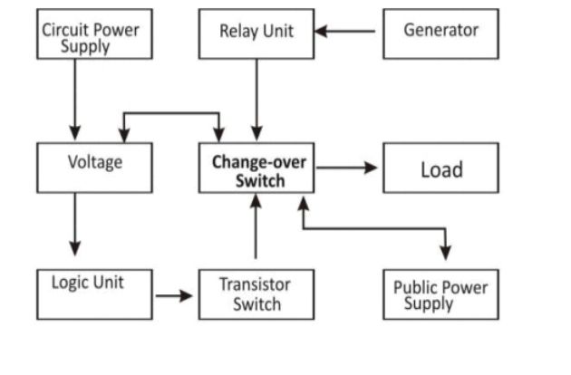
Fig. 2.1 shows the block diagram of a single phase automatic changeover switch.
Fig. 2.1: The block diagram of the system
2.3 THEORIES AND CONCEPT RELATED TO THE RESEARCH
2.3.1 Review of Existing Work
A research by Atser A. et al., (2014), a “3-Phase Automatic Power Change Over switch” has been designed and implemented using three voltage Comparators (LM741 AH1883), 3-input-AND gate (4073), two BC 108 transistors and 12V, 30mA relay as well as some biasing resistors. The voltage Comparators (LM741 AH1883) were biased to sense the unregulated voltage – one for each of the three phases (Rø, Yø, Bø) and then couple the analogue outputs to the 3-input-AND gate (4073). The AND gate produces an output of “0” (OFF) when all the three phase input voltages are all within the normal (preset) range, else it produces an output of “1” (ON) implying a voltage drop or phase failure in at least one of the compared phases. The output of the gate when coupled to the base of switching transistors (BC 108) determines their states (OFF or ON). Since the transistors are configured in a Darlington pair arrangement, the second is ON only when the first is OFF. This then triggers the public power supply ON due to normal phase voltage. On the contrary, when the first transistor is ON, the 12V battery produces a potential which triggers ON the alternative power source (Generator) via the 12V, 30mA relays hence breaking contact from the public power supply to the Generator side. The switch is tested to have function optimally within ±5% nominal voltage of 220 or 415V supply at the point of changing over to an alternative power source. Hence this device can be of Industrial or domestic use where 3-phase power supply is available with a stand-by power source.
Power supply instability in developing countries creates a need for automation of electrical power generation or alternative sources of power to back up the utility supply. This automation becomes necessary as the rate of power outage becomes predominantly high. Most industries and commercial processes are partly dependent on generators and public power suppOkayly which is epileptic especially in tropical African countries where Nigeria forms a part. Therefore, if the processes of power change-over between these two power-supplying sources are manual, human error during change-over connections may occur; leading to machine damage, electric shock/electrocution as well as increased down time consequently introducing massive losses (Mazur and Rocks, 2001).
To ensure the continuity of power supply, many commercial/industrial facilities depend on both utility service and on-site generation (generator set). And because of the growing complexity of electrical systems it becomes imperative to give attention to power supply reliability and stability. Over the years many approaches have been implored in configuring a changeover system. Some of them are discussed below.
2.3.2 Manual Changeover Switch Box
Manual changeover switch box separates the source between a generator and public supply. Whenever there is power failure, changeover is done manually by human and the same happens when the public power is restored and this is usually accompanied with loud noise and electrical sparks.
2.3.3 Limitations of Manual Changeover Switch Box
Below are some of the limitations of manual changeover switch box.
- Time wasting whenever there is power failure
- It is strenuous to operate
- It is causes device, process or product damage
- It could cause fire outbreak
- It makes a lot of noise.
- Maintenance is more frequent as the changeover action causes wears and tears.
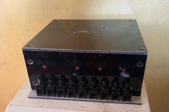
Figure 2.2 is a diagram of manual changeover switch box
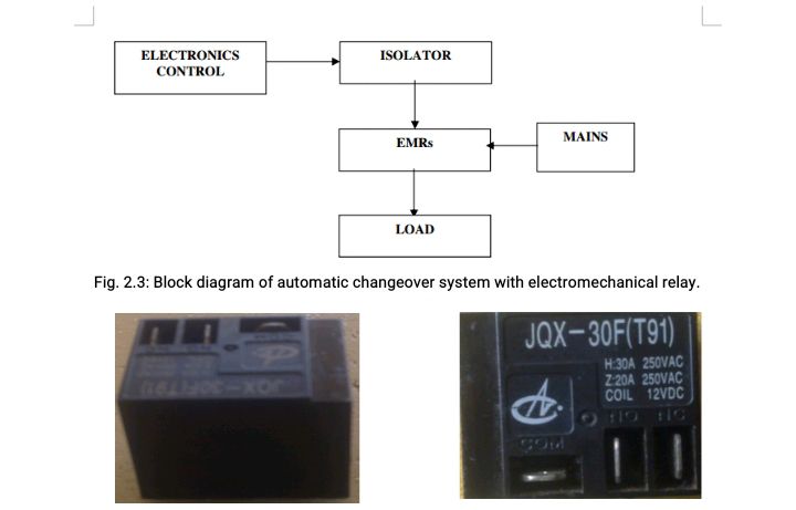
Fig.2.2: Manual changeover switch box
2.3.4 Automatic Changeover System with Electromechanical Relays (EMRs)
A relay is an electromagnetic device that is activated by varying its input in order to get a desired output. Recently, electromechanical relays (EMRs) have been used with other component to implement automatic changeover. Such components could be logic gates, transistors, opto-coupler, microcontroller etc. Most of these components make use of 5v since they are Transistor Transistor Logic (TTL) based. Such control system must be properly isolated from the relay as shown in figure 2.3 to avoid the flow back of ac signal into the control electronics.
Fig. 2.3: Block diagram of automatic changeover system with electromechanical relay.
Figure 2.4: Diagram of electromechanical relays.
This type of changeover system is better than the manual changeover with switch box because it is automatic and faster, but has its limitations which are listed below:
• Noise associated with switching of relays.
• Wear and tear.
• Arching which could cause fire outbreak.
• High Component count making the system more prone to failures.
2.3.5 Changeover with Automatic Transfer Switch
This type of changeover system has an automatic transfer switch which monitors the alternating current (AC) voltage coming from the utility company line for power failure conditions. Upon detection of power failure for predetermined period of time, the standby generator is activated (started), after which the load is transferred from utility to the standby generator. Then, on return of the utility feed, the load is switched back after some time and the generator is stopped. The limitations of this approach are more or less the same thing with automatic changeover system with electromechanical relays.
2.3.6 Description of the New System
In view of the limitations of the above previous works, this paper proposes and implements a changeover system that drastically reduced the shortcomings. The noise, arching, wear and tear associated with EMRs are eliminated totally by the introduction of solid state relay. Digital components were also used to make the work more reliable unlike the previously existing ones that make use of circuit breakers. Also an AT89C52 microcontroller was also incorporated to help improve the speed of automation. The system is controlled by a software program embedded in the microcontroller. This work is handy and portable compared to the bulky works done previously. It also have some important features like liquid crystal
display (LCD) which makes the system user friendly, an alarm system for indicating generator failure, automatic phase selector for selecting most appropriate phase, over-voltage and under-voltage level monitoring. Economically, this project is of low cost due to the use of ICs in place of discrete components.
2.3.7 Description of Solid State Relays
With emergence of semiconductor technology the production of solid state relays were made possible which in many applications out perform their predecessors. A typical solid state relay consists of a light emitting diode (LED) optically coupled to a photovoltaic device such as a Field Effect Transistor (FET). Light from the LED creates a voltage across the photovoltaic array and activates the output FET. FET is the preferred switching element in a solid state relay because it presents comparatively less electric resistant when it is in a conductive state than a triac in the same state and therefore generates less heat. As a result of this, FET requires smaller heat dissipating fins and could reduce the overall size of the solid state relay. The internal circuitry of a typical solid state relay is shown figure 2.5 while figure 2.6 is a solid state relay from FOTEK:
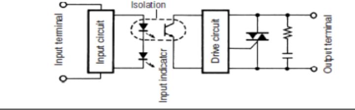
Fig. 2.5: The internal circuitry of a typical solid state relay
Fig. 2.6: Solid state relay from FOTEK
2.3.8 Advantages of solid state relay over electromechanical relay
Solid state relay has the following properties which gave it an edge over the EMR:
It has no moving coil part.
It has long operating life.
Bounce-free operation.
It has immunity to electromagnetic interference.
It has high switching speed
It could be controlled by a low signal (3v).
Multi function integration
No arching or sparking.
No acoustical noise.
High reliability.
Resistance to shock and vibration.
Wide input voltage range.
High input-output isolation.
Because of the low signal control feature, solid state relays could be driven directly by the microcontroller the use of interface drivers. This could save space, time and money, reduce component count as well as improve product life, performance and reliability.
2.4 THE STAND-BY POWER UNIT (GENERATOR)
The stand-by generator set is commonly used to supply emergency power to most of the power consumers where the mains supply is unstable. For best performance of the system, we must put into consideration the type of generator, engine type, its cooling system and fuel, the load capacity and the operating environment. Whatever cooling system is used to cool the generator, it is recommended that the heated air be channeled outside through an exhaust pipe while provision should be made to bring in fresh air so that the generating room, where the generator is installed, can be kept from becoming excessively hot, as this might cause damage to the engine of the generating set (Ezema, et al., 2012).
Furthermore, the lubrication of the set is much important; the recommended lubricant should be used in order to maintain smooth and prolonged life span of the set by reducing wear and tear of the engine and other parts due to friction (Ezema, et al., 2012). Finally, it is important to determine the correct rating of the mechanical engine to drive a given generator so that it has the minimum capacity necessary to supply the selected load.
2.5 FEATURES OF GENERATOR TO BE USED ON AUTOMATIC CHANGE OVER SWITCH
The automatic change-over switch can be used in any place where alternative power is needed to complement the main power supply. In this project, a generating set is used as an alternative power supply. Thus, it is very important to note the necessary peripherals to be used with the automatic change-over switch.
(a) The generator must have electrical ‘start and stop’ facility.
(b) The generator’s battery has to be in good condition always.
(c) The inter-connecting cables must be in good order (Ezema, et al., 2012).
CHAPTER THREE
3.0 RESEARCH METHODOLOGY
3.1 A BRIEF OUTLINE OF THE CHAPTER
The methodology of this research involves construction of an Automatic Changeover Switch. The incorporation of the Automatic Changeover Switch involves the use of automatic switching between the phases of the mains supply and automatic switching between the generator/backup power supply. The main objective of this research is to compare the stress levels experienced during automatic switching with the aid of the Automatic Changeover Switch and the stress levels experienced when the switching is done manually, analyzing the relationship between them and drawing conclusions based on the analysis. Also the time delay during switching with the use of the Automatic Changeover Switch and with the switching done manually are also compared and analyzed and conclusions are drawn from the analysis.
3.2 RESEARCH DESIGN
3.2.1 Design Consideration of a Change-over Switch
In designing and construction of this change-over switch, a generator with the capacity of 12KVA was used and its rating determines the ratings of the components and circuit elements to be used. It does not function with a faulty generating set and the generator must have a manual starter and engine stopper which is a sine quo non to the function of the automatic change-over. This automatic change-over switch is designed and constructed with the aim of achieving the following automatic actions.
To automatically switch on the generator and switch over the load to the generator whenever there is mains power failure.
To automatically switch over to mains supply once restored and simultaneously switch off the generator.
However, a good switch should be the one whose contact is made in such away as to limit the arc formation by having no contact-bounce and by having contacts made of good conductive, corrosion resistance and wears resistance materials. Change-over switch must have adequate insulation and must be so contracted and located as not to constitute a potential hazard. A good change-over switch should also have tight contact points so as to limit or eliminate the possibility of partial contact at the contact point. The partial contact may lead to fire outbreak or possible damage to the contactor itself.
The following are the advantages that are associated to the change-over switch.
- It minimizes damages to lives and equipment since it has its own monitoring system and its switching requires no human contact with the switch, thus eliminating human error.
- It reduces change- over time to a minimum, due to its fast response to power restoration.
- It maintains high quality of service through its fast and prompt response.
- Moreover, the unit is portable, easy, convenient and safe to install.
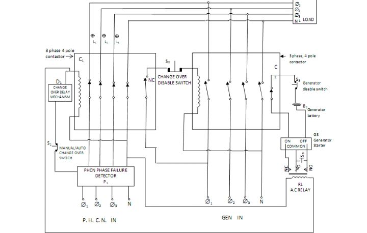
Fig. 3.1: Phase Automatic Change Over with Generator Control
3.3 MATERIALS AND COMPONENTS
3.3.1 Materials
Three voltage Comparators (LM741 AH1883), 3-input-AND gate (4073), two BC 108 transistors, two 12V; 30mA relays, biasing resistors, 240/12V; 500mA transformer, bridge rectifier (1N4002), two voltage regulators (LM7812 and LM7805), variac, Multimeter plus some other components.
3.3.2 Components
The components involved in the construction of the ATS are made up mainly of contactors and relays. This is so because they are very effective when used for electrical controls. They operate on the principle of electromagnetism and can carry out automatic switching very effectively. They are very rugged and durable and their operation is similar but the difference between them is that contactors can switch higher currents. Other components include miniature circuit breakers and indicator lights. On table 3.1 is a list of components to be used and their ratings.
Table 3.1 List of components and rating
Quantity
Component
Rating
2
Magnetic contactor
220/240, 20A
1
Solid state relay
12V
1
Relay (ac)
220/240V
2
Miniature circuit breaker
220/240V, 20A
3
Indicator light
220/240V
2
Digital voltmeter
220V
1
Emergency switch
NC/NO contact
3.4 DESCRIPTION OF COMPONENTS
3.4.1 Relay
A relay is usually an electromechanical device that is actuated by an electrical current. The current flowing in one circuit causes the opening or closing of another circuit. Relays are like remote control switches and are used in many applications because of their relative simplicity, long life, and proven high reliability. Relays are used in a wide variety of applications throughout industry, such as in telephone exchanges, automatic changeover switch, digital computers and automation systems. Highly sophisticated relays are utilized to protect electric power systems against trouble and power blackouts as well as to regulate and control the generation and distribution of power. In the home, relays are used in refrigerators, washing machines and dishwashers, and heating and air-conditioning controls. Although relays are generally associated with electrical circuitry, there are many other types, such as pneumatic and hydraulic. Input may be electrical and output directly mechanical, or vice versa.
3.4.2 Basic Operation of Relay
All relays contain a sensing unit, the electric coil, which is powered by AC or DC current. When the applied current or voltage exceeds a threshold value, the coil activates the armature, which operates either to close the open contacts or to open the closed contacts. When a power is supplied to the coil, it generates a magnetic force that actuates the switch mechanism. The magnetic force is, in effect, relaying the action from one circuit to another. The first circuit is called the control circuit; the second is called the load circuit.
There are three basic functions of a relay:
On/Off Control,
Limit Control and
Logic Operation.
On/Off Control: Example: Air conditioning control, used to limit and control a “high power”
load, such as a compressor
Limit Control: Example: Motor Speed Control, used to disconnect a motor if it runs slower or faster than the desired speed
Logic Operation: Example: Test Equipment, used to connect the instrument to a number of testing points on the device under test.
3.4.3 Types of Relays
There are two basic classifications of relays: Electromechanical and Solid State. Electromechanical relays have moving parts, whereas solid state relays have no moving parts. Advantages of Electromechanical relays include lower cost, no heat sink is required, multiple poles are available, and they could switch AC or DC with equal ease.
i. Electromechanical Relays
General Purpose Relay: The general-purpose relay is rated by the amount of current its switch contacts could handle. Most versions of the general-purpose relay have one to eight poles and could be single or double throw. These are found in computers, copy machines, and other consumer electronic equipment and appliances.
Power Relay: The power relay is capable of handling larger power loads – 10-50 amperes or more. They are usually single-pole or double-pole units.
ii. Solid State Relays
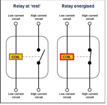
These active semiconductor devices use light instead of magnetism to actuate a switch. The light comes from an LED, or light emitting diode. When control power is applied to the device’s output, the light General Purpose Relay is turned on and shines across an open space. On the load side of this space, a part of the device senses the presence of the light, and triggers a solid state switch that either opens or closes the circuit under control. Often, solid state relays are used where the circuit under control must be protected from the introduction of electrical noises. Advantages of Solid State Relays include low EMI/RFI, long life, no moving parts, no contact bounce, and fast response. The drawback to using a solid state relay is that it could only accomplish single pole switching (Hatem 2014). Figure 3.2 is a relay switch at rest and when is energize.
Fig. 3.2: Diagram of a Relay switch
3.3.5 Operating Principle of Contactors
Unlike general-purpose relays, contactors are designed to be directly connected to high-current load devices. Relays tend to be of lower capacity and are usually designed for both normally closed and normally open applications. Devices switching more than 15 amperes or in circuits rated more than a few kilowatts are usually called contactors. Apart from optional auxiliary low current contacts, contactors are almost exclusively fitted with normally open (“form A”) contacts. Unlike relays, contactors are designed with features to control and suppress the arc produced when interrupting heavy motor currents. When current passes through the electromagnet, a magnetic field is produced, which attracts the moving core of the contactor. The electromagnet coil draws more current initially, until its inductance increases when the metal core enters the coil. The moving contact is propelled by the moving core; the force developed by the electromagnet holds the moving and fixed contacts together. When the contactor coil is de-energized, gravity or a spring returns the electromagnet core to its initial position and opens the contacts.
For contactors energized with alternating current, a small part of the core is surrounded with a shading coil, which slightly delays the magnetic flux in the core. The effect is to average out the alternating pull of the magnetic field and so prevent the core from buzzing at twice line frequency. Because arcing and consequent damage occurs just as the contacts are opening or closing, contactors are designed to open and close very rapidly; there is often an internal tipping point mechanism to ensure rapid action. Rapid closing could, however, lead to increase contact bounce which causes additional unwanted open-close cycles. One solution is to have bifurcated contacts to minimize contact bounce; two contacts designed to close simultaneously, but bounce at different times so the circuit would not be briefly disconnected and cause an arc.
A slight variant has multiple contacts designed to engage in rapid succession. The first to make contact and last to break would experience the greatest contact wear and would form a high-resistance connection that would cause excessive heating inside the contactor. However, in doing so, it would protect the primary contact from arcing, so a low contact resistance would be established a millisecond later. Another technique for improving the life of contactors is contact wipe; the contacts move past each other after initial contact on order to wipe off any contamination. (Lanre O.R. 2014). Figure 3.3 is a diagram of contactor switch
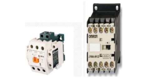
Fig. 3.3: Diagram of a Contactor switch
3.4 DIGITAL MULTIMETER
The digital multimeter, DMM, is one of the most common items of test equipment used in the electronics industry today. While there are many other items of test equipment that are available, the multimeter is able to provide excellent readings of the basic measurements of amps, volts and ohms. In addition to this the fact that these digital multimeters use digital and logic technology, means that the use of integrated circuits rather than analogue techniques, enables many new test features to be embedded in the design. As a result, most of today’s digital multimeters incorporate many additional measurements that could be made.
3.5 DMM FACILITIES
While the facilities that a digital multimeter could offer are much greater than their analogue predecessors, the cost of DMMs is relatively low. DMMs are able to offer as standard the basic measurements that would typically include:
Current (DC)
Current (AC)
Voltage (DC)
Voltage (AC)
Resistance
However, using integrated circuit technology, most DMMs are able to offer additional test capabilities. These may include some of the following:
Capacitance
Temperature
Frequency
Transistor test – hfe, etc
Continuity (buzzer)
While some of these additional test features may not be as accurate as those supplied by dedicated test instruments, they are nevertheless very useful, especially where approximate readings only are needed.
In addition to an increase in the number of basic measurements that could be made, refinements of some of the basic measurements are also available on some models. True RMS multimeters are available. In many instances, AC waveforms use forms of average measurements that are then converted to RMS measurements using a form factor. This method of measurement is very dependent upon the shape of the waveform and as a result a true RMS digital multimeter may be required. In addition to the availability of a true RMS meters, similar refinements of the other basic measurements are also available in some instances.
In addition to the additional measurement capabilities, DMMs also offer flexibility in the way measurements are made. Again this is achieved because of the additional capabilities provided by the digital electronics circuitry contained within the digital multimeter. Many instruments would offer two additional capabilities:
Auto-range: This facility enables the correct range of the digital multimeter to be selected so that the most significant digits are shown, i.e. a four-digit DMM would automatically select an appropriate range to display 1.234 mV instead of 0.012 V. Additionally it also prevent overloading, by ensuring that a volts range is selected instead of a millivolts range. Digital multimeters that incorporate an auto-range facility usually include a facility to ‘freeze’ the meter to a particular range. This prevents a measurement that might be on the border between two ranges causing the meter to frequently change its range which could be very distracting.
Auto-polarity: This is a very convenient facility that comes into action for direct current and voltage readings. It shows if the voltage of current being measured is positive (i.e. it is in the same sense as the meter connections) or negative (i.e. opposite polarity to meter connections). Analogue meters did not have this facility and the meter would deflect backwards and the meter leads would have to be reversed to correctly take the reading. Figure 3.3 is a diagram of digital multimeter and table 3.2 is the rough estimate of cost implication of the project.
Fig. 3.4: Diagram of Digital multimeter
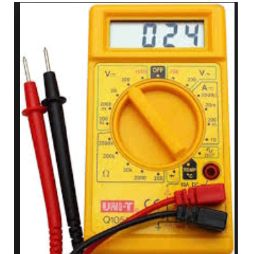
Table 3.2: Rough Estimate of the Cost Implication of the Project
Quantity
Component/Materials
Unit
Total Cost(N)
2
Magnetic Contactor, 220/240V, 20A
2,500
5,000
2
Relay, 220/240V
1,500
3,000
2
Digital voltmeter,220/240
1,200
1,200
2
Miniature circuit breaker, 220/240V, 16A
1,500
1,500
2
Indicator Light, 220/240V
300
600
1
Package box
2,500
2,500
2m
Mounting rail
300
600
15m
Single core cable, 2.5mm2 (red)
50
750
15m
Single core cable, 2.5mm2 (black
50
750
15m
Single core flexible cable, 0.75mm2
30
450
1
Packet screw
300
300
1
Packet Nylon cable ties
300
300
OVERALL TOTAL……………………………………….. N16,950
CHAPTER FOUR
4.0 PRINCIPLES OF OPERATION OF THE PROJECT
4.1 Brief Introduction of the Chapter
This chapter reveals the research design, and the different stages of the project, the concept as well as the techniques adopted in the project and the working principle of the project.
4.2 Principle of Operation
4.2.1 Working Operation of A 10 KVA Change Over Switch
The project is designed such that everything takes place automatically and the appliances are never switched OFF, just reverted from inverter AC to Mains AC and vice versa during mains power failures and restorations.
A scenario in which the change over switches from a generator source to AC mains whenever is available, but not design to put on the generator when there is AC mains power out. All these are done automatically.
Fig. 4.1: Circuit diagram of construction of Automatic Changeover Switch
The entire unit requires three relays; the relays are serving as switches, the first relay is used to switch between the outputs of both the main and generator, that is, LIVE and neutral from their respective direct connections before entering the house.
The second relay is used such that when there is the relay NORMALLY CLOSED (NC) remains closed and the house is supplied with the available voltage source.
When the generator is ON as a result of outage, the NORMALLY OPEN (NO) overrides on the NC of the initial condition, while the NC remains closed, the house is supplied with the generator voltage.
The third relay is a small 12V relay that is used to permanently put off the generator when there is power supply. The relay works by first an LED which comes on to show that there is power supply available and shut down the generator.
The microcontroller used for this project is ATMEGA 8 forms the heart and central controlling unit for the project as it controls the three relays used for the switching of the whole processes. From the control of the first relay to the last relay, it is being governed by microcontroller. The entire unit is microcontroller based, the microcontroller through the communication received from the first relay which serves as a monitoring and switching device, the first relay monitor either the IBEDC or generator’s voltage to know which to switch to by comparing the voltages which is displayed on the LED ( Light emitting diode ) display. If the voltage compared is IBEDC it relates this to the microcontroller which triggers the second relay to put off the existing source, that is, generator, and switch the supply back to IBEDC and the microcontroller triggers the third relay which put ON an LED to show power supply availability and to put off the generator
When there is power outage, which the microcontroller senses through the second relay by the compared voltages value, the microcontroller triggers this relay to switch to existing generator. The rating of the first relay is a 12V 80A, the second relay is 12V 30A while the third relay is 12V 25A. Other components used are sub-circuit needed for the working of the major components explained above.
A sub-circuit called reset circuit is connected to the microcontroller to enable its operation, the heart of the project is the control unit which uses an ATMEGA8 microcontroller, this microcontroller controls the activities of all major components connected to it.
Fig. 4.2: Circuit Diagram Showing the Microcontroller Section Connection to the Reset
This section gives instruction to the all the sub-circuits connected to it while all the sensors monitoring the environmental parameters report to the microcontroller via a written set of programming codes written in ASSEMBLY language to activate it sensing operation, measure and give the value in analogue data to the microcontroller which converts it to digital signal, a format recognized by the ATMEGA Circuit. It constantly monitors the signal from the relays before it takes action. It checks if any corrective action is to be taken for the condition at that instant of time. In case such a situation arises, it activates the actuators to perform a controlled operation.
A programmer is used to program these instructions into the microcontroller chip. The assembler software; MPASM converts text to machine code. Inside the microcontroller, the program is stored in the EPROM (Electrical Programmable Read Only Memory). The instructions programmed into the microcontroller work by moving and manipulating data in memory locations as user files and registers call RAM (Random Access Memory).
Master clear reset circuit
From the diagram shown in the above figure, Pin 1 is the reset pin. The reset logic is used to place the device into a known state. The source of the reset can be determined by using the device status bits. The reset logic is designed with features that reduce system cost and increase system reliability. While MCLR voltage is less than +4V, the microcontroller is held at reset point, when the voltage rises beyond +4V, program begins. Diode IN4148 D4 helps discharge the capacitor quickly when power is down; Resistor R33 is chosen as 10KΩ to limits the current flowing into MCLR from capacitor C3 in the event of MCLR pin breakdown.
It should be noted that most of the microcontroller pins are input pins by default apart from some designated pins like RESET, OSILLATORS, +VE and –VE pins, therefore to set some pins to output pins in order for signals to be generated from them, the following commands/ instruction were initiated at the start of the codes writing before proceeding to others set of instructions. We can configure the ports as output; this is done through program codes written thus;
BCF STATUS, PC0: PC5; (BIT CLEAR PORT C);
To set as output Clear PORTC
In the above piece of codes, the first line selects the bank where the register PORTC is found, that is Bank0. Clearing the port, done with line two, initializes the port. The third line is responsible for moving to Bank1 where the TRIS register is found, clearing TRIS means all the pins of port are outputs (the direction of data is to the LCD), and finally the last line moves back to the default Bank0. Bits 5 and 6 of the status register are responsible for the bank selection.
Another sub-circuit know as relay driver From the above circuit, each relay section was used to switch the Feeder ON and OFF, with the target condition in mind, the generate +12V supply from the power supply section which is applied to the coils of the each relay, capacitor 470uF was connected to prevent spikes by eliminating over and false clicking of the relay; diode IN4007 connected together with relay and connected in a reversed direction to function as a protection diode, transistor TIP 41 was used to amplify the voltage to the microcontroller and the resistors 200 and 10K resistors are protecting the microcontroller pin against over voltage.
4.3 EXPLANATION OF VARIOUS UNITS
i. RELAY: This is an electromagnetic switch. Switching on/off of relays is based on the flow of current through its coil. Relay is used for switching on/off various high voltage circuits changeover switch.
ii. TRANSFORMER: This a device used for stepping up and down of voltages. Transformer is one of the most important components of the automatic changeover switch. The job of the transformer is to step down 220v to15v as the output of the automatic changeover switch.
iii. RECTIFIERS: The rectifier circuit consists of a rectifies in series with the AC input to rectifies and the load requiring the DC output i.e. it convert AC to DC.
iv. DIODE: These are two terminal devices which exhibit low resistance to current flow in one direction and hinder resistance to resistance to current in the other direction. Diode is electronic components.
v. CAPACITORS: These are passive components that provide a means of storing electrical energy in form of an electric field.
vi. REGULATOR: These are device that are used control the rate of current or voltage that from in a process.
vii. LIGHT EMITTING DIODE (LED): This is a small semiconductor devices which emit light when small forward current is applied to them.
RESISTORS: These are defines as devices that alter or resist the flow of current in an electric circuit.
TRANSISTORS: These are three terminal devices which is used in automatic changeover switch circuit to generate oscillation signal, amplification of signal and switch on/off various circuit.
CONTACTOR: This is an electrically controlled switch used for switching a power circuit, similar to a relay except with higher current ratings. A contactors controlled by a circuit which has a much lower power level than the switched circuit.
CONNECTOR: This is an electrical device that is used for joining circuit together.
FUSE AND FUSE HOLDER: This is a very important component in an automatic changeover switch. Fuses are used to self-destruct and protect the circuit from flow of heavy voltage.
CUT OUT FUSE: This is a combination of a fuse and switch, used in primary- overhead feeder lines and taps to protect.
VERO BOARD: This is a brand of strip board, a pre-formed circuit board material of copper strips on an insulating board.
SOLDER: This is a fusible metal alloy used to join together metal work pieces and having a melting point below that of the work piece.
JUMPER: This a short length of conductor used to close a break in or by pass of an electrical circuit.
CHAPTER FIVE
5.0 CONSTRUCTION OF THE DESIGNED PROJECT
5.1 Brief Introduction of the Chapter
This chapter reviews the materials used in the construction of project. It contains the choice of materials used; the Bill of Engineering Measurement and Evaluation (BEME), construction of the project and the test result.
5.2 Choice of Materials
The following factors are considered for choosing the materials:
Magnetic Contactor, 220/240V, 20A
Relay, 220/240V
Digital voltmeter, 220/240
Miniature circuit breaker, 220/240V, 16A
Indicator Light, 220/240V
Package box
Mounting rail
Single core cable, 2.5mm2 (red)
Single core cable, 2.5mm2 (black)
Single core flexible cable, 0.75mm2
Packet screw
Packet Nylon cable ties
5.2.1 Materials used
Magnetic Contactor
Relay
Digital voltmeter
Miniature circuit breaker
Indicator Light
Package box
Mounting rail
Single core cable
Single core flexible cable
Packet screw
Packet Nylon cable ties
5.3 BILL OF ENGINEERING MEASUREMENT AND EVALUATION (BEME) TABLE
5.3.1 Bill of Engineering Measurement and Evaluation (BEME) for a 10KVA Automatic Change Over Project
S/N
Components
Units
Qty
Total (N)
1
CAPACITORS: 10µF, 1000µF, 47 µF
FARADS
3
700
2
DIODES: IN4007, IN4148
22
900
3
RESISTORS:47(, 330 (, IK(, 10K(, 220(, 10(, 22K(, 100(, 150K(
OHMS
(()
1
1500
4
LED DISPLAY
2
800
5
ATMEGA 8
3500
6
12V 30A, 12V 80A AND 12V 25A RELAYS
6500
7
TRANSISTOR BC548
6
850
8
TRANSISTOR BC557
4
680
9
PRINTED CIRCUIT BOARD PCB PANEL
3700
10
ETCHING CHEMICAL
1500
11
1mm DRILL BIT
1DOZEN
1200
12
PLASTIC CASING (ACCOBOARD)
1X2
4500
13
IC SOCKETS 4 X4
2
600
14
IC SOCKETS 8X8
1
840
15
IC SOCKETS 14X14
960
16
CABLES
2000
17
SOLDERING LEAD
1
6500
18
BOLTS AND NUTS, BLACK SCREWS
5DOZENS
19
CONNECTORS
3000
TOTAL
N39,740
5.4 Construction of the Project
5.4.1 Design
As stated earlier in previous sections, this ATS design is for single phase supply. The circuit can be divided into two major parts namely
The Power circuit
The Control circuit
Though these two circuits work hand in hand, the control circuit is the brain box of the device that ‘gives the orders’. The design is an adaptation from some already existing designs but some modifications have been carried out on it to ensure that it takes care of some issues not considered in previous designs. The circuit for this project work is therefore designed to perform the following functions.
Ensure that both sources of power do not supply at the same time and this is ensured through its electrical interlocks.
It ensures that when primary supply is restored, it is monitored and confirmed that it is not just momentary or a surge before it stops the generator and connects it to load.
Ensures that the whole installation i.e. the device and the load is well protected with the use of miniature circuit breakers
5.4.2 Construction
- The Power section: The power section of the ATS is responsible for the switching between generator and primary source of supply. The circuit diagram for this is shown in figure 5.1
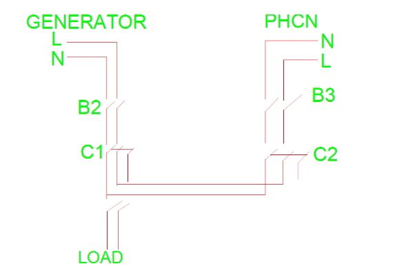
Fig. 5.1: Power Circuit
The miniature circuit breakers, B2, and B3 are meant for isolation and protection of various parts of the circuit. The contactors C1 and C2 are the generator and primary source contactors respectively. The control circuit send signals to this circuit on when to switch and to which supply to switch.
- The Control section: This is the brain box of the device. It controls everything that goes on in the entire ATS and ensures that the circuit works exactly the way it is configured. This section can be divided into two parts which are the auto – start section and the auto – transfer section. The auto – transfer section can be further divided into two circuits namely the generator auto – transfer circuit and the primary source auto – transfer circuit.
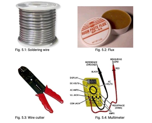
5.4.2 Various Tools & Equipment Needed For Fabrication
Fig. 5.1: Soldering wire Fig. 5.2: Flux
Fig. 5.3: Wire cutter Fig. 5.4: Multimeter
5.4.3 Soldering
Soldering is a process in which two or more metal items are joined together by melting and flowing a filler metal into the joint, the filler metal into the joint, the filler metal having a relative low melting point. Soft soldering is characterized by the melting point of the filler metal, which is below 40000C (7520F). The filler metal used in the process is called solder.
In a soldering process, heat is applied to the parts to be joint by capillary action and to bond to the materials to be joined by wetting action. After the metal cools, the resulting joints are not as strong as the base metal, but have adequate strength.
Soldiering is something that needs to be practiced. These tips should help you began successful so you can stop practicing and get down to some serious building.
Keep the iron tip clean. A clean iron tip means better heat conduction and a better joint. Use a wet sponge to clean the tip between joints.
Double check points. It is good idea to check all the solders joints with an Ohm meter after they are cooled. If the joint measures any more than a few tenths of an ohm, then it may be a good idea to resolder it.
Use the proper iron. Remember that bigger joints will take longer to heat up with an 30W iron than with a 150w Iron.
Solder small parts first. Solder resistors, jumper leads, diodes and any other small parts before you solder larger parts like capacitors and transistors. This makes assembly much easier.
5.5 Test(s) Results of Test
The importance of testing in the field of Electronic and Electrical Engineering before, during and after the implementation of a design cannot be overemphasized. This is of great importance because there is need to analyze the functions and working conditions of components before using them in a circuit. Various tools and equipment are available for carrying out these tests depending on the kind of test. Circuits could also be simulated using different software packages in order to observe how they work and make necessary corrections and adjustments before implementation on hardware.
In the course of implementing these circuits, the test instruments used were the multimeter, variable and fixed dc supply, variable and fixed ac supply. The 230Vac relays were tested to ascertain their working condition; each of them was tested separately. The relay was plugged to the base and a fixed 230V a.c source was used in energizing it through pins A1 and A2 (the coil) and it was confirmed working. The contacts Normally Open (N.O) and Normally Close (N.C) were also tested using a multimeter in the continuity range. The N.C contacts were short circuited when the relay was not connected to supply (i.e. when the relay was not energized) and open circuited when the relay was energized. Reverse was however the case for the N.O contacts as they were open circuited when the relay was de-energized and short circuited when it was energized.
5.5.1 Circuit Testing and Results
The test on the contactor was carried out using the supply from the generator and a 60W bulb which served as the load. The supply was connected to the contactor via the terminals A1 and A2 (coil), a neutral and live supply to three of its incomer terminals as the contactor is four pole and the 60W bulb connected to the three corresponding outgoing terminals. The voltage was varied from 0V and the contactor did not respond until 110V. At 110V, the contactor responded by energizing and the bulb came on but the intensity was low. As the voltage was increased, the intensity of the lamp also increased. This implies that the contactor will be suitable for proper operation between 110- 230Vac supply. Likewise the voltmeter was tested by connecting three-single phase supply to its pins. The circuit breakers and indicator lamps were also tested and confirmed working.
The finished work was tested with a 2.0kVA Generator with a rated capacity of 8.33A as the secondary source and a mini residential apartment with a connected load of about 14A supplied from the primary source. For the generator to work perfectly with the circuit for automatic starting and transfer, the key must be at the “ON” position. The terminal of the kick starter has six wires connected to it, two of which are for switching off the generator, two for putting it ON and the other two for starting it. In connecting the automatic power transfer switch to the generator, only four of the wires which are used for starting and switching off the generator are needed.
In order to detect the function of each wire, a short test was conducted. A short piece of wire peeled on both ends was taken to be the bridging plug. To find out the wires meant for starting the generator, the key was turned to the ON position and two of the six wires were picked simultaneously at random and bridged with the short piece of wire. When a particular two were bridged, the generator cranked and was about to start indicating the starting wires of the gen. It should be noted however that the generator can either be started by pulling it or with the key. It can only be started with the key or work with the project if the battery is fully charged and in proper working condition. If the battery is bad, the generator will not work with the ATS and cannot also be started with the key. The user will have to result to pulling it to start. To detect the wires meant for switching off the generator, the generator was started. While it was working, two of the four wires were picked at random and bridged at the terminals. On bridging a particular two, the gen shutdown and the wires were also marked.
The mains supply to the building was connected to the incomer terminals of the circuit breakers B1 – B3 while the supply from the generator was connected to the incomer terminal of the circuit breaker B4. The load was connected to the outgoing terminal of the circuit breaker B.
Fig. 5.5: Construction of Automatic Changeover Switch
CHAPTER SIX
6.0 SUMMARY, CONCLUSION, AND RECOMMENDATION
6.1 Summary of the Project Chapter by Chapter
Chapter one introduces the automatic change over switch as the zeal for change over on public power supply and stand-by generator increases, Engineers have researched deep into the different ways and methods of achieving power change-over both manual and automatic types
Chapter Two discusses the literature review of the inverter which explains the historical background of the device, and the theories and concepts relevant to the research of the project.
Chapter Three is on research methodology and design of the project.
Chapter Four explains the Principle of Operation, Working Operation of A 10 KVA Change Over Switch, Digital multimeter, DMM facilities using integrated circuit technology, most DMMs are able to offer additional test capabilities including; Capacitance, Temperature, Frequency , Transistor, Continuity etc.
Chapter Five discusses the construction of Automatic Changeover Switch, Choice of Materials, Bill of Engineering Measurement and Evaluation (BEME) for a 10KVA Automatic Change Over, Materials used Various Tools & Equipment Needed for Fabrication and Soldering, Test(s) Results of Test. It is imbedded in each chapter relevant figures as need arises.
6.2 Problems Encountered
Power supply instability in developing countries creates a need for automation of electrical power generation or alternative sources of power to back up the utility supply. This automation becomes necessary as the rate of power outage becomes predominantly high. Most industries and commercial processes are partly dependent on generators and public power supply which is epileptic especially in tropical Africa countries where Nigeria forms a part. However, if the starting of the generator is automatically done by a relay which switches the battery voltage to ignition coil of the generator while the main power relay switches the load to either public supply or generator, the down time would greatly be reduce thereby maintaining the tempo of production in such industries. The approach used in this work is the modular approach where the overall design is first broken into functional blocks. Each of these blocks carries out a specific function in the entire system by the interconnections between the block.
In any technical work carried out, there are bounds to be problems either on the board or the component been used. Some faults on the board while soldering which lead to the damage of some component that will be used was encountered. Then will trace it out the fault and rectify the problem. In the course of this project work, there is always power failure at most times which slow down the rate of construction of the automatic changeover switch control circuit because power supply is needed for soldering of components. Also some of the components were not readily available, and those that were available were bought and kept in good condition, while other components were easy to get at electronics stores along Ogunpa, Ibadan, Oyo State.
6.3 Conclusion
An automatic power changeover switch has been designed and constructed. The prototype of the automatic power changeover switch worked according to the specification and quite satisfactorily. The device is quite cheap, reliable and easy to operate. Whenever there is power outage, it reduces stress for manpower changeover. The automatic changeover system has immense advantage in every area where uninterrupted power is required. Whenever the reliability of electrical supply from the utilities is low and wherever continuity of supply is necessary, the automatic changeover system switches to an alternative source from main supply and vice versa. Hence this device can be of Industrial or domestic use where power supply is available with a stand-by power source.
6.4 Recommendations
Considering the problem encountered, the knowledge and the training acquired during the course of this project, the recommendation can be made. This automatic changeover switch is reliable and easy to understand it operation. This system can be used for automatic changeover of power supply and auxiliary supply. This automatics changeover switch can be used in our home and offices. It can be used for effective switching of electricity supply.
It is further recommended from the experience acquired during the course of this project that:
The practical session carried out during the course of study should be review to meet up with the current trends of study in order advanced part of the world.
The choice of project topic should base on student’ specialization to enhance the interest and effectiveness in completion of the project work.
Further work may be carried out on this project in order to improve its function.
REFERENCES
Ahmed, M.S, A.S. Mohammed (2006). “Development of a single phase Automatic Changeover Switch”, Department of Electrical and Computer Engineering, Federal University of Technology, Minna, Nigeria.
Atser A. Roy, Gesa, F. Newton & Aondoakaa, I. Solomon (2014). “Design and Implementation of a 3-Phase Automatic Power Change-over Switch”. American Journal of Engineering Research (AJER). e-ISSN : 2320-0847 p-ISSN : 2320-0936 Volume-3, Issue-9, pp-07-14
Brown, P. E, J. Guditis, “Critical Power System Functional Block diagram”. Critical Power Automation Transfer Systems-Design and Application, pp18-19.
Hatem A. (2014). “Automatic changeover switch for power source” Department of Electrical Engineering, Islamic University of Gaza , Gaza, Palestine.
http://www.articlesbase.com/tool_and_equipments. November, 2009.
Kolo, J.G. (2007). “Design and Construction of a Single Phase Automatic Change-Over Switch”, Department of Electrical and Computer Engineering, Federal University of Technology Minna, Nigeria.
L.S. Ezema, B.U. Peter and O.O. Harris (2012), “Design of Automatic Change-Over Switch with Generator Control Mechanism”, Electrical Power and Electronic Development Department Projects Development Institute, 3(3):127-129. Available: www.journals.savap.org.pk
Oladokun A.S. (2013), “Design and Construction of an Automatic Mains and Phase Changer”. Paper on “Automatic transfer switch (ATS) based on a programmable logic controller (PLC)”, Mechatronics, 2004, ICM ’04. Proceedings of the IEEE International Conference, Issue: 3 -5
Robert D. O. (2010), “Design and Construction of Three Phase Automatic Transfer Switch”. A Thesis Submitted to the School of Informatics and Engineering, Regent University College of Science and Technology,01 – 06.
Saiful A.A. (2008), “Automatic Mains Failure (AMF) System”. A Thesis submitted to The Faculty of Electrical and Electronics Engineering University, Malaysia Pahang. 01pp.
Silva, R. “How automatic transfer switches work”, retrieved online from