
CHAPTER ONE
1.0 INTRODUCTION
1.1 BACKGROUND OF THE STUDY
With the rising need of electricity in its efficient, less toxic, consistent and cheapest form, there is need to explore every means of satisfying the aforementioned needs and solar electricity has been one of the leading ways to achieving that. Solar electricity provide consistent and steady source of solar power throughout the year. The main benefit of solar energy is that it can be easily deployed by both home and business users as it does not require a huge setup. Solar energy not only benefits individual owners, but also benefit environment as well. It is non-polluting as it does not release harmful gases like carbon dioxide, nitrogen oxide, or sulphur oxide. Solar energy requires low maintenance, does not create noise, is easy to install and can be used in remote locations. Solar electricity is one of the most widely used renewable energy source.
Solar energy is energy that comes directly from the sun. The sun is a constant natural source of heat and light, and its radiation can be converted to electricity. This source will last for at least a billion years (Royal Swedish Academy of Sciences, 2010). First photovoltaic (PV) solar panels have been designed and used mainly in space technologies, as the production costs of such panels were very high. As the time passes, the photovoltaic cells can be produced cheaper and cheaper and their efficiency is rising (Nese and Grenci, 2011). This is also a reason why they are being used much more frequently and it is not rare to see them on the rooftops any more. The future offers even bigger possibilities, as new thin plastic solar cells are being developed with prospects of cheap large scale production using printing technology (William T. et al., 2010).
Photovoltaic solar systems can be divided into two basic categories grid connected and off-grid(also stand alone or isolated) solar systems. The grid connected systems feed the electricity produced by solar panels to the grid using an inverter. When the electricity is needed during night or periods with little sunlight, the energy is taken back from grid (AlekIndra, 2011). In isolated systems, the excess electricity is usually stored in batteries during the day and batteries are used to power the appliances in times when photovoltaic panels do not produce enough energy. A photovoltaic (PV) system may be a combination of several components such as a battery system, DC/AC conversion circuits and other power conditioning devices, in addition to the solar panels themselves (Piao, Z.G. et al., 2005).
A lead-acid battery is an electrical storage device that uses a reversible chemical reaction to store energy. Using lead-acid battery charge can be stored more swiftly by grid connected system. A dc chopper converts directly from dc to dc and is also known as a dc-to-dc converter. A dc chopper circuit can be considered as dc equivalent to a transformer with a continuously variable turn ratio. Like a transformer, it can be used to step-down or step-up a dc voltage source. Here a dc-to-dc converter is used to charge the battery sufficiently. The information presenting in this body of work concentrates more on the electronic means of enhancing energy efficiency in a PV system as well as describing energy storage and power grid integration techniques. This branch of power electronics is generally called power conditioning and in the present case is used to describe the management of electrical energy to effectively charge batteries, draw maximum power from the solar panels or provide a high quality AC output.
1.2 STATEMENT OF THE PROBLEM
Today the micro-grid for solar home system has turned out to be a very promising solution for remote places of Nigeria where the grid supply has not reached yet. In this regard our conventional solar home system charge controller is asking for a solid and innovative solution to accommodate variety of solar panels with different voltage level for micro grid. So far the solar home system charge controller we have in the present market is customized for 15V panel mostly. Looking at this problem we tried to come up with a new charge controller, based on DC to DC fly-back converter which enables the system to use any voltage level solar panel and charge the same 12V battery. One of the other important features of this charge controller is that, as it allows the system to use high voltage panel like 48V, the copper loss from panel to charge controller is much smaller compared to other system. As the charge controller remains with the battery, the panel to charge controller wire loss dominates the total system loss and therefore our proposed charge controller can make the conventional solar home system more efficient and more effective.
An important aspect of the solar electricity setup is the charge controller. It is inevitable when mentioning solar electricity as it forms an integral part of the solar electricity family. A charge controller limits the rate at which electric current is added to or drawn from electric batteries. It prevents overcharging and protect against overvoltage, which can reduce battery performance or lifespan and may pose a safety risk. It may also prevent completely draining (deep discharging) a battery, or perform controlled discharges, depending on the battery technology, to protect battery life. Because the intensity of sunlight fluctuates throughout the day, the output voltage of a solar panel fluctuates as well. In addition, because of this fluctuation, a solar panel is padded with more cells to compensate for times when the intensity of sunlight is low.
The intensity from the sun fluctuates all day which increases or decreases the current and voltage entering the battery and leads to its damage and shorter life-span. This gave rise to the invention of the charge controller which regulates the voltage and current to keep the batteries from overcharging and also deals with reverse current. The Maximum Power Point Tracker (MPPT) as an advancement of the charge controller family helps to maximize the voltage from the solar array and provide stabilized voltage for the battery.
1.3 AIM AND OBJECTIVES OF THE PROJECT
1.3.1 Aim
This project is aimed at assembling a solar battery with charge controller to effectively regulate the current and voltage coming from the photovoltaic into the battery bank ensuring efficient power supply and longevity.
1.3.2 Objectives
The main aim shall be achieved by:
Constructing a working circuit diagram for the proposed charge controller
Getting the necessary components needed to realize the set project
Programming the microcontroller to track the output power of the MPPT while comparing the output voltage with the battery voltage and preventing the battery from overcharging.
Monitoring the LCD to ensure the display matches the current behaviour of the system
1.4 SIGNIFICANCE OF THE PROJECT
The assemblage of solar battery with charge controller is of great significance as it gives the students a hands-on experience on modern day electrical/electronic equipment. It serves to broaden the students horizon and to unveil the challenges and possible flaws that are associated with charge controllers in the market while encouraging more research into the field.
The charge controller is applied in the following areas:
Charging the batteries used in solar home system, hospitals or industries
Solar lantern in rural area
Cell phone charging
1.5 SCOPE OF STUDY
This project work covers only the assemblage of a solar battery with charge controller for the regulation of current and voltage coming into the battery bank. The design takes into cognizance of the fact that the charge controller is a Maximum Power Point Tracking (MPPT) charge controller which is more efficient..
1.6 METHODOLOGY
To achieve the aim and objectives of this work, the following are the steps involved:
Construct a fly back converter as the charge controller of solar home system.
Simulate this DC to DC converter circuit in LTSPICE simulation platform.
Then implement it in the PCB board. PCB board is designed in express PCB platform.
For easy and better understanding a simplified block diagram of this system is illustrated below;
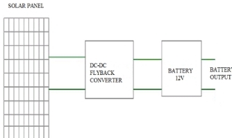
Fig. 1.0: Simplified block diagram of the model.
1.7 DEFINITION OF TERMS
RELAY: This is an electromagnetic switch. Switching on/off of relays is based on the flow of current through its coil. Relay is used for switching on/off various high voltage circuits. Changeover switch.
TRANSFORMER: This a device used for stepping up and down of voltages. Transformer is one of the most important components of the automatic changeover switch. The job of the transformer is to step down 220v to15v as the output of the automatic changeover switch.
RECTIFIERS: The rectifier circuit consists of a rectifies in series with the AC input to rectifies and the load requiring the DC output i.e. it convert AC to DC.
DIODE: These are two terminal devices which exhibit low resistance to current flow in one direction and hinder resistance to resistance to current in the other direction. Diode is electronic components.
CAPACITORS: These are passive components that provide a means of storing electrical energy in form of an electric field.
REGULATOR: These are device that are used control the rate of current or voltage that from in a process.
LIGHT EMITTING DIODE (LED): This is a small semiconductor devices which emit light when small forward current is applied to them.
RESISTORS: These are defines as devices that alter or resist the flow of current in an electric circuit.
POWER OUTAGE/ POWER FAILURE: is the loss of the electrical power network supply to an end user.
AUTOMATIC CHANGEOVER: is device that automatically transfers power from generator supply to PHCN supply when available and stops the generator without human intervention.
CHAPTER TWO
2.0 LITERATURE REVIEW
2.1 RENEWABLE ENERGY
Renewable energy is energy created from natural sources. This includes sunlight, wind, rain, tides and geothermal heat. With global warming, such as climate change, concerns linked to high oil prices, the drive for more renewable energy is being lobbied by local governments (Ch. Brunner, 2002). Not only would renewable energy help with the global warming concerns, but also may help turn around the recent economic crisis. This would mean less money spent on expensive fossil fuels and more focus on renewable energy sources. So world energy now requires renewable sources to sustain more power accuracy in future. Among the natural sources sunlight is more essential to mankind. Using this source power can be generated within cheap rate (M. Gohul, et al., 2009). Power failure in Bangladesh is a major issue and this condition is degrading with time. People are making themselves dependent on power backup machines such as Instant Power Supply (IPS), generator, Uninterruptible Power Supply (UPS) etc. These machines have a high market value and besides they require expensive maintenance such as fuelling the generator at regular interval, high electricity bill for charging an IPS, checking the distilled water in IPS. Still there are many rural areas in third world countries where the power transmission lines have not been provided yet. As a consequence people leaving over those areas have no other way but to suffer from lack of electricity using the energy of sun, solar panels at home, is the best solution to all these problems. To make this system more efficient and cost-effective it is better to use a dc-dc converter to charge a battery instead of using a simple charge controller (Sabuj D.G., et al., 2014).
There are some conventional charge controllers, which have some problems of charging system. So these charge controllers cannot charge batteries at some extent. To overcome these problems a new type of dc to dc converter, naming fly back converter has been introduced. A block diagram of the conventional charge controller is given below:
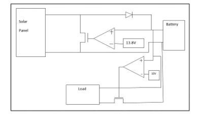
Fig. 2.1: Conventional charge controller.
The conventional charge controller of solar home system has the following disadvantages:
- it provides inadequate current during low sunlight.
- It cannot support a solar panel of high voltage.
- In the conventional charge controller excessive power loss occurs in the transmission line between solar panel and charge controller.
- In the conventional system the panel gets shorted when the battery is completely charged, which affects the panel longevity.
- In this circuit MPPT (Maximum Power Point Tracking) cannot be introduced (Sabuj D.G., et al., 2014).
To overcome these shortcomings, a new type of dc to dc converter (fly back converter) is introduced. The advantages of using this converter over the conventional charge controller are:
- It can take variable panel voltage.
- Its efficiency is better than the conventional one as it reduces wire loss.
- It is suitable for micro-grid.
- No panel- short circuit occurs here.
- It is possible to add MPPT (Maximum Power Point Tracking) with our system (Sabuj D.G., et al., 2014).
2.2 OVERVIEW
A charge controller is needed in photovoltaic system to safely charge sealed lead acid battery. The most basic function of a charge controller is to prevent battery overcharging. If battery is allowed to routinely overcharge, their life expectancy will be dramatically reduced. A charge controller will sense the battery voltage, and reduce or stop the charging current when the voltage gets high enough. This is especially important with sealed lead acid battery where we cannot replace the water that is lost during overcharging. Unlike Wind or Hydro System charge controller, PV charge controller can open the circuit when the battery is full without any harm to the modules. Most PV charge controller simply opens or restricts the circuit between the battery and PV array when the voltage rises to a set point. Then, as the battery absorbs the excess electrons and voltage begins dropping, the controller will turn back on. Some charge controllers have these voltage points factory-preset and non-adjustable, other controllers can be adjustable (German, 2016).
Electricity generations of solar panels are strongly related with solar radiation intensity. However the intensity is not stable. Therefore, charge efficiency is a very important topic in solar systems. Charge controllers are designed to improve charge efficiency and safety. The figure 2.2 below shows the front view of a typical charge controller:
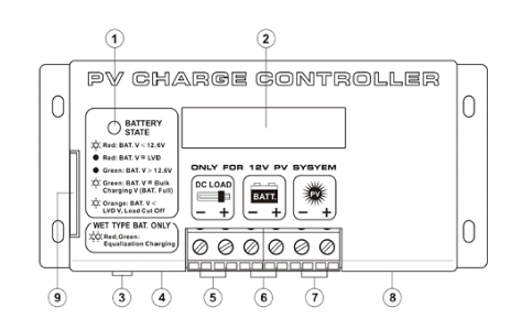
Fig. 2.2: Front View of a PV Charge Controller
[source: intelligent charge controller design]
Where:
- Battery LED indicator
- LCD display
- Reset button
- Temperature sensor
- 12V DC load terminal with Low Voltage Disconnect
- 12V battery connection terminal
- PV panel connection terminal
- Remote Signal Terminal
- Side Door (open to access switches for settings)
2.2.1 REVIEW OF THE EXISTING THEORY IN SOLAR CHARGE CONTROLLER POWER SYSTEM
The primary function of a charge controller is to protect the battery from overcharge and over discharge in a stand-alone PV system (REN, 2016). There are a lot of studies about the charge controller in the literature.
Harrington and Dunlop (1992) analyzed the typical strategies for battery charge regulation in stand-alone PV systems and conclude that the battery information is very important in designing PV systems. Ullah focused on the design of a super-fast battery charger based on Nationals proprietary neural network based neural fuzzy technology in 1996. They compared their method with conventional fast chargers and indicate that their method reduce the charging time (Tam Hunt, 2015).
Masheleni and Carelse in 1997 designed an intelligent charge controller, incorporating an SGSThompson microcontroller, ST62E20 and discussed the advantages of such charge controllers. Hsieh in 2001 proposed a fuzzy-controlled active state of- charge controller (FC-ASCC) for improving the charging behaviour of a lithiumion (Liion) battery. In this method, a fuzzy-controlled algorithm is built with the predicted charger performance to program the charging trajectory faster and to remain the charge operation in a proposed safe-charge area (SCA). They increased the charging speed about 23%. Yi presented a novel switch-mode charger controller IC in 2007 for improve the charging efficiency of valve regulated lead-acid (VRLA) battery and save its life.
They achieved fast transient response and the precisions of both constant current and constant voltage charge modes met the specifications well (Bullis, K., 2006).
Chiang (2009) presented the modeling and controller design of the PV charger system implemented with the single-ended primary inductance converter (SEPIC) and gave a detailed modeling of the SEPIC with the PV module input and peak-current-mode control. The system has been proved to be effective in the MPPT and power balance control. The MPPT controller was implemented with the Matlab real-time control in their study.
Tesfahunegn (2011) proposed a new solar/battery charge controller that combines both MPPT and overvoltage controls as single control function. They conducted two case studies in Simulink/Simpower, first to evaluate the performance of the designed controller in terms of transient response and voltage overshoot. Secondly, realistic irradiance data is used to evaluate the performance of the developed charge controller in terms of parameters such as PV energy utilization factor and overvoltage compared to the conventional hysteretic on/off controller. They achieved good transient response with only small voltage overshoot, better in terms PV energy utilization and same level of overvoltage control (Bazilian M. et al., 2013).
Dakkak and Hasan (2012) analyzed a charge controller based on microcontroller in stand-alone PV systems and concluded that such systems reduce the power consumption for charging battery and give flexibility to the designer (Swanson, 2009).
Karami (2012) focused on the load type and suggest new methods to reach the MPP depending on the load state and the development of the PV array mathematical model. They analyzed the effect of temperature and irradiance on the battery charger and showed the difference between the direct-coupled and the indirect-coupled applications of a PV panel (Branker, K. et al., 2011).
2.3 SYSTEM DESCRIPTION
In the review of a charge controller, one must not fail to mention that the charge controller is a part of the solar family set-up and this solar family set-up make up the complete system description. This solar family setup is briefly reviewed below and consists of:
- Solar panel
- Battery
- Charge controller
- Maximum Power Point Tracker
- DC DC converter
2.3.1 Solar Panel
A solar panel is a packaged connected assembly of photovoltaic cells. The solar panel can be used as a component of a larger photovoltaic system to generate and supply electricity in commercial and residential applications. Solar panels use light energy photon from the sun to generate electricity through the photovoltaic effect. The majority of modules use wafer based cells or thin film cells based on non-magnetic conductive transition metals, telluride or silicon. Electrical connections are made in series to achieve a desired output voltage and or in parallel to provide a desired current capability. The conducting wires that take the current off the panels may contain silver, copper or other nonmagnetic conductive transition metals. The cells must be connected electrically to one another and to the rest of the system. Each panel is rated by its DC output power under standard test conditions, and typically ranges from 100 to 320 watts. Depending on construction, photovoltaic panels can produce electricity from a range of light frequencies, but usually cannot cover the entire solar range (specifically, ultraviolet and low or diffused light).
Hence, much of the incident sun light energy is wasted by solar panels, and they can give far higher efficiencies if illuminated with monochromatic light. The figure below shows the interconnection of solar panels.
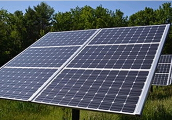
Plate 2.3: Interconnection of solar panels [source: Fort Benning Solar]
The advantages of solar panels are:
- They are the most readily available solar technology.
- They can last a lifetime.
- They are required little maintenance.
- They operate best on bright days with little or no obstruction to incident sunlight.
2.3.2 Battery
In stand-alone photovoltaic system, the electrical energy produced by the PV array cannot always be used when it is produced because the demand for energy does not always coincide with its production. Electrical storage batteries are commonly used in PV system. The figure below shows a typical 12V 200Ah solar battery:
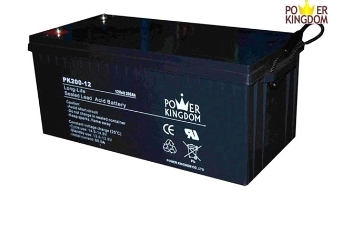
Plate 2.4: A typical solar battery [source: kingdom power company]
The primary functions of a storage battery in a PV system are:
- Energy Storage Capacity and Autonomy: to store electrical energy when it is produced by the PV array and to supply energy to electrical loads as needed or on demand.
- Voltage and Current Stabilization: to supply power to electrical loads at stable voltages and currents, by suppressing or smoothing out transients that may occur in PV system.
- Supply Surge Currents: to supply surge or high peak operating currents to electrical loads or appliances.
2.3.3 Charge Controller
A charge controller or charge regulator limits the rate at which electric current is added to or drawn from electric batteries. It prevents overcharging and may prevent against overvoltage, which can reduce battery performance or lifespan, and may pose a safety risk. It may also prevent completely draining (“deep discharging”) a battery, or perform controlled discharges, depending on the battery technology, to protect battery life. The figure 2.5 below shows a typical charge controller.
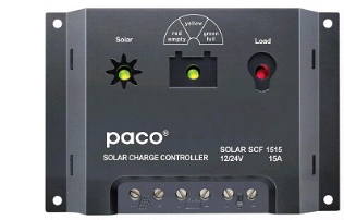
Plate 2.5: A typical charge controller [source: china solar power]
In simple words, Solar Charge controller is a device, which controls the battery charging from solar cell and also controls the battery drain by load. The simple Solar Charge controller checks the battery whether it requires charging and if yes it checks the availability of solar power and starts charging the battery. Whenever controller found that the battery has reached the full charging voltage levels, it then stops the charging from solar cell. On the other hand, when it found no solar power available then it assumes that it is night time and switch on the load. It keeps on the load until the battery reached to its minimum voltage levels to prevent the battery dip-discharge (Encyclobeamia.solarbotics.net). Simultaneously Charge controller also gives the indications like battery dip discharge, load on, charging on etc.
In this design we are using microcontroller based charge controller. Microcontroller is a kind of miniature computer containing a processor core, memory, and programmable input/output peripherals.
The Functions of a microcontroller in charge controller are:
- Measures Solar Cell Voltage.
- Measures Battery Voltage.
- Decides when to start battery charging.
- Decides when to stop battery charging.
- Decides when to switch on the load.
- Decides when to switch off the load.
- Most importantly in this design, microcontroller also tracks the MPP of the output power.
2.3.4 Maximum Power Point Tracker
The maximum power point tracker (MPPT) is now prevalent in grid-tied PV power system and is becoming more popular in stand-alone systems. MPPT is a power electronic device interconnecting a PV power source and a load, maximizes the power output from a PV module or array with varying operating conditions, and therefore maximizes the system efficiency (www.Encyclobeamia.solarbotics.net.).
MPPT is made up with a switch-mode DC-DC converter and a controller. For grid-tied systems, a switch-mode inverter sometimes fills the role of MPPT. Otherwise, it is combined with a DC-DC converter that performs the MPPT function.
2.3.5 DC-DC Converter
DC-DC converters are power electronic circuits that convert a dc voltage to a different dc voltage level, often providing a regulated output. The key ingredient of MPPT hardware is a switch-mode DC-DC converter. It is widely used in DC power supplies and DC motor drives for the purpose of converting unregulated DC input into a controlled DC output at a desired voltage level.
MPPT uses the same converter for a different purpose, regulating the input voltage at the PV MPP and providing load matching for the maximum power transfer. There are a number of different topologies for DC-DC converters. In this design we are using DC-DC converter as it is obtained by using the duality principle on the circuit of a boost converter (www.Encyclobeamia.solarbotics.net.).
2.4 THE CHARGE CONTROLLER
2.4.1 Working Principle of a Charge Controller
The basic components of a solar charge controller (especially that used for this design) are:
- Microcontroller
- Boost converter
- MOSFET
- Voltage sensor
- Liquid Crystal Display (LCD)
- Light Emitting Diode (LED)
There are other components like the power inductor, capacitors, resistors, diodes etcetera. The working circuit diagram is shown in the figure below:
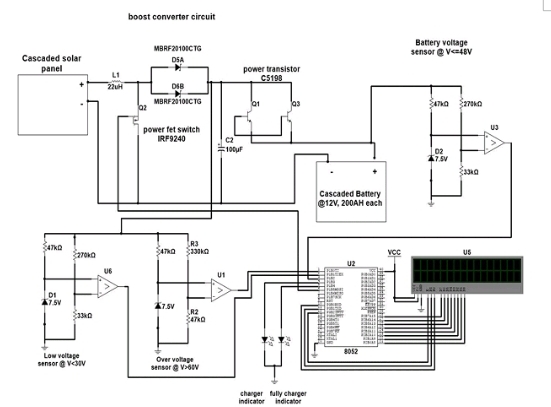
Figure 2.6: Working circuit diagram of a charge controller (source: solar energy Centre)
From the circuit diagram above, it can be seen that the voltage from the solar panel first comes to the boost converter circuit which does the job of stepping up the input DC voltage to get a higher DC output voltage if the input voltage is lower than the specified rating (12V in this case). The boost converter is connected to the voltage sensor which is further interconnected to the microcontroller. The function of the microcontroller has already been established earlier in this chapter.
The LED indicates when the charge controller is charging the battery and when it is fully charged while the LCD displays the battery voltage and panel input voltage. Generally, there are two types of charge controllers namely:
- The Pulse Width Modulation (PWM)
- The Maximum Power Point Tracking (MPPT)
2.4.2 Pulse Width Modulation Charge Controller
Pulse Width Modulation (PWM) charge controllers are simple and more affordable. It uses a series of pulses to charge the battery. It regulates the voltage by varying the width of the pulse. If it wants to increase the voltage, it increases the pulse width and when it wants to lower the voltage, it reduces the pulse width (Palz, W., 2013).
The technology behind Pulse Width Modulation (PWM) charge controllers is one of the most popular charge controller technologies on the market today. A time-tested technology that has been used for many years in solar photovoltaic (PV) systems with batteries, it is also needed for wind, hydro, fuel, or utility grid. PWM charge controllers are inexpensive (when compared to MPPT charge controllers), available in different amperages, and highly durable. PWMs help to regulate often inconsistent voltage put out by power sources (for example solar panels) in order to protect the system batteries from overcharging. When the solar array has the PWM mode activated, the charge controller uniquely handles the job of battery charging by constantly checking the current battery and self-adjusting accordingly to send only the right amount of charge to the battery.
This type of charge controller works by reducing the current from the power source according to the batterys condition and recharging requirements. The PWM charge controller does this by checking the state of the battery to determine both how long (wide) the pulses should be as well as how fast they should come (Jacobson, M.Z. 2009). With this information, the PWM charge controller then self-adjusts and sends the appropriate pulse to charge the battery it varies the length and speed of the pulses sent to the battery as needed. This is a rapid on and off switch. When the battery is nearly discharged, the pulses may be long and continuous, and as it becomes charged, the pulses become shorter or trickled off. This trickle or finish type charging mode is important for systems that can go days or weeks with excess energy during periods when very little of the solar energy is consumed (Jacobson, M.Z. 2009).
This type of charge controller is ideal for solar arrays where excess energy is a regular occurrence, and provide several key benefits: higher charging efficiency, rapid recharging, and healthier batteries that operate at full capacity.
2.5 BENEFITS OF USING A PWM CHARGE CONTROLLER
Traditional systems for charging solar system batteries relied on on-off regulators to limit battery out gassing during periods of excess energy production, but this often resulted in early battery failures and increased load disconnects. With a PWM algorithm, the charge controller can slowly reduce the charging current to prevent problems like gassing and overheating of the battery (Jacobson, M.Z. 2009). The benefits are thus:
- Battery Aging Adjustments: By automatically adjusting to the batterys needs, a PWM charge controller will overcome traditional problems with charge acceptance seen in older batteries.
- Battery Gassing and Heat Reductions: By recharging more quickly than other charge controllers, a PWM avoids problems with gassing and heating which damage the battery.
- Charge Acceptance Increase: Charge acceptance is a necessity with solar system batteries, though this has typically been a problem in solar arrays. A PWM algorithm, however, increases the charge acceptance of the battery so that more of the energy generated by the array gets captured.
- Drifting Battery Cell Equalization: Many PWM charge controllers hold battery cells in better balance through equalization, which evens out the acceptance of charge to avoid capacity deterioration.
- High Battery Capacity Maintenance: The state-of-charge should remain high in order to maintain a healthy system and preserve the life of the battery. PWM algorithms provide better battery capacity maintenance due to the increased number of charge/discharge cycles.
- Lost Battery Recovery: Sulfation of lead-acid batteries in solar systems is a significant problem due to extended undercharging, which results in grid corrosion and sulfate crystal formation on the batterys positive plates. PWM charge controllers have been shown to recover lost capacity over time by deterring sulfate deposit formation, and pushing through corrosion at the interface.
- Self-Regulation with Drops in Voltage or Temperature: Older charge controllers can be negatively impacted by temperature effects or voltage drops, creating problems with the final charge of the battery. But a PWM charge controller will taper the charge to minimize these impacts.
- Taken together, these PWM advantages can be very attractive to PV owners looking for a simpler way to manage their solar set-up.
2.5.1 Maximum Power Point Tracker Charge Controller
The MPPT charge controller tries to keep the voltage and the power stable. The MPPT charge controller will harvest more power from the solar array it will adjust its input voltage to harvest the maximum power from the solar array and the transform this power to supply the varying voltage requirement of the battery plus load (Jacobson, M.Z. 2009).
An MPPT charge controller is an electronic DC to DC converter that optimizes the match between the solar array (PV panels), and the battery bank or utility grid. To put it simply they convert a higher voltage DC output from solar panels down to the lower voltage needed to charge batteries or vice-versa. Maximum Power Point Tracking is electronic tracking usually digital. The charge controller looks at the output of the panels, and compares it to the battery voltage. It then figures out what is the best power that the panel can put out to charge the battery. It takes this and converts it to the best voltage to get maximum amps into the battery. Most modern MPPTs are around 93-97% efficient in the conversion (Jacobson, M.Z. 2009).
The power point tracker is a high frequency DC to DC converter. They take the DC input from the solar panels, change it to high frequency AC, and convert it back down to a different DC voltage and current followed by the output regulator to exactly match the panels to the batteries. MPPTs operate at very high audio frequencies, usually in the 20-100kHZ range. The advantage of high frequency circuits is that they can be designed with very high efficiency transformers and small components. The design of high frequency circuits can be very tricky because of problems with portions of the circuit broadcasting just like a radio transmitter, causing radio and TV interference. Noise isolation and suppression becomes very important.
2.5.2 Effectiveness of the MPPT
MPPTs are most effective under these conditions:
- Winter, and/or cloudy or hazy days – when the extra power is needed the most.
- Cold weather – solar panels work better at cold temperatures, but without a MPPT you are losing most of that. Cold weather is most likely in winter – the time when sun hours are low and you need the power to recharge batteries the most.
- Low battery charge – the lower the state of charge in your battery, the more current an MPPT puts into them – another time when the extra power is needed the most. You can have both of these conditions at the same time.
- Long wire runs – If you are charging a 12 volt battery, and your panels are 100 feet away, the voltage drop and power loss can be considerable unless you use very large wire. That can be very expensive. But if you have four 12V panels wired in series for 48 volts, the power loss is much less, and the controller will convert that high voltage to 12 volts at the battery. That also means that if you have a high voltage panel setup feeding the controller, you can use much smaller wire.
2.5.3 Smart Power Trackers
Charge controllers for solar panels need to be a lot more smart as light and temperature conditions vary continuously all day long, and battery voltage changes All recent models of digital MPPT controllers available are microprocessor controlled. They know when to adjust the output that is being sent to the battery, and they actually shut down for a few microseconds and look at the solar panel and battery and make any needed adjustments.
Although not really new (the Australian company AERL had some as early as 1985), it has been only recently that electronic microprocessors have become cheap enough to be cost effective in smaller systems (less than 1kW of panel). MPPT charge controllers are now manufactured by several companies, such as Outback Power, Xantrex XW-SCC, Blue Sky Energy, Apollo Solar, Midnite Solar, Morningstar and a few others (Jacobson, M.Z. 2009).
2.5.4 Preference of MPPT Charge Controller over PWM for the design
MPPT is at least 30% more efficient than PWM. PWM have been around for ages and rely on old technology. They work to match the voltage of the panel to battery voltage and pulls down the panel output voltage in doing so.
Another downside to the PWM is that it also creates interference in radios and TVs due to the sharp pulses that it generates.
The MPPT charge controllers offer a potential increase in charging percentages, offers up to 80 amps sizes, MPPT charge controller warranties are typically longer than PWM and offer great flexibility for system growth.
CHAPTER THREE
3.0 RESEARCH METHODOLOGY
3.1 Brief Outline of the Chapter
This chapter includes the research methodology, different forms of component that make up the solar photovoltaic system such as the battery bank, the solar charger controller and the load (appliance) were. Also discussed.
3.2 RESEARCH DESIGN
The first step in understanding a solar photovoltaic system is to find out total power and energy consumption of all loads that are needed to be supplied by the solar photovoltaic system as follow:
Calculating the total watt hour per day needed from the photovoltaic modules.
This is done by multiplying the total appliances with hours per day the energy loss factor in the system to get total watt- hours per day which must be delivered to the appliances.
These following stages were adopted:
- Power supply
- Power Transformer
- Voltage Regulator
- The Inverter Stage
- Inverter Sizing
POWER SUPPLY
All electronic equipment needed to be energized by means of electric power supply. An inverter uses a 12V accumulated battery.
It supplies 12V to the input of the voltage regulator that regulates it to a stable and constant supply to power the control circuit.
POWER TRANSFORMER
A transformer is a device of two coils called primary and secondary coil. The Alternating Current voltage applied to the primary coil appears across the secondary coil by electromagnetic induction.
Power transformers convert incoming Alternating current (AC) power from the incoming voltage to a different voltage by a process called electromagnetic induction, the generation of an electric current by passing metal wire through a magnetic field used in electronic circuit; they generally provide power to an electronic device at a steady voltage, solving the problem of voltage fluctuation (Electrical 4u (2014).
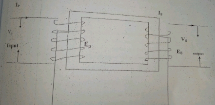
Fig. 3. 1 Transformer
If the input (primary) has more turn than the output, the secondary voltage is smaller than the primary voltage.
Ns =number of turn in secondary
Np=number of turn in primary
Ep=primary voltage / input voltage
Es=secondary voltage / output voltage
Is=secondary current
Ip=primary current
Ns/Np=Es/Ep=Ip/IsVOLTAGE REGULATOR
A voltage regulator is piece of equipments designed for the maintenance of a constant level of voltage. Several types of voltage regulator exist and has their own advantages and disadvantages. Most voltage regulator work by using an internal fixed voltage as a reference to be compared to the voltage being put out.
Voltage regulator is an integrated circuit component that gives a constant output voltage supply. Voltage regulator can be divided into fixed and adjustable regulator. The three terminals of the fixed voltage regulator are the input, common and the output terminals while those of the adjustable voltage regulator are the input, output and adjustment terminals.
There are four types of voltage regulator
SERIES PASS VOLTAGE REGULATOR
Series pass regulators are considered the least effective of voltage regulator. Its power is continuously dissipated. Thus making it more reliable than other type.
SHUT VOLTAGE REGULATOR
They are more efficient than the series types because, their power is usually none dissipated until the battery approaches full capacity.
STEP DOWN SERIES SWITCH REGULATOR
The step down series switch regulator, like the series type regulator, increases efficiency at the voltage output increases. The increases complexity of the circuitry, however, makes this type less reliable than either the series pass or shut type.
STEP-UP SHUT SWITCHING REGULATING
It has the highest efficiency as a result of its complex circuitry. That complexity makes the cost of this type of regulator so high that its impractical to use for certain purposes.
COMPONENT OF VOLTAGE REGULATOR
- Capacitor
- Resistor
- Diode
- Transistor
THE INVERTER STAGES
The inverter unit is made of, sourcing, regulating, oscillating, driving, transformation, output, change over, battery charger, and MOSFET driver.
SOURCING STAGE: This stage consists mainly of direct current (D.C) battery and in this case is from solar panel . The battery provides 12V direct current (D. C) supply to the inverter system when the alternating current (A. C) from the main supply fails.
REGULATING STAGE : The regulating stage consists of an Integrated Circuit voltage regulator. This is a three pm 9V. integrated Circuit voltage regulator it is a simple precision regulator that regulates the supplied voltage of 12V from battery. The regulated voltage is then used by the oscillator to come on.
OSCILLATING STAGE: The oscillating stage is the heart of inverter design. An oscillator is essentially an electronic circuit designed to produce an alternating current signal of the known frequency and wave form. The inverter system needs to generate signal at 50Hz as which is sent driver for amplification through the pin 11 and 14 Integrated Circuit.
DRIVING STAGE: The driving stage is required to drive the current derived from the output of the oscillator to the amplifier. The stage consists of metallic oxide semiconductor field effect transistor (MOSFET) which has high impedance.
The transistor user are both PNP and NPN transistor which are connected in a push-pull arrangement. The MOSFET driver stage does not match the oscillator to amplifier but also ensure that the stage of the MOSFET when in parallel are properly isolated from each other even when they are driven by the gate of the MOSFETs which result in the MOSFETS channel being alternatively switched on and off. That its when one second MOSFET channel which is a crucial process in the outlet section is repeatedly 50 tons per seconds that is at frequency of 50Hz.
TRANSFORMATION STAGE: Here, a step-up transformer is used. It is a type of transformer used for increasing voltage supply to the output. The step-up transformer consists of two coils called primary and secondary coils, wounded round a soft iron that is made of sheet of soft iron.
The secondary coil of this type of transformer is however greater than the number of turns in the primary coil.
The primary winding of the step-up transformer is 24V-0V-240V and the secondary winding is transferred to the socket outlet of the output of the inverter system.
OUTPUT STAGE: In this stage, the Alternating Current voltage produced by the inverter reaches socket output the action of the pulse width modulation (PWM) of the Integrated Circuit, Also, the expected load is connected through this socket outlet so as to power it.
CHANGE OVER STAGE: The change over stage takes the center stage when the alternating current main supply is off, then the yellow led indicator comes on indicating that the inverter has started to operate on the battery mode and when the alternating current supply returns, the green led indicator is on then inverter.
SOLAR CHARGED CONTROLLER SIZING
The solar charge controller is typically against amperage and voltage of photovoltaic away and batteries then identify which type of solar charge controller is right for the application. The solar charge controller must have enough capability to handle the current from photovoltaic arrays.
For the series charge controller type, the sizing of controlled depends on the total photovoltaic input current which is delivered to the controller and depends also or photovoltaic panel configuration (series or parallel configuration). According to the standard practice, the sizing of solar charge controller is to take the start circuit (ISC) of the photovoltaic array and multiply it by 1.3 solar charge controller =(total short circuit current rating of VP x 1.3)
3.3 BLOCK BY BLOCK (UNIT BY UNIT BLOCK DIAGRAM OF THE PROJECT)
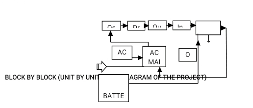
Fig. 3.2 Block Diagram of a solar battery charger
If you find this post helpful, please share it and spread the word! Want more content like this? Sign up for our newsletter to receive helpful Tips
Related blog
→ PROJECT WRITE-UP FOR FABRICATION AND INSTALLATION OF WORKSHOP METAL DOOR 2022
Siwes report on computer engineering – free write-up→
HOW TO WRITE A TECHNICAL REPORT ON STUDENT INDUSTRIAL WORK EXPERIENCE SCHEME (SIWES)