
ELECTRONIC VOLTMETERS
A significant improvement in performance can be realized when a meter is driven by an amplifier. The amplifier offers more sensitive ranges and higher input resistances than can be obtained with a simple meter and range multiplier resistors. The input resistance of an electronic amplifiers is usually high enough that correction for loading effect upon the network under test is not required. Typical accuracies range from 0.5% to several percent. There are two basic types of electronic d.c voltmeters are direct-coupled and chopper type amplifier d.c voltmeters.
(a) A.c voltmeter with direct- coupled amplifier
Fig. 4.1 gives the block diagram of direct-coupled amplifier d.c voltmeter. It consists of an attenuator, multistage d.c amplifier and a d.c (moving coil meter) to indicate the d.c voltage. The d.c voltmeter with direct-coupled amplifier is generally used in low priced electronic meters. Fig.4.2. gives a schematic diagram of a simple d.c voltmeter using d.c amplifier. The first stage of amplifier is FET amplifier to get high inputs impedance. This FET stage effectively isolates the meter circuit from the circuit under measurement.
Two NPN transistor Q2 and Q3 form a direct coupled d.c amplifier. The input FET stage drives this d.c amplifier while the output of the d.c amplifier drives the d.c meter. The d.c meter deflection is directly proportional to the applied input voltage. The meter is calibrated to indicate the d .c input voltage.
Fig.4.1. Block diagram of direct-coupled amplifier d.c voltmeter
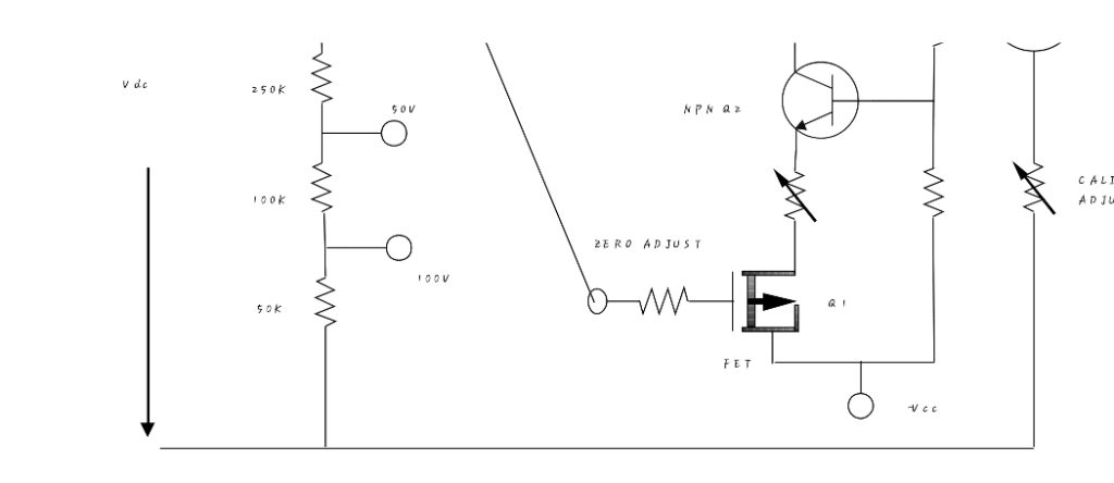
Fig. 4.2 schematic diagram of direct coupled amplifier d.c voltmeter Merits of direct-coupled amplifier d.c voltmeter
- High input impedance
- Protection from accidental input overload. In case of an overload, d.c amplifier gets saturated and limits the maximum current through the meter.
- Chopper-type amplifier d.c voltmeter
(b) Chopper-type amplifier d.c voltmeter
D.C voltmeter with chopper-type amplifier is used in highly sensitive d.c voltmeters with highly stable d.c amplifiers. In these d.c amplifiers, the d.c input voltage is first converted into a.c voltage by a chopper modulator. The resulting a.c voltage is then amplified in an a.c amplifier. The amplified a.c voltage is demodulated to get the d.c voltage proportional to the original input d.c voltage.
The demodulator chopper is used in synchronism with the modulator chopper. A low pass filter removes residual a.c voltage. The block diagram is shown in fig. 4.3. Fig. 4.3. Block diagram of chopper type amplifier d.c voltmeter
4.1 ELECTRONIC A.C VOLTMETER
The two basic types of electronic a.c voltmeters are rectifier amplifier and amplifier rectifier electronic a.c voltmeter.
In the rectifier amplifier electronic a.c voltmeter, the a.c voltage is first rectified and then fed to an electronic d.c voltmeter. This type of amplifier provides a relatively cheap instrument and is used in most of the low price electronic a.c voltmeter. In this instrument, the rectifier unit may be enclosed in the voltmeter itself. However, quite often, the rectifier unit is constructed as an a.c probe whose output is fed to the electronic d.c voltmeter through a shielded cable. The probe includes a half wave rectifier and RC filter to remove ripple voltages. While in amplifier rectifier a.c voltmeter, the a.c voltage is first amplified in an a.c amplifier and rectified before being fed to an electronic d.c voltmeter.
The block diagrams are shown in fig. 4.4 (a) and (b) respectively. Fig.4.4 (a) Rectified-amplified electronic a.c voltmeter Fig.4.4 (b) Amplified-rectified electronic a.c voltmeter
4.5 DIFFERENTIAL VOLTMETER
This is a null method of determining an unknown voltage. The unknown voltage is compared to a known voltage. This is done by adjusting the potentiometer to obtain zero (or minimum) deflection in the null detector. Under this condition, the unknown voltage is equal to the voltage output of the potentiometer. A simplified block diagram of the differential voltmeter using the principle of operation of potentiometer is shown in the fig.4.5.
The unknown d.c voltage is applied through an attenuator to the high gain negative feedback d.c amplifier. A fraction of the output of the amplifier, which must in no case be more than 1V, is fed through a voltage divider to the input of the differential amplifier; the other input of which is fed by a 1V reference supply. The difference of the two voltages is indicated by the null meter.
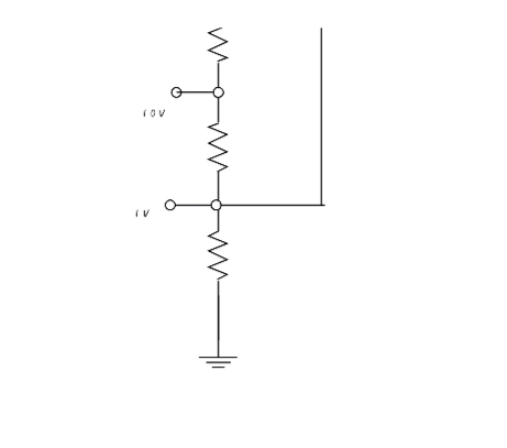
Fig. 4.5 block diagram of differential voltmeter mode of operation
4.3 DIGITAL VOLTMETER
Digital voltmeter display measurement as discrete numerals rather than as a pointer deflection on a scale commonly used in analog voltmeters. Due to the numerical readout most of the human errors, such as interpolation and parallax errors are eliminated and reading speed is increased. The two basic digital voltmeter are voltage-to-time ramp type and stair case-ramp type digital voltmeter.
- Voltage-to-time ramp type and stair case-ramp type digital voltmeter
The operating principle of voltage-to-time ramp type and stair case-ramp type digital voltmeter is the measurement of time for a linear ramp to change from input level to zero or ground. This interval of time is proportional to the unknown voltage at the input. The block diagram in fig. 4.7 illustrates the basic components of a voltage -to- time ramp type digital voltmeter system.
The unknown voltage to be measured is applied to the input comparator. When the internal ramp and the pulse which allows pulse to enter the counter. A stop pulse is generated by the ground comparator when the ramp coincides with zero volts. At this time no more pulse enter into the counter. The content of the counter are transferred to the visual readout with the results of the measurement. At the end of the period the counter is reset to zero and the linear ramp is regenerated, thus starting a new measurement cycle.
Fig.4.6 Block diagram of a voltage-to-time ramp type and stair case- ramp type digital voltmeter.
2. Stair case-ramp type digital voltmeter.
The basic stair case-ramp type digital voltmeter converter system generates a precise voltage stair case whose step corresponds to the list significant digit of the measurement. The basic technique is illustrated in fig. 4.8. At the start of the measurement, a start pulse opens a gate to allow clock to enter a counter and be counted. The outputs of the counter are connected to a digital-to-analog converter whose voltage level output is proportional to its digital input. As each pulse is entered into the counter, one is added to the least significant digit, and correspondingly the output of the digital-to analog converter is incremented by one least significant step in the stair case ramp. The input is compared with this internally generated ramp. When the comparator detects coincidence, the counter is stopped and its contents are transferred to a visual readout device. The content of the counter are proportional to the unknown input voltage.Fig. 4.7 Block diagram of a stair case-ramp type digital voltmeter.
4.4 WAVE ANALYZER
Wave analyzer is an instrument which can be used to measure the magnitude of the various harmonics of a complex wave directly. The wave analyzer can be used to measure low and high frequency waves. The wave analyzers are as follows;
- Simple wave analyzer.
- Frequency-selective wave analyzer.
- Hl Heterodyne wave analyzer.
The frequency-selective wave analyzer and heterodyne wave analyzer are used for high frequency analyzer while simple wave analyzer is used for low frequency analyzer. But in this lecture note heterodyne wave analyzer will only be discussed.
Heterodyne wave analyzer.
This is a very popular wave analyzer used in the MHz range, particularly suited to higher frequencies. The input signal to be analyzed is heterodyned by an internal local oscillator. The output of the first mixer is fed to a highly selective multistage amplifier with a predetermined fixed frequency. The frequency of the internal local oscillator is adjusted so that the difference frequency between the frequency of the local oscillator and that of the desired component of the signal under test is equal to the resonant frequency of the selective amplifier. Thus, the desired component has its frequency transformed to the resonant frequency of the selective amplifier and is amplified by it. Undesired component of the signal are transformed to frequencies which are rejected by the selective amplifier.
Two types of selective amplifiers are generally used in heterodyned wave analyzers. While the first type employs a crystal filter, the second type uses a high Q-active filter.
The output of the selective amplifier is again heterodyne by a crystal oscillator having frequency of the selective amplifier. This results in a signal centered on a zero frequency. An active amplifier with controlled bandwidth then passes the selective harmonic component to an electronic voltmeter. A block diagram of a heterodyne analyzer is shown in fig.4.8.
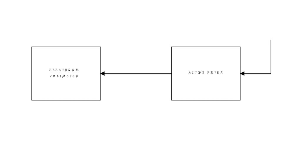
Fig.4.8. Block diagram of a heterodyne wave analyzer4.5 Harmonic Distortion analyzerIn practice, the output of electrical and electronic devices, such as a transformer and an amplifier are not pure sinusoidal signal even though the input signals are pure sinusoidal; the reason being the various types of distortion. The cause of distortion may be the inherent non-linear characteristics of the transformer and the transistors in the amplifier. The non-linear behavior of the devices introduces harmonics of the fundamental frequency in the output waveform, and the resultant distortion is, therefore, often referred as harmonics distortion. There is a well -known harmonic analyzer which are used to measure harmonic distortion.
4.6 Resonant-Circuit Harmonic Distortion Analyzer
A simple method of determining a harmonic content of the distorted wave is by using resonant-circuit shown In fig. 4.9. The series resonant circuit is turned to a particular harmonic frequency. The output of the coupling transformer is fed to the amplifier. The amplified harmonics are measured by a rectifier voltmeter which is calibrated in rms for a sinusoidal wave. After the voltmeter reading is taken, the analyzer is returned to the next harmonic frequency and reading is again taken. In this way the readings corresponding to all harmonics under consideration are noted. Fig. 4.9 resonant-circuit Harmonic Distortion Analyzer
4.7 SPECTRUM ANALYZER
The spectrum analyzer is an instrument that brings together a super heterodyne radio receiver with a swept frequency local oscillator and an oscilloscope to present a display of amplitude versus frequency. The spectrum analyzer is actually a super heterodyne receiver in which local oscillator is a sweep generator. A low frequency saw- tooth wave is applied to the sweep oscillator and the horizontal deflection plates of the cathode ray tube, producing a horizontal deflection that is a function of frequency. The lowest frequency is represented by left side of the trace while the highest frequency is represented by the side of the trace. The flg.4.11 shows a simple block diagram of a spectrum analyzer.Fig. 4.10 simple block diagram of a spectrum analyzerApplication of Spectrum Analyzer It is used to check the spectral purity of signal source.It is used to evaluate electromagnetic interference (EMI) problem.It is used to do surveys prior to installing radio receiving or transmitting equipment.It is used to test transmitters.It is used to analyze signatures.
Q-Meter This instrument is designed to measure some of the electrical properties of coils and capacitors by measuring the Q-value of an R-L-C circuit. The instrument essentially consists of;A frequency calibrated continuously variable RF oscillator. A calibrated variable capacitor C, VTVM which is calibrated to read Q- directly.The basic principle used in Q-meter is the resonant rise of the voltage across the capacitor in an R-L-C circuit. The condition for series resonance is XL =XC andE = IR. The value of the circuit is If the applied voltage E is constant, the Q is directly proportional to Ec. hence, by measuring voltage drop across C under resonant condition Q can be found vacuum tube-voltmeter can be used to measure the voltage or being calibrated directly to measure Q. The circuit diagram is shown in fig. 4.11.Fig. 4.11 Q-Meter For making measurement, the unknown coil is connected to the test terminals T of the instrument and the circuit is tuned to resonance. This is done (i) either by setting the oscillator to a given frequency and varying C or
(ii) by keeping value of C constant and adjusting the oscillator frequency. The reading on the VTVM must be multiplied by the index setting of the multiplying Q meter in order to obtain the actual value of Q.
APPLICATIONS OF Q-METER
Some of the specialized use of this instrument is to measure:The Q of a coil,Inductance and capacitanceDistributed capacitance of a coil, Q-factor and power factor of a dielectric material, Mutual inductance of a coupled circuits, Coefficient of coupling, Critical of coupling, Reactance and effective resistance of an inductor at operating frequency, Bandwidth of a tuned circuit etc.
MEASUREMENT METHOD OF Q-METER
Direct connection with the test terminals. Series connection with the working coil. Parallel connection with the working coil.
SOURCES OF ERROR
The most important error in measurement is due to the distributed capacitance of the coil. This capacitance in a coil changes the actual or effective Q.