
With the aid of a diagram state the principle of operation of cathode ray oscilloscope
Principle of Operation of a Cathode Ray Oscilloscope (CRO)
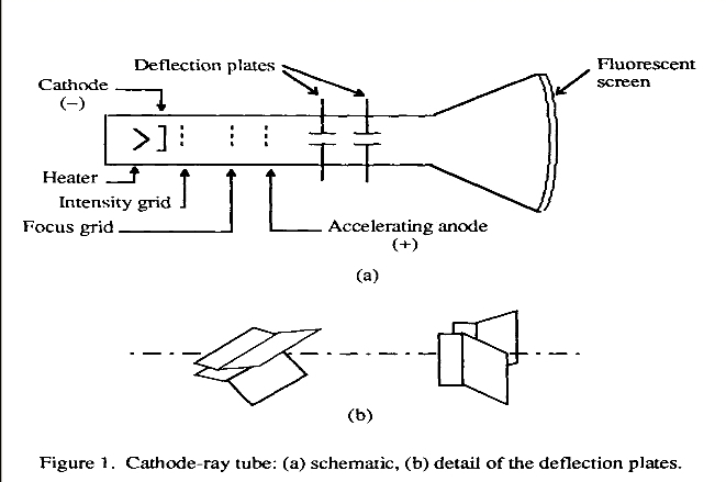
The Cathode Ray Oscilloscope (CRO) functions by manipulating an electron beam within a vacuum tube. An electron gun emits a stream of electrons, which is then accelerated and focused. This focused beam passes between two sets of deflection plates: horizontal and vertical.
Here’s a simplified diagram and explanation:
Key Components:
- Electron Gun:
- Emits a focused beam of electrons.
- Consists of a heated cathode that emits electrons, a grid to control the electron flow, and an anode to accelerate the electrons.
- Deflection Plates:
- Two sets of plates (horizontal and vertical) that create electric fields.
- The horizontal plates deflect the electron beam horizontally.
- The vertical plates deflect the electron beam vertically.
- Fluorescent Screen:
- A screen coated with a phosphor material that emits light when struck by electrons.
- The position of the bright spot on the screen represents the amplitude and waveform of the input signal.
Working Principle: - Electron Emission: The heated cathode emits electrons, which are accelerated towards the anode.
- Beam Formation: The emitted electrons are focused into a narrow beam by the grid.
- Horizontal Deflection: A varying voltage applied to the horizontal plates causes the electron beam to move horizontally across the screen.
- Vertical Deflection: Similarly, a voltage applied to the vertical plates deflects the beam vertically. The combination of these horizontal and vertical deflections, synchronized with the input signal, traces out the waveform of the signal on the fluorescent screen of the CRO. This visual representation allows for the analysis of various electrical signals, including voltage, current, frequency, and waveform shape.
- Display: The deflected electron beam strikes the fluorescent screen, producing a bright spot. The position of this spot on the screen represents the amplitude and waveform of the input signal.
In Summary:
The CRO works by converting electrical signals into visual representations on a screen. By applying voltages to the deflection plates, the electron beam is deflected in both horizontal and vertical directions, creating a visual representation of the input signal’s waveform.
Key Applications of CRO: - Measuring voltage and current
- Analyzing waveforms
- Measuring frequency
- Troubleshooting electronic circuits
- Observing transient signals
By understanding the basic principle of operation, you can effectively use a CRO to analyze and troubleshoot various electronic systems.
Describe the mode of operation of recorder in electrical science
A Deep Dive into Biomedical Recorders: Capturing Physiological Signals
Introduction:
In the realm of biomedical instrumentation, accurate data acquisition is paramount. Recorders play a pivotal role in capturing and preserving this valuable information. These devices can be broadly categorized into two primary types:
Analog Recorders: These devices directly record continuous variations in the input signal, reflecting the analog nature of physiological phenomena.
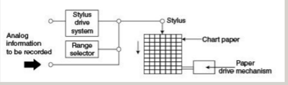
Graphic Recorders: Employ a stylus to trace variations of the input signal on moving chart paper, providing a visual representation of the signal over time.
Oscillographic Recorders: Utilize the deflection of an electron beam to display and analyze waveforms on a screen.
Magnetic Tape Recorders: Store analog signals on magnetic tape for later playback and analysis.
Digital Recorders: These devices convert analog signals into discrete digital values for storage and processing. They typically utilize an array of fixed recording elements, unlike conventional recorders that rely on moving pens or styluses. This approach enables precise reproduction of signals as discrete values at specific time intervals.
A Closer Look at Biomedical Recorders:
Let’s delve deeper into the intricacies of commonly employed biomedical recorders:
Strip Chart Recorder: This ubiquitous device comprises a moving strip of chart paper, a drive mechanism to regulate its movement, a stylus for marking the paper, and a stylus drive system to position the stylus in accordance with the input signal. This are instruments for the graph recording and portrayal of phenomena vary with respect to time. Strip chart recorder with data is recorded on a continuous roll of chart paper moving at a constant speed. The recorder records the variation of one of more variables with respect to time the basic element of a strip chart recorder consist of pen stylus and chart paper drive mechanism, chart speed selector switch.
Stylus Mechanisms:
Ink-filled Stylus: While convenient, it can be prone to clogging and is unsuitable for high-speed recording.
Heated Stylus: Melts a wax coating on the paper to create a visible trace.
Chopper Bars: Mark the paper using a specialized coating sensitive to electrical current.
Electric Stylus Marking: Utilizes electrical impulses to create marks on the paper.
Optical Marking: Employs a beam of light to write on photosensitive paper.
Galvanometric Recorder: This type of recorder leverages the principle of electromagnetic deflection. When a current flows through a coil placed within a magnetic field, the coil, along with the attached pen or stylus, deflects proportionally to the input signal. is a type of device used to measure and record electrical current it consists of a galvanometer, a pen attached to the galvanometer moving coil, and a rotating drum with a strip of paper attached to it. Electrical current to the measured is passed through the galvanometer causing the moving coil to detect as the coil deflects, the pen attached to it also moves creating a trace on the paper, attached to the rotating drum.
Key Components: There are 3 forces which act on the moving system
Deflecting Force: Generated by the current flowing through the coil.
Controlling Force: Provided by springs to limit the extent of deflection.
Damping Force: Ensures quick and accurate return of the stylus to its resting position.
Limitations:
- Low input impedance.
- Limited sensitivity.
Potentiometric Recorder: Primarily used for recording low-frequency physiological signals, this recorder operates based on the principle of balancing the input voltage with a reference voltage. This balance is achieved by moving a sliding contact on a potentiometer wire using a servomotor.
Working Mechanism:
An unbalance between the input and reference voltages generates a difference signal that is amplified and fed to the servomotor.
The servomotor moves the sliding contact, adjusting the balance and ultimately stopping when the difference signal is minimized.
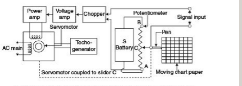
The position of the sliding contact, which corresponds to the input signal, is then used to drive a pen or stylus to create a trace on the moving chart paper.
Ultraviolet Recorder: Designed for recording high-frequency signals (up to several kHz), this recorder utilizes a series of moving coils mounted within a single magnet block.
Working Principle:
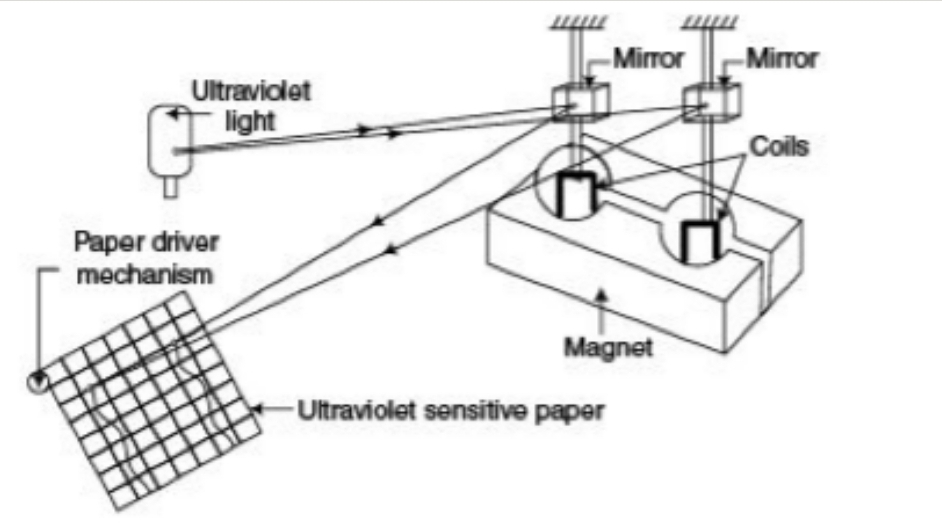
A silvered mirror attached to each coil reflects an ultraviolet light beam.
The deflection of the coil, due to the input signal, causes the reflected light beam to move accordingly.
The moving light beam creates a trace on ultraviolet-sensitive paper, providing a record of the signal’s variations.
Note: The ultraviolet-sensitive paper requires chemical treatment before storage.
Inkjet Recorder: This advanced recorder employs a fine jet of ink that is deflected according to the input signal to create a trace on the paper.
Working Mechanism:
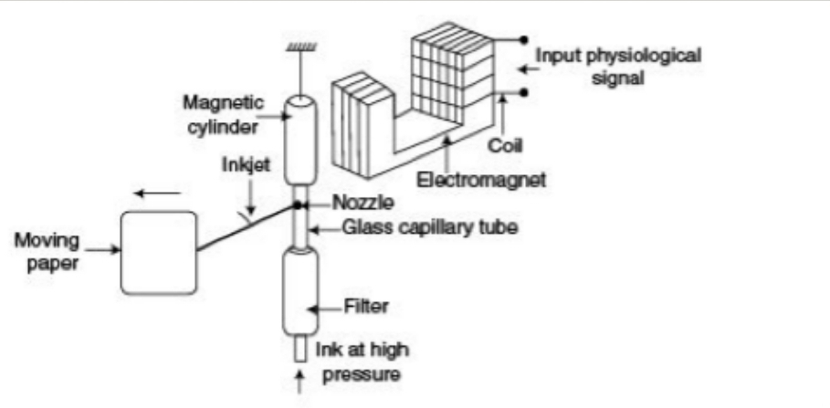
A capillary tube containing ink is placed within an electromagnetic field.
The varying magnetic field, generated by the input signal, interacts with a small magnet attached to the capillary tube, causing it to deflect.
This deflection directs the ink jet to trace the waveform on the paper.
Multichannel recording can be achieved using multiple capillaries of different colors.
Electrostatic Recorder: This sophisticated recorder utilizes an array of wire elements and charged ink particles to create a high-resolution image on paper.
Working Principle:
An imaging head applies a negative charge to selected wire elements while simultaneously applying a positive charge to adjacent electrodes.
Positively charged ink particles adhere to the negatively charged areas on the paper.
A vacuum knife removes excess toner, leaving behind a clear and permanent image.
Conclusion:
Biomedical recorders play an indispensable role in the acquisition and analysis of physiological data. By understanding the principles and characteristics of these diverse recording techniques, researchers and clinicians can select the most appropriate recorder for their specific needs, ensuring accurate and reliable data collection for a wide range of biomedical applications.
Things related