
A series circuit connects components along a single path. The same current flows through every component, while the source voltage is shared among them. Understanding how that voltage is divided makes it easier to analyze resistor circuits, voltage dividers, and batteries connected in series.
What is voltage?
Voltage is the difference in electric potential between two points. A battery provides energy to charges in a circuit, creating a potential difference between its terminals. As current flows through components, energy is transferred—for example, as heat, light, or motion—and the voltage changes across those components.
Voltage is measured between two points. A statement such as “this point is 5 V” usually means 5 V relative to a chosen reference point, often ground.
How voltage behaves in a series circuit
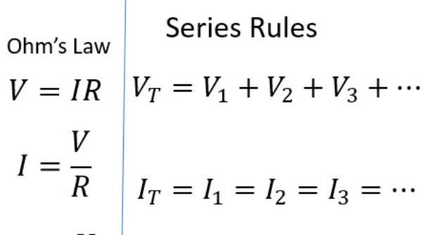
In a simple series circuit, each component is connected end to end, so there is only one path for current. Kirchhoff’s Voltage Law says that the voltage rises and drops around a complete loop balance out. For a source and series resistors:
Vsource = V₁ + V₂ + ⋯ + Vₙ
Each resistor’s voltage drop follows Ohm’s law:
Vₙ = I × Rₙ
Because the current is the same through every resistor, a larger resistance gets a larger share of the total voltage. (OpenStax: Resistors in Series and Parallel)
Example: Three resistors on a 9 V supply
Suppose a 9 V source powers three series resistors: 2 kΩ, 4 kΩ, and 3 kΩ.
First, find the total resistance:
Rtotal = 2 kΩ + 4 kΩ + 3 kΩ = 9 kΩ
Then calculate the circuit current:
I = V / Rtotal = 9 V / 9 kΩ = 1 mA
Now calculate each voltage drop:
- Across 2 kΩ: V₁ = 1 mA × 2 kΩ = 2 V
- Across 4 kΩ: V₂ = 1 mA × 4 kΩ = 4 V
- Across 3 kΩ: V₃ = 1 mA × 3 kΩ = 3 V
The drops add to 2 V + 4 V + 3 V = 9 V, matching the source.
Voltage at different points in the circuit
If the negative terminal of the 9 V source is chosen as 0 V, the positive terminal is at 9 V. Moving through the resistors in the direction of current, the potential falls by 2 V, then 4 V, then 3 V:
9 V → 7 V → 3 V → 0 V
Ideal connecting wires have no voltage drop. Real wires have small resistance, so their voltage drop is usually negligible in basic circuit examples but can matter in long wires or high-current systems.
Adding voltage sources in series
Voltage sources connected in series combine according to their polarity.
- If their polarities support each other, their voltages add. Two 1.5 V cells in series provide about 3 V.
- If one source is reversed, its voltage subtracts from the other. A 9 V source in series with an opposing 3 V source gives a net 6 V.
For AC sources at the same frequency, add their voltages with both magnitude and phase taken into account. If their frequencies differ, their instantaneous voltages still add, but the result is a combined waveform rather than one sinusoid with a single frequency. (OpenStax: AC Sources)
When connecting real batteries in series, use compatible battery types and follow the manufacturer’s instructions. A damaged or incorrectly connected battery can create a short circuit or other hazard.
Common uses of series voltage
- Voltage dividers: Two or more resistors in series provide a lower voltage at their junction. The output can change when the connected load draws current, so divider values must be chosen for the circuit.
- Battery packs: Cells are connected in series to increase the pack’s voltage.
- Decorative lights and simple circuits: Some designs connect lamps or other components in series, though one failed component may interrupt current through the entire string.
- Voltage measurement: A voltmeter measures the potential difference between two points, such as across one resistor in a series circuit.
Key points
In a series circuit, the current is the same through each component, and the source voltage is divided among them. For resistors, use V = IR to find each drop; the drops around the loop add to the source voltage. Voltage sources in series add or subtract according to polarity, and AC sources also require attention to phase and frequency.