
A material’s resistance can change as its temperature changes. In many metals, resistance rises as temperature increases. Some semiconductor components, such as NTC thermistors, behave in the opposite way.
This temperature dependence matters when designing circuits, measuring temperature, and testing electrical machine windings.
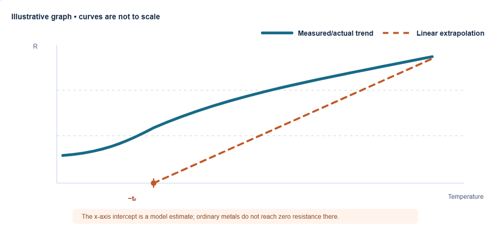
How temperature affects resistance
As a metal heats, its atoms vibrate more. Electrons moving through the material experience more scattering, so resistance generally increases.
The trend differs by material. An NTC thermistor is designed so its resistance decreases as temperature rises. Avoid assuming that all nonmetals behave the same way: resistance-temperature behavior depends on the material and its construction.
Estimating resistance at a new temperature
For many metals over a limited temperature range, resistance can be estimated using this linear approximation:
R₂ = R₁ × [1 + α₁(T₂ − T₁)]
Where:
- R₁ is resistance at the reference temperature T₁
- R₂ is resistance at the new temperature T₂
- α₁ is the temperature coefficient referenced to T₁
The approximation becomes less reliable over a wide temperature range or for materials with nonlinear behavior. For those cases, use the manufacturer’s data or a resistance-temperature curve. (OpenStax: Resistance and Resistivity)
The “inferred zero-resistance temperature”
If a straight-line resistance model for a metal is extended backward, it may cross the temperature axis below 0°C. This intercept is sometimes called the inferred zero-resistance temperature.
It is a mathematical result of extending a simplified model beyond its useful range. It does not mean an ordinary metal reaches zero resistance at that temperature. Superconductivity, which occurs in certain materials below a critical temperature, is a separate physical effect.
Estimating transformer winding temperature
A transformer’s winding resistance can be measured before and after a temperature-rise test. The change in resistance can be used to estimate the winding’s average temperature, even when the winding itself cannot be accessed for a direct temperature measurement.
For a copper winding, a common resistance-method calculation is:
T₂ = (R₂ / R₁) × (K + T₁) − K
Where K is approximately 234.5°C for copper. For aluminum windings, a commonly used value is 225°C. The applicable test standard and conductor material determine the values and procedure to use. (IEC 60076-2: Transformer temperature-rise tests)
For example, a copper winding measures 10 Ω at 20°C and 12 Ω after a test:
T₂ = (12 / 10) × (234.5 + 20) − 234.5 ≈ 70.9°C
If the ambient temperature at the end of the test is 25°C, the estimated average winding temperature rise is about 45.9°C. This method estimates average winding temperature, not the hottest spot inside the winding. Measurement timing and the test procedure affect the result.
Key points
Metal resistance usually rises with temperature, while particular components such as NTC thermistors are designed to show decreasing resistance. A linear formula is useful for estimates over a limited temperature range. Transformer winding resistance can also help estimate average winding temperature when measured and calculated using the applicable test procedure.