
A shunt resistor is a low-value resistor used to measure or redirect current. In current-measurement circuits, the current flowing through the shunt creates a small voltage drop. Measure that voltage, and you can calculate the current using Ohm’s law.
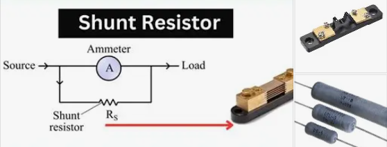
Shunts are common in ammeters, power supplies, battery monitors, and motor controls. Because the resistance is often very small, details like heat, connection layout, and measurement accuracy matter.
How does a shunt resistor work?
For current measurement, the shunt is usually connected in series with the load. The current flowing through the circuit also flows through the shunt, producing a voltage across it:
V = I × R
Rearranged to find current:
I = V / R
For example, a 1 mΩ shunt carrying 10 A produces:
V = 10 A × 0.001 Ω = 0.01 V, or 10 mV
A voltmeter or current-sense amplifier measures this small voltage and converts it to a current reading. This is the common modern use of “shunt resistor.” (Tektronix: Measuring Current Using Shunt Resistors)
Shunts inside ammeters
In a traditional analog ammeter, a shunt resistor is connected in parallel with the meter movement. Most of the current passes through the shunt, while a small, known portion passes through the sensitive meter movement. This lets the instrument measure currents greater than the movement could handle by itself.
Digital multimeters also use internal shunt resistors on their current ranges, though the circuit design differs. When measuring current with a multimeter, follow the meter’s instructions: the leads usually need to go into a dedicated current jack, and the meter must be connected in series with the circuit.
How to size a shunt resistor
Choose the resistance based on the maximum current and the voltage drop you can allow:
R = Vshunt / Imax
Suppose a shunt should produce 50 mV at 100 A:
R = 0.050 V / 100 A = 0.0005 Ω = 0.5 mΩ
Then check its power dissipation:
P = I² × R
For the same example:
P = 100² × 0.0005 = 5 W
The shunt must be rated to handle this heat under the real operating conditions, with suitable margin for continuous current, ambient temperature, airflow, and overloads. A shunt that is too large creates more voltage drop and heat; one that is too small produces a harder-to-measure signal.
Also consider accuracy requirements. Resistance tolerance and temperature change affect the current reading. For low-resistance, high-current measurements, a four-terminal shunt with separate current and voltage connections can reduce errors from terminals and circuit traces. This is known as a Kelvin connection. (Analog Devices: Kelvin connections for shunt measurement)
How to measure current with a shunt
- Put the shunt in series with the circuit current you want to measure.
- Measure the voltage directly across the shunt’s sense terminals.
- Divide the measured voltage by the shunt resistance: I = V / R.
- Check that the shunt, meter, and wiring are rated for the current and heat involved.
At very low resistance values, ordinary wire, solder joints, and contact resistance can distort the result. Use the shunt’s specified sense points or Kelvin connections when accuracy matters.
Can you build a shunt resistor from wire?
In principle, a length of wire has resistance, and its resistance depends on its material, length, cross-sectional area, and temperature. In practice, a wire-made shunt can be difficult to measure accurately. The wire’s connections, temperature rise, and variations in material or dimensions all affect its resistance.
For precise or high-current measurements, use a purpose-built current shunt with a known resistance and current rating. For a classroom demonstration or noncritical experiment, wire may illustrate the principle, but it should not be treated as a calibrated measurement component.
Common applications
Shunt resistors are used in:
- Current measurement: An ammeter or monitoring circuit measures the voltage across a known shunt.
- Battery and power monitoring: A current-sense circuit tracks charging or discharging current.
- Motor and power-control circuits: A controller measures current to regulate operation or detect overloads.
- Analog ammeters: A parallel shunt carries most of the current around a sensitive meter movement.
A shunt used to measure current is not generally an “overvoltage protector.” Protection circuits may use current-sense shunts to detect a fault and trigger a separate device, such as a fuse, switch, or controller. A shunt also does not automatically bypass a failed component; that requires a circuit designed for that purpose.
Key points
A current-measuring shunt creates a small, measurable voltage that is proportional to current. Use R = V/I to select its resistance and P = I²R to check its heating. For accurate readings at low resistance, choose a rated shunt and connect its sense leads carefully.