
A pull-down resistor connects a signal line to ground so that the line reads as logic LOW when nothing else is driving it. It prevents a digital input from floating at an unpredictable voltage.
Pull-down resistors are commonly used with switches, microcontroller inputs, and control signals. The right value depends on the circuit’s voltage levels, input characteristics, and how much current you can allow when the signal is HIGH.
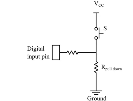
Why a digital input needs a defined state
A digital input is designed to recognize a LOW or HIGH voltage. If a switch or output driver is disconnected, the input may be left electrically floating. Noise or small leakage currents can then make its voltage drift, causing unreliable readings or unexpected behavior.
A pull-down resistor provides a weak path to ground. That gives the input a default LOW state when no other source is connected. (Microchip: GPIO and floating inputs)
How a pull-down resistor works
A common switch circuit connects the input pin to ground through a resistor and to the supply voltage through a switch:
- Switch open: The resistor pulls the input toward ground, so it reads LOW.
- Switch closed: The switch connects the input to the supply voltage, so it reads HIGH. Current flows through the resistor to ground.
The resistor limits the current when the switch is closed. Without it, the switch could connect the supply directly to ground.
The actual HIGH and LOW thresholds vary by device. Check the microcontroller or logic chip’s datasheet rather than assuming particular voltage ranges.
Pull-down vs. pull-up resistors
| Resistor | Connected between | Default input state |
|---|---|---|
| Pull-down | Signal and ground | LOW |
| Pull-up | Signal and supply voltage | HIGH |
Both resistors give an input a defined state when no active signal is driving it. Which one to use depends on the circuit and the behavior you want by default.
How to choose a pull-down resistor value
There is no single correct value for every circuit. Choose a value that:
- Keeps the input voltage below the device’s maximum LOW threshold when the switch is open.
- Allows enough current through the resistor when the switch is closed.
- Does not waste too much power or place too much load on the signal source.
- Works with the input’s leakage current and any noise or wiring conditions.
For a simple switch-to-supply circuit, the current through the resistor when the switch is closed is approximately:
I = Vcc / R
For example, with a 3.3 V supply and a 10 kΩ resistor:
I = 3.3 V / 10,000 Ω = 0.33 mA
That is a common starting point for many basic logic inputs, but it is not a universal recommendation. A higher resistance uses less current but makes the input more vulnerable to leakage and noise. A lower resistance holds the input more firmly but draws more current when the switch is closed.
For a design that must meet guaranteed voltage limits, use the device’s datasheet values for input thresholds and leakage current. Texas Instruments explains how leakage and logic thresholds affect pull-resistor selection. (TI: Choosing an appropriate pull-up/pull-down resistor)
Internal and external pull-down resistors
Many microcontrollers offer programmable internal pull-up or pull-down resistors. These can reduce the number of external components in a simple circuit. Their resistance is often relatively high and may vary across devices, so check the datasheet to see whether an internal resistor is suitable for your circuit.
An external resistor can provide a more controlled value or a stronger pull when the signal is exposed to noise, has long wiring, or must meet specific timing or voltage requirements.
Common applications
Pull-down resistors are used to:
- Give a microcontroller input a default LOW state.
- Set the default state of a switch or button input.
- Keep control pins, such as enable or reset signals, at a known level when a driver is disconnected.
- Prevent unused digital inputs from floating, where the device manufacturer recommends doing so.
I²C bus lines typically use pull-up resistors because the bus uses open-drain or open-collector signaling. A pull-down resistor is not the standard way to set I²C’s idle state. (NXP: I²C-bus specification and user manual)
Common mistakes
- Assuming every chip uses the same logic thresholds: Check the datasheet for the specific device and supply voltage.
- Choosing a very high resistance without checking leakage: Input leakage can shift the signal voltage enough to cause an unreliable LOW.
- Choosing a very low resistance: This can waste power and load the signal source when the line is driven HIGH.
- Adding a pull-down where the interface needs a pull-up: Some interfaces, including standard I²C buses, rely on pull-ups.
Key points
A pull-down resistor gives a signal a default LOW state when no active source is driving it. It connects the input to ground while allowing another circuit, such as a switch, to drive the input HIGH. Select its value using the device’s datasheet, supply voltage, input thresholds, leakage, and acceptable current.