
Electrical resistance describes how much a component or material opposes electric current. It is measured in ohms, represented by Ω. A resistor’s circuit symbol is usually a zigzag line in many US schematics or a rectangle in IEC-style diagrams.
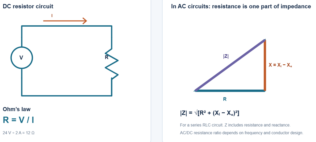
What is resistance?
When voltage is applied across a component, it drives current through it. For an ohmic component under stated conditions, resistance is the ratio of voltage to current:
R = V / I
A resistance of 1 Ω means a voltage of 1 V across the component produces a current of 1 A.
Resistance also depends on a conductor’s material and dimensions:
R = ρ × L / A
Where ρ is resistivity, L is length, and A is cross-sectional area. A longer conductor has more resistance; a thicker conductor has less. Temperature can also change resistance. (OpenStax: Resistance and Resistivity)
Ohm’s law example
A 24 V supply drives 2 A through an unknown resistor. Its resistance is:
R = V / I = 24 V / 2 A = 12 Ω
This calculation assumes the component behaves ohmically at that operating point. Some components, such as diodes and lamps, do not have a constant resistance as voltage, current, or temperature changes.
Resistance and power formulas
For a resistor, power can be written in three equivalent ways:
P = V × I
P = I² × R
P = V² / R
For example, if a 48 W load operates at 24 V, its effective resistance at that operating condition is:
R = V² / P = 24² / 48 = 12 Ω
A filament lamp’s resistance changes significantly as it heats, so this calculated value describes the operating condition and may differ from its resistance when cold.
For a constant current through a fixed resistance, the heat energy produced over time is:
E = I² × R × t
This is the heating effect used in devices such as electric heaters, kettles, and toasters. (OpenStax: Electrical Energy and Power)
Resistance in DC and AC circuits
DC resistance
For a conductor carrying steady DC, resistance can usually be calculated from its material, length, cross-sectional area, and temperature. Components such as inductors and capacitors also affect how a DC circuit behaves during switching or startup; in ideal steady state, an inductor acts like a short circuit and a capacitor like an open circuit.
AC resistance and impedance
In AC circuits, resistance and impedance are related but different:
- Resistance (R) dissipates energy, usually as heat.
- Reactance (X) comes from inductors and capacitors and varies with frequency.
- Impedance (Z) combines resistance and reactance.
For a series RLC circuit:
Z = R + j(XL − XC)
The magnitude is:
|Z| = √[R² + (XL − XC)²]
For a pure resistor, impedance is simply its resistance. For circuits with inductors or capacitors, total impedance also includes reactance. (OpenStax: RLC Series AC Circuits)
A conductor can also have a higher effective AC resistance than its DC resistance. At higher frequencies, skin effect pushes more current toward the conductor’s surface, reducing the effective area carrying current. Proximity to other conductors can add further losses. The AC/DC resistance ratio depends on frequency, conductor size, material, and arrangement; there is no universal ratio such as 1.6. (IEEE: Skin effect)
How temperature affects resistance
Many metals, including copper and aluminum, have higher resistance at higher temperatures over ordinary operating ranges. Some semiconductor components, such as NTC thermistors, have lower resistance as they heat. The behavior depends on the material and component, so use its specified resistance-temperature data when accuracy matters.
Key points
Resistance is measured in ohms and relates voltage to current through R = V/I for an ohmic component. A conductor’s length, area, material, and temperature affect its resistance. In AC circuits, impedance includes resistance and reactance; the effective AC resistance of a conductor can also rise with frequency, but the amount depends on the design and operating conditions.