What is an Oscillator?
The oscillator is a mechanical or electronic device and the working principle of the oscillator is, the periodic change between the two things depends on the changes in the energy. The oscillations are used in radios, watches, metal detectors, and in many other devices.
The oscillator converts the DC (direct current) from the power supply to an AC (alternating current), used in many electronic devices. The signal used in the oscillator is a sine wave & the square wave. The best examples of an oscillator are, the signals are broadcasted by the television transmitter and radio, CLKs which are used in the computers and also in the video games.
The oscillator works on the principle of oscillation and it is a mechanical or electronic device. The periodic variation between the two things is based on the changes in energy. The oscillations are used in watches, radios, metal detectors, and many other devices that use the oscillators.
Principle of Oscillators
The oscillator converts the direct current from the power supply to an alternating current and they are used in many electronic devices. The signals used in the oscillators are a sine wave and the square wave. Some of the examples are the signals are broadcasted by the radio and television transmitter, clocks which are used in computers and in video games.
Types of Oscillator Circuits
There are two types of oscillator circuits available they are linear and nonlinear oscillators. The linear oscillators give the sinusoidal input. The linear oscillators consist of a mass m and its force in the linear equilibrium. By applying the hook’s low the spring creates the force that i9s in linear for small displacements.
The different types of oscillator circuits are mentioned below and some of them are explained.
- Armstrong Oscillator
- Crystal Oscillator
- Hartley oscillator
- RC Phase Shift Oscillator
- Colpitts Oscillators
- Cross-Coupled Oscillator
- Relaxation oscillator
- Meissner Oscillator
- Phase shift oscillator
- Phase Shift Oscillator
- Wine Bridge Oscillator
- Sawtooth Voltage-Controlled Oscillator (VCO)
- The Wien-Bridge Oscillator:One type of sinusoidal feedback oscillator is the Wien-bridge oscillator. A fundamental part of the Wien-bridge oscillator is a lead-lag circuit like that and C1 together form the lag portion of the circuit; R2 and C2 form the lead portion. The operation of this lead-lag circuit is as follows. At lower frequencies, the lead circuit dominates due to the high reactance of C 2 . As the frequency increases, X C2 decreases, thus allowing the output voltage to increase. At some specified frequency, the response of the lag circuit takes over, and the decreasing value of XCI causes the output voltage to decrease. The response curve for the lead-lag circuit shown in Figure 10.1(b) indicates that the output voltage peaks at a frequency called the resonant frequency,!,. At this point. the attenuation (Vout/Vin) of the circuit is 1/3 if R1 = R2 and XC1 = X C2 as stated by the following equation
A Wien bridge oscillator is a type of electronic oscillator that generates sine waves. It can generate a large range of frequencies. The oscillator is based on a bridge circuit originally developed by Max Wien in 1891 for the measurement of impedances. The bridge comprises four resistors and two capacitors.The oscillator can also be viewed as a positive gain amplifier combined with a band pass filter that provides positive feedback. Automatic gain control, intentional non-linearity and incidental non-linearity limit the output amplitude in various implementations of the oscillator.
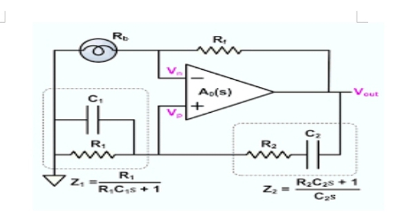
To summarize, the lead-lag circuit in the Wien-bridge oscillator has a resonant frequency, at which the phase shift through the circuit is 0 0 and the attenuation is 1/3. Below, the lead circuit dominates and the output leads the input. Above fr, the lag circuit dominates and the output lags the input. The Basic Circuit The lead-lag circuit is used in the positive feedback loop of an op-amp, as shown below A voltage divider is used in the negative feedback loop.
Wien-bridge oscillator circuit can be viewed as a non-inverting amplifier configuration with the input signal fed back from the output through the lead-lag circuit. Recall that the closed-loop gain of the amplifier is determined by the voltage divider.
2. The Phase-Shift Oscillator
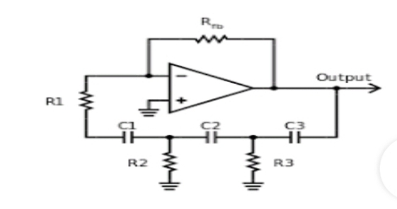
Figure 11.1 shows a sinusoidal feedback oscillator called the phase-shift oscillator. Each of the three RC circuits in the feedback loop can provide a maximum phase shift approaching 90°. Oscillation occurs at the frequency where the total phase shift through the three RC circuits is 180°. The inversion of the op-amp itself provides the additional 180° to meet the requirement for oscillation of a 360° (or 0°) phase shift around the feedback loop.
Phase-shift oscillator
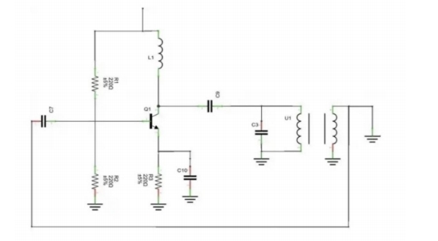
3. The Colpitts Oscillator:
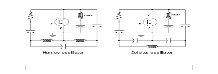
One basic type of resonant circuit feedback oscillator is the Colpitts, named after its inventor-as are most of the others we cover here. As shown in Figure 11.4, this type of oscillator uses an LC circuit in the feedback loop to provide the necessary phase shift and to act as a resonant filter that passes only the desired frequency of oscillation.
A crystal oscillator is an electronic oscillator circuit that is used for the mechanical resonance of a vibrating crystal of piezoelectric material. It will create an electrical signal with a given frequency. This frequency is commonly used to keep track of time for example wristwatches are used in digital integrated circuits to provide a stable clock signal and also used to stabilize frequencies for radio transmitters and receivers.
Loading Effects on the Frequency of Oscillation As indicated in Figure 12.1, the input impedance of the amplifier acts as a load on the resonant feedback circuit and reduces the Q of the circuit. Recall from your study of resonance that the resonant frequency of a parallel resonant circuit depends on the Q, according to the following formula:
As a rule of thumb, for a Q greater than 10, the frequency is approximately TLC 21 ,as stated in Equation 16-5. When Q is less than 10, however, fr, is reduced significantly.
Figure 12.1 Zin of the amplifier loads the feedback circuit
A FET can be used in place of a BJT, as shown in Figure 12.2, to minimize the loading effect of the transistor’s input impedance. Recall that FETs have much higher input impedances than do bipolar junction transistors. Also, when an external load is connected to the oscillator output, as shown in Figure l2.3(a),fr, may decrease, again because of a reduction in Q. This happens if the load resistance is too small. In some cases, one way to eliminate the effects of a load resistance is by transformer coupling.
4. The Hartley Oscillator
The Hartley oscillator is similar to the Colpitts except that the feedback circuit consists of two series inductors and a parallel capacitor as shown below
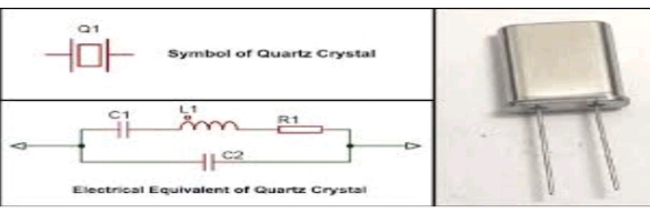
5. The quart crystal Oscillators:
The most stable and accurate type of feedback oscillator uses a piezoelectric crystal in the feedback loop to control the frequency. 3.9.1The Piezoelectric Effect Quartz is one type of crystalline substance found in nature that exhibits a property called the piezoelectric effect. When a changing mechanical stress is applied across the crystal to cause it to vibrate, a voltage develops at the frequency of mechanical vibration. Conversely, when an ac voltage is applied across the crystal, it vibrates at the frequency of the applied voltage. The greatest vibration occurs at the crystal’s natural resonant frequency, which is determined by the physical dimensions and by the way the crystal is cut. Crystals used in electronic applications typically consist of a quartz wafer mounted between two electrodes and enclosed in a protective “can” as shown in Figure 13.2(a) and (b). A schematic symbol for a crystal is shown in Figure 13.2(c), and an equivalent RLC circuit for the crystal appears in Figure 13.2(d). As you can see, the crystal’s equivalent circuit is a series-parallel RLC circuit and can operate in either series resonance or parallel resonance. At the series resonant frequency, the inductive reactance is cancelled by the reactance of Cs. The remaining series resistor, Rs, determines the impedance of the crystal. Parallel resonance occurs when the inductive reactance and the reactance of the parallel capacitance, Cm are equal. The parallel resonant frequency is usually at least I kHz higher than the series resonant frequency.
A quartz crystal
6. Crystal oscillator:
A great advantage of the crystal is that it exhibits a very high Q (Qs with values of several thousand are typical). An oscillator that uses a crystal as a series resonant tank circuit is shown in Figure 13.3(a). The impedance of the crystal is minimum at the series resonant frequency, thus providing maximum feedback. The crystal tuning capacitor, Cc, is used to “fine tune” the oscillator frequency by “pulling” the resonant frequency of the crystal slightly up or down.
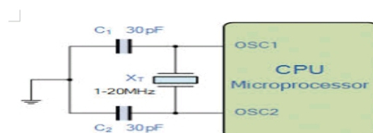
A modified Colpitts configuration is shown in Figure 13.3(b) with a crystal acting as a parallel resonant tank circuit. The impedance of the crystal is maximum at parallel resonance, thus developing the maximum voltage across the capacitors. The voltage across C1 is fed back to the input.
Modes of oscillation in the Crystal Piezoelectric crystals can oscillate in either of two modes-fundamental or overtone. The fundamental frequency of a crystal is the lowest frequency at which it is naturally resonant. The fundamental frequency depend on the crystal’s mechanical dimensions, type of cut, and other factors, and is inversely proportional to the thickness of the crystal slab. Because a slab of crystal cannot be cut too thin without fracturing, there is an upper limit on the fundamental frequency. For most crystals, this upper limit is less than 20 MHz. For higher frequencies, the crystal must be operated in the overtone mode. Overtones are approximate integer multiples of the fundamental frequency. The overtone frequencies are usually, but not always, odd multiples (3, 5, 7, . . . ) of the fundamental.
7. Relaxation oscillator:
The second major category of oscillators is the relaxation oscillator. Relaxation oscillators use an RC timing circuit and a device that changes state to generate a periodic waveform. In this section, you will learn about several circuits that are used to produce non sinusoidal waveforms.
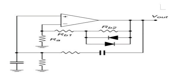
8. A Sawtooth Voltage-Controlled Oscillator (VCO)
The voltage-controlled oscillator (VCO) is a relaxation oscillator whose frequency can be changed by a variable dc control voltage. VCOs can be either sinusoidal or non sinusoidal. One way to build a sawtooth VCO is with an op-amp integrator that uses a switching device (PUT) in parallel with the feedback capacitor to terminate each ramp at a prescribed level and effectively “reset” the circuit. Figure 16-31(a) shows the implementation. As you learned in Chapter 1 I, the PUT is a programmable unijunction transistor with an anode, a cathode, and a gate terminal. The gate is always biased positively with respect to the cathode. When the anode voltage exceeds the gate voltage by approximately 0.7 V, the PUT turns on and acts as a forward-biased diode. When the anode voltage falls below this level, the PUT turns off. Also, the current must be above the holding value to maintain conduction. The operation of the sawtooth VCO begins when the negative dc input voltage, – V IN , produces a positive-going ramp on the output. During the time that the ramp is increasing, the circuit acts as a regular integrator. The PUT triggers on when the output ramp (at the anode) exceeds the gate voltage by 0.7 V The gate is set to the approximate desired sawtooth peak voltage. When the PUT turns on, the capacitor rapidly discharges, as shown in Figure l6-31(b). The capacitor does not discharge completely to zero because of the PUT’s forward voltage. V F . Discharge continues until the PUT current falls below the holding value. At this point, the PUT turns off and the capacitor begins to charge again, thus generating a new output ramp. The cycle continually repeats, and the resulting output is a repetitive sawtooth waveform, as shown. The sawtooth amplitude and period can be adjusted by varying the PUT gate voltage.
The frequency of oscillation is determined by the RiC time constant of the integrator and the peak voltage set by the PUT. Recall that the charging rate of a capacitor is VIN/RiC. The time it takes a capacitor to charge from V F to V p is the period, T, of the sawtooth waveform (neglecting the rapid discharge time).
After completing this section, you should be able to · Describe and analyze the basic operation of relaxation oscillators. Discuss the operation of basic triangular-wave oscillators . Discuss the operation of a voltage-controlled oscillator (VCO) . Discuss the operation of a square-wave relaxation oscillator
9. The Armstrong oscillator
The Armstrong oscillator is an LC electronic oscillator and to generate this oscillator we are using the inductor and the capacitor. In 9012 the US engineer Edwin Armstrong has invented the Armstrong oscillator and it was the first oscillator circuit and also in1913 this oscillator was used in the first vacuum tube by the Alexander Meissner who as an Austrian engineer.
The Armstrong oscillator is known as the tickler oscillator because of the individual features of the feedback signal should produce the oscillations are magnetically coupled to the tank indicator. The Armstrong oscillator is also called as the meissner oscillator or tickler oscillator.
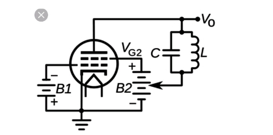
10. The dynatron oscillator
The dynatron oscillator, invented in 1918 by Albert Hull at General Electric, is an obsolete vacuum tube electronic oscillator circuit which uses a negative resistance characteristic in electrode vacuum tubes, caused by a process called secondary emission. It was the first negative resistance vacuum tube oscillator. The dynatron oscillator circuit was used to a limited extent as beat frequency oscillators (BFOs), and local oscillators in vacuum tube radio receivers as well as in scientific and test equipment from the 1920s to the 1940s but became obsolete around World war 2 due to the variability of secondary emission in tubes.