
What is signal
Signals is a physical quantity or an electrical waveform that carries information. It can also be define as a pattern, or changes that convey information from a source to a destination. The purpose of a signal is to transmit this information timely and accurately. Signal is a physical and electrical representation of information that is used to transmit data in various communication system.
Type of electrical signal
- Analog signals: They are continuous waveforms that vary in time and amplitude
- Digital signals: They are not continuous wave but are discrete in nature i.e their values are typically binary digits (bit) a “0” and a “1”
list and explain the two types signal transmission as it relates to digital communication
What is a digital signal?
digital signal is a signal that represents data as a sequence of discrete values. A digital signal can only take on one value from a finite set of possible values at a given time. There are a wide range of devices that use digital signals. These include devices such as smart phones, smart watches, and digital clocks.
What is analog signals?
Analog signals is the output of light/sound wave converted to electrical energy. Analog signals are used in a wide-range of technologies, including analog clocks, landline phones, and rotary volume knobs on a radio.
What is the difference between analog and digital signals?
Analog signals are a type of signal sent in a continuous wave. These waves can vary in both amplitude and frequency. Digital signals are signals that are represented in discrete values. This means there is a finite amount of values that the signal can be converted into.
A neat and label block diagram of elements of digital communication system
Explain briefly each of the block vividly
understanding.
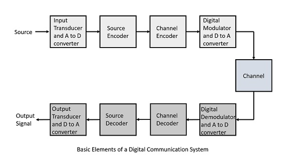
Following are the sections of the digital communication system.
Source
The source can be an analog signal. Example: A Sound signal
Input Transducer
This is a transducer which takes a physical input and converts it to an electrical signal (Example: microphone). This block also consists of an analog to digital converter where a digital signal is needed for further processes.
A digital signal is generally represented by a binary sequence.
Source Encoder
The source encoder compresses the data into minimum number of bits. This process helps in effective utilization of the bandwidth. It removes the redundant bits unnecessaryexcessbits,i.e.,zeroes.
Channel Encoder
The channel encoder, does the coding for error correction. During the transmission of the signal, due to the noise in the channel, the signal may get altered and hence to avoid this, the channel encoder adds some redundant bits to the transmitted data. These are the error correcting bits.
Digital Modulator
The signal to be transmitted is modulated here by a carrier. The signal is also converted to analog from the digital sequence, in order to make it travel through the channel or medium.
Channel
The channel or a medium, allows the analog signal to transmit from the transmitter end to the receiver end.
Digital Demodulator
This is the first step at the receiver end. The received signal is demodulated as well as converted again from analog to digital. The signal gets reconstructed here.
Channel Decoder
The channel decoder, after detecting the sequence, does some error corrections. The distortions which might occur during the transmission, are corrected by adding some redundant bits. This addition of bits helps in the complete recovery of the original signal.
Source Decoder
The resultant signal is once again digitized by sampling and quantizing so that the pure digital output is obtained without the loss of information. The source decoder recreates the source output.
Output Transducer
This is the last block which converts the signal into the original physical form, which was at the input of the transmitter. It converts the electrical signal into physical output (Example: loud speaker).
Output Signal
This is the output which is produced after the whole process. Example − The sound signal received.
Characteristics/properties of signals
- Amplitude: These refers to the magnitude or strength of the signals
- Frequency: is the number of cycles or oscillation that occurs within a given time period. Measured in hertz (Hz)
- Phase: Refers to the relative positioning or timing of a signal waveform with respect to a reference
- Duration: Represent the length of time that a signal persist or exist.
- Periodicity: Refers to whether a signal exhibits a repetitive pattern or not.
- Symmetry: These describe the balance or distribution of a signal waveform
- Bandwidth: it refers to the range of frequency that signal occupies or occupies for transmission
- Energy and power: are measures of the total or average amount of signal energy overtime. Energy is related to the finite duration of a signal while power is the energy per unit time
Example of analog signals
- Audio signal: In electronics, an audio signal generator is a piece of electronic test equipment that generates electrical signals in the audio frequency range. These signals are usually created using a voltage-controlled oscillator or a pulse train and then route to an amplifier before being sent to the loudspeakers, whose output makes up the desired sound.
- Electromagnetic waves: The electromagnetic waves consist of both electric and magnetic fields. Electromagnetic waves can travel long distances in space. The electromagnetic signals are also called radio frequency (RF) waves
- Voltage signal: a voltage signal refers to an electrical signal that varies in voltage, typically measured in volts. Voltage signals are often used to represent analog data such as sound, temperature, and light intensity
Application of analog signals ( where we can find it)
- Analog telephone
- AM/FM radio
- Television broadcasting
Note: that analog signals are susceptible (likely or affected) to noise and distortion during transmission, which can degrade the quantity of the received signal.
Advantages of digital signals
- Immunity to noise ( insusceptible)
- Better signal quantity
- Efficient use of bandwidth
Digital Modulation
It is the whole process of modifying a digital signal to enable it to be transmitted over a communication channel.
Digital modulation techniques
- Amplitude shift keying (ASK): In ASK the amplitude of the common signal varied to represent digital “1s” and “0s“
- Frequency shift keying (FSK): It involves shifting the frequency of the carrier signal between two or more predefine frequencies to represent different digital symbols. For example, if we have two sine waves with different frequencies but equal amplitudes, they would be indistinguishable on an oscilloscope unless we normalized their amplitudes first. If you multiply each frequency by its corresponding normalized amplitude measurement, you can use frequency as an independent variable.
- Phase shift keying (PSK): It changes the phase of the carrier signals to represents digital symbols ( 00, 900, 1800, 2900 )
- Quadrature amplitude modulation (QAM): Is a complex modulation scheme that combines amplitude and phase modulation. (QAM represents digital data in varying both the amplitude and phase of the carrier)
- Quadrature phase shift keying (QPSK): is a modulation scheme that allows one symbol to transfer two bits of data. There are four possible two-bit numbers (00, 01, 10, 11), and consequently we need four phase offsets. Again, we want maximum separation between the phase options, which in this case is 90°
- Orthogonal frequency division multiplexing (OFDM): Orthogonal frequency division multiplexing (OFDM) takes a digital information signal with bit rate Rb, maps n-bit words on to M = 2n symbols (each symbol being a complex number representing the amplitude and phase of an M-ary modulation scheme), splits the resulting symbol stream (rate Rs = Rb/n) into N parallel streams (each with rate ROFDM = Rs/N) and modulates each stream onto one of N different carriers [12]. The N frequencies chosen for the carriers are such that the carriers are mutually orthogonal over one OFDM symbol period, TOFDM = 1/ROFDM, allowing independent recovery of each parallel information stream.
Digital modulation principle
- Pulse amplitude modulation (PAM): Converts a discrete time signal into a variable amplitude continuous time signal that is good for high-speed wired communication system.
- Pulse position modulation (PPM): Is a modulation method that only makes every pulse in the carrier pulse sequence change within time but without changing shape and amplitude of pulse signal.
- Pulse Code modulation (PCM): is a digital scheme for transmitting analog data. It converts an analog signal into digital form. Using PCM, it is possible to digitize all forms of analog data, including full-motion video, voice, music, telemetry, etc.
- Pulse Width modulation (PWM): is a modulation technique that generates variable-width pulses to represent the amplitude of an analog input signal. The output switching transistor is on more of the time for a high-amplitude signal and off more of the time for a low-amplitude signal.