
Key learnings
- A voltage source maintains a potential difference between its terminals and can supply electrical energy to a circuit.
- An independent voltage source has a specified voltage that does not depend on another circuit quantity. Its voltage may be constant or may vary with time.
- A dependent voltage source has a voltage controlled by another voltage or current in the circuit.
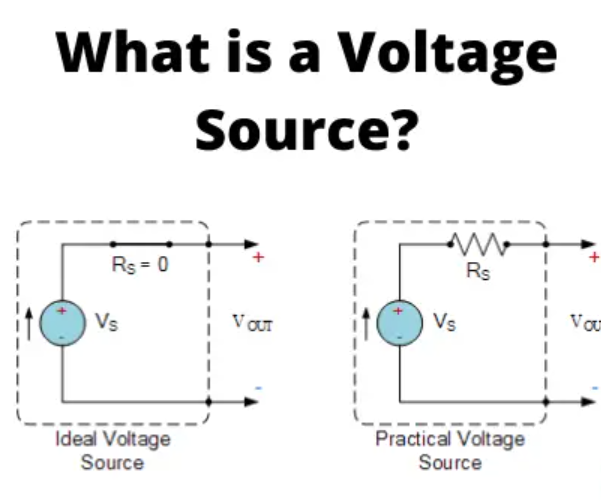
- An ideal voltage source has zero internal resistance in its model and maintains its specified voltage for any load current.
- A practical voltage source can be modeled as an ideal source in series with internal resistance. Its terminal voltage usually falls when it supplies current.
- “Voltage source” does not mean a device always supplies power: depending on the circuit, a source may absorb power too.
What is a voltage source?
A voltage source is a two-terminal circuit element that establishes a voltage between its terminals. When connected to a complete circuit, this potential difference can drive current through the circuit.
A battery, a laboratory power supply, and an alternator connected to a suitable circuit are examples of voltage sources. In circuit analysis, voltage sources are often shown as idealized symbols, even when the real device has internal resistance and other limitations.
Voltage is the difference in electric potential between two points. It can also be described as energy transferred per unit charge:
V = \frac{W}{Q}
Here, V is voltage in volts, W is energy in joules, and Q is electric charge in coulombs.
A water pump is sometimes used as an analogy: it creates a pressure difference that can drive water through a pipe. In an electrical circuit, a voltage source creates a potential difference that can drive charge through a closed path. The analogy is helpful, but voltage does not literally “push electrons” in the same way a pump pushes water.
Types of voltage sources
Voltage sources are commonly classified in two ways:
- Independent or dependent, based on whether the source’s voltage is set independently or controlled by another circuit quantity.
- DC or time-varying, based on how the source voltage changes with time.
These categories describe different things. For example, an independent source can provide either a constant DC voltage or a time-varying voltage.
| Source type | What determines its voltage? | Example |
|---|---|---|
| Independent voltage source | A specified value or waveform | Battery or signal generator |
| Voltage-controlled voltage source (VCVS) | A voltage elsewhere in the circuit | Amplifier model |
| Current-controlled voltage source (CCVS) | A current elsewhere in the circuit | Circuit model of a transresistance amplifier |
| Ideal voltage source | Its specified voltage, regardless of load current | Ideal circuit model |
| Practical voltage source | Its internal model and connected load | Real battery or power supply |
Independent voltage source
An independent voltage source provides a specified voltage that does not depend on another voltage or current elsewhere in the circuit. Its value may be constant, or it may follow a time-varying waveform specified by the problem or device.
In many circuit diagrams, an independent voltage source is represented by a circle. A DC source may be marked with + and −; an AC source may include a sine-wave mark.
Direct voltage source
A direct-current (DC) voltage source maintains the same polarity. A battery is a familiar example. The voltage magnitude may be approximately constant, or it may vary somewhat with load, temperature, state of charge, and time.
The defining feature of DC is that the polarity does not regularly reverse. A DC supply with ripple can still be considered DC if its polarity remains the same.
Alternating voltage source
An alternating-current (AC) voltage source periodically reverses its polarity. A typical AC source is sinusoidal, although AC waveforms can have other shapes.
For a sinusoidal voltage, one possible expression is:
v(t) = V_{\text{peak}}\sin(2\pi f t + \phi)
Here, v(t) is the instantaneous voltage, V_peak is the peak voltage, f is frequency, t is time, and φ is phase.
Examples of AC sources include utility power and alternators. A DC-to-AC converter, also called an inverter, can produce AC from a DC supply.
Dependent or controlled voltage source
A dependent voltage source is an ideal circuit element whose output voltage is controlled by another voltage or current in the same circuit. It is also called a controlled source.
Dependent sources are commonly used when modeling electronic components and systems, including transistors and amplifiers. They are circuit models; the diamond-shaped source symbol does not necessarily represent a separate physical battery or power supply.
A dependent source is often drawn as a diamond. It has a controlling quantity elsewhere in the circuit and output terminals where its voltage appears.
Voltage-controlled voltage source
A voltage-controlled voltage source (VCVS) produces an output voltage proportional to a controlling voltage:
V_{\text{out}} = \mu V_{\text{control}}
Here, μ is the voltage gain of the model. For example, if μ = 3 and the controlling voltage is 2 V, the modeled output is 6 V.
Current-controlled voltage source
A current-controlled voltage source (CCVS) produces an output voltage proportional to a controlling current:
V_{\text{out}} = r_m I_{\text{control}}
Here, r_m is a proportionality constant measured in ohms, and I_control is the controlling current.
The source’s output voltage is controlled by the current, but the source itself is still modeled as a voltage source.
Ideal voltage source
An ideal voltage source maintains its specified voltage regardless of the current drawn by the load. In the ideal model, its internal resistance is zero.
For example, an ideal 1.7 V source connected across a 7 Ω load maintains 1.7 V across the load. The load current is:
I = \frac{V}{R} = \frac{1.7\ \text{V}}{7\ \Omega} \approx 0.243\ \text{A}
The ideal model is useful for circuit analysis. However, it has a limitation: if an ideal voltage source is short-circuited, the model predicts unlimited current. Real sources cannot supply unlimited current, so the ideal model is not realistic under every condition.
An ideal source is not automatically 100% efficient. Efficiency describes a real device’s input and output power. An ideal source is a mathematical model that omits internal losses; it does not provide a practical efficiency rating.
Real or practical voltage source
A practical voltage source can be modeled as an ideal voltage source in series with an internal resistance. This internal resistance represents the combined effect of real limitations within the source.
When the source supplies current, some of the source voltage is dropped across the internal resistance. A simple model is:
V_{\text{terminal}} = V_{\text{source}} - I r_{\text{internal}}
Here, V_terminal is the voltage measured at the source terminals, V_source is the ideal source voltage in the model, I is the current supplied, and r_internal is the internal resistance.
As the load draws more current, the internal voltage drop generally increases. The terminal voltage therefore falls.
Worked example: a source with internal resistance
A practical source has an ideal voltage of 1.7 V and an internal resistance of 1 Ω. It is connected to a 7 Ω load. Find the current and the voltage across the load.
The total resistance in the circuit is the load resistance plus the internal resistance:
R_{\text{total}} = R_{\text{load}} + r_{\text{internal}} = 7\ \Omega + 1\ \Omega = 8\ \Omega
The circuit current is:
I = \frac{V_{\text{source}}}{R_{\text{total}}} = \frac{1.7\ \text{V}}{8\ \Omega} = 0.2125\ \text{A}
The load voltage is:
V_{\text{load}} = IR_{\text{load}} = (0.2125\ \text{A})(7\ \Omega) \approx 1.49\ \text{V}
So the load receives approximately 1.49 V, while the remaining voltage is dropped across the source’s internal resistance.
The terminal voltage can also be calculated from the ideal voltage minus the internal drop:
V_{\text{terminal}} = 1.7\ \text{V} - (0.2125\ \text{A})(1\ \Omega) \approx 1.49\ \text{V}
The two methods agree because the source terminals are connected directly across the load.
How a source delivers or absorbs power
A voltage source can deliver power to a circuit, but it can also absorb power depending on the direction of current. For example, a rechargeable battery absorbs electrical energy while charging and delivers electrical energy while powering a device.
Using the passive sign convention, power is:
P = VI
If current enters the terminal marked positive, the element absorbs power under this convention. If current leaves the positive terminal, the source delivers power.
This distinction is useful when analyzing circuits that contain batteries, generators, and dependent sources.
What happens when a bench supply reaches its current limit?
Set a bench supply to 5 V with a 100 mA current limit. A 100 Ω load draws 50 mA, so the supply can maintain 5 V. A 20 Ω load would draw 250 mA at 5 V. If the supply enters constant-current mode, it holds approximately 100 mA and the load voltage falls to V=(0.100\,\text{A})(20\,\Omega)=2.0\,\text{V}. A fixed series resistance can model ordinary voltage sag, while active current limiting changes how the supply responds.
Common mistakes to avoid
- Assuming every voltage source provides constant voltage. An independent source may have a time-varying waveform.
- Treating DC and independent as synonyms. “DC” describes how voltage changes with time; “independent” describes whether another circuit quantity controls it.
- Assuming all sources deliver power. A source may absorb power in some operating conditions.
- Confusing an ideal model with a real device. Real sources have limitations such as internal resistance and maximum current.
- Calling an ideal voltage source 100% efficient. Efficiency is a property of a real device, while ideality is a modeling assumption.
- Ignoring internal resistance. It can make the terminal voltage lower than the source’s open-circuit voltage when a load is connected.
- Assuming a dependent source must be a physical four-terminal device. It is a circuit-model element, usually drawn with a controlling relationship and output terminals.
Conclusion
A voltage source establishes a potential difference that can drive current in a circuit. Independent sources provide a specified voltage or waveform; dependent sources are controlled by another voltage or current in the circuit.
Ideal voltage sources are useful models because they maintain a fixed voltage regardless of load current. Practical sources are better represented by including internal resistance, which helps explain why terminal voltage can fall under load. Understanding these models makes it easier to analyze batteries, power supplies, signal sources, and amplifier circuits.