
Key learnings
- A voltage multiplier uses diodes and capacitors to produce a DC voltage greater than the peak voltage of its AC input.
- A half-wave voltage doubler charges its output capacitor once per input cycle. Its ideal no-load output is about twice the input peak voltage.
- A full-wave voltage doubler charges one output capacitor on each half-cycle. Its ideal output is also about twice the input peak voltage, with ripple at twice the AC supply frequency.
- Adding diode-capacitor sections can produce triplers, quadruplers and larger multiplier circuits.
- Voltage multipliers are useful when a circuit needs high voltage but relatively low current. Under load, their output voltage falls below the ideal value.
What is a voltage multiplier?
A voltage multiplier is a rectifier circuit that uses diodes and capacitors to build a DC output voltage greater than the peak voltage of its AC input. The diodes direct current through the circuit, while the capacitors store charge. In the right arrangement, the voltage stored on one capacitor adds to the input voltage to charge another capacitor to a higher voltage.
An ideal multiplier can produce an output that is an integer multiple of the AC peak voltage. For example, a doubler aims for twice the peak input, while a tripler aims for three times the peak input. Real circuits produce less because diodes have voltage drops, capacitors lose some charge between charging cycles, and the load draws current.
A voltage multiplier does not create extra power. Raising the voltage comes with a limit on the current the circuit can supply, and practical losses reduce the available output further.
Peak voltage and RMS voltage
AC voltage is often specified as an RMS value. The peak voltage of a sine wave is higher than its RMS voltage:
V_{\text{peak}} = \sqrt{2}</span><span>,</span><span>V_{\text{RMS}}For example, if an AC source is rated at 12 V RMS, its peak voltage is approximately:
V_{\text{peak}} = \sqrt{2}\times 12\ \text{V} \approx 17.0\ \text{V}
An ideal doubler supplied by this source would aim for an output of about 34 V with a light load. The actual output will be lower.
When reading about a multiplier, check whether the stated input voltage is RMS or peak. Confusing the two leads to incorrect output estimates.
Half-wave voltage doubler
A common half-wave doubler uses two diodes and two capacitors. The components conduct on alternate half-cycles of the AC input.
How it works
- During one half-cycle, the first diode conducts and charges the first capacitor to approximately the input peak voltage.
- During the opposite half-cycle, the input voltage and the stored capacitor voltage act together through the second diode.
- This charges the output capacitor to approximately twice the input peak voltage.
- The output capacitor supplies the load between charging pulses, so its voltage falls slightly before it is recharged.
The ideal no-load output is approximately:
V_{\text{out}} \approx 2V_{\text{peak}}
In a real circuit, the output is lower because of diode drops, capacitor losses and loading. The output capacitor is recharged once per full AC cycle, so the ripple frequency is approximately the same as the input frequency. A larger output capacitor or a lighter load generally reduces the ripple.
The exact diode and capacitor polarities depend on the circuit diagram. Always follow the schematic for the specific circuit you are building or studying.
Full-wave voltage doubler
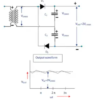
A full-wave doubler also uses diodes and capacitors to produce an output close to twice the input peak voltage. In a common version, one capacitor charges on the positive half-cycle and the other charges on the negative half-cycle. Their stored voltages are connected in series across the output, so the voltages add.
The ideal output is approximately:
V_{\text{out}} \approx 2V_{\text{peak}}
Because one output capacitor is charged during each half-cycle, the output ripple frequency is approximately twice the AC supply frequency:
f_{\text{ripple}} \approx 2f_{\text{input}}
The higher ripple frequency can make filtering easier for a given application. However, the circuit’s grounding and connection to the AC source depend on its particular topology. Some full-wave doubler arrangements do not share a common ground between input and output.
Half-wave and full-wave doublers compared
| Feature | Half-wave doubler | Full-wave doubler |
|---|---|---|
| Ideal light-load output | About twice the input peak | About twice the input peak |
| Output capacitor charging | Once per AC cycle | Capacitors charge on alternate half-cycles |
| Approximate ripple frequency | Same as input frequency | Twice the input frequency |
| Grounding | Depends on the circuit design | Depends on the circuit design |
| Main practical limitation | Output falls and ripple grows under load | Output also falls under load; topology and component ratings matter |
The labels “half-wave” and “full-wave” describe how the circuit uses the input cycles to charge its capacitors. They do not mean that a real output remains perfectly constant.
Voltage tripler and quadrupler
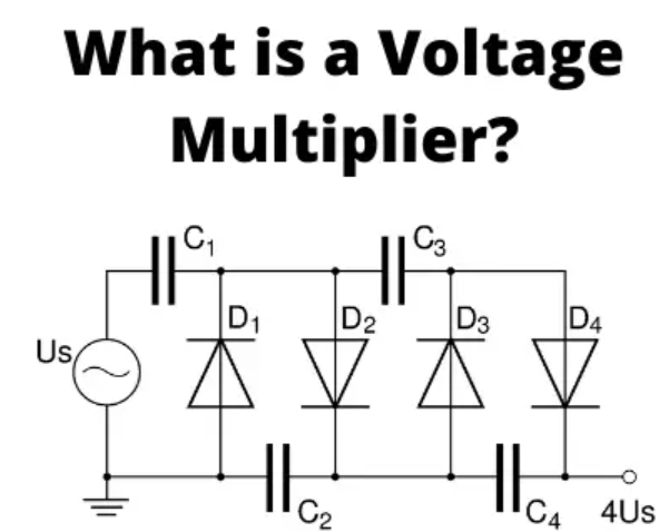
A voltage tripler aims to produce about three times the input peak voltage. A quadrupler aims for about four times the input peak voltage. These circuits extend the diode-capacitor arrangement so that the voltages stored on multiple capacitors add together.
For an ideal multiplier with multiplication factor n, the approximate no-load output is:
V_{\text{out}} \approx nV_{\text{peak}}
For a tripler:
V_{\text{out}} \approx 3V_{\text{peak}}
For a quadrupler:
V_{\text{out}} \approx 4V_{\text{peak}}
These are ideal estimates. Under load, the output voltage is lower and may have more ripple. As sections are added, the circuit also becomes more affected by component tolerances, leakage and the current drawn by the load. High-voltage multiplier ladders, including Cockcroft-Walton circuits, use repeated diode-capacitor sections to produce still higher voltages. MIT lecture notes on voltage multipliers
Why the output drops under load
A capacitor stores charge and supplies the load between the brief moments when a diode conducts and recharges it. If the load draws more current, the capacitor loses more charge before the next charging pulse. The average output voltage drops and the ripple increases.
A useful qualitative guide is:
- Lighter load: less charge is taken from the capacitors; output is closer to the ideal value.
- Heavier load: more charge is taken; output voltage falls and ripple grows.
- Larger capacitance: more charge can be stored, which usually reduces ripple for the same load and frequency.
The actual output depends on the circuit, capacitance, input frequency, diode characteristics and load. Calculating the exact ripple requires those details.
Worked examples
Example 1: Estimate the output of a doubler
A half-wave voltage doubler is connected to a sine-wave source rated at 24 V RMS. Estimate its ideal no-load output.
First convert the RMS voltage to peak voltage:
V_{\text{peak}} = \sqrt{2}\times24\ \text{V} \approx 33.9\ \text{V}
Then estimate the output of an ideal doubler:
V_{\text{out}} \approx 2\times33.9\ \text{V} \approx 67.8\ \text{V}
The ideal no-load estimate is approximately 68 V. A real output will be lower, especially when a load is connected.
Example 2: Estimate the output of a tripler
A tripler receives an AC input with a peak voltage of 15 V. Estimate its ideal no-load output.
V_{\text{out}} \approx 3\times15\ \text{V} = 45\ \text{V}
The ideal no-load estimate is 45 V. The practical output will be lower because of diode drops, capacitor losses and the load.
Example 3: Find the ripple frequency of a full-wave doubler
A full-wave doubler is connected to a 50 Hz AC supply. Estimate the ripple frequency.
f_{\text{ripple}} \approx 2\times50\ \text{Hz} = 100\ \text{Hz}
The ripple frequency is approximately 100 Hz.
Applications
Voltage multipliers are useful in circuits that need high voltage while drawing relatively little current. Applications can include:
- Cathode-ray tubes and some older display equipment
- High-voltage sections of some X-ray systems
- Laser power supplies
- Ion pumps and other scientific instruments
- Photomultiplier tubes
- Copy machines and electrostatic equipment
- Travelling-wave tubes
Whether a multiplier is suitable depends on the voltage, current, ripple, size and reliability requirements of the application. High-voltage systems may use other power-supply designs when they need substantial current or tightly regulated output.
Common mistakes to avoid
- Using RMS voltage as though it were peak voltage. Convert the input to peak voltage before estimating an ideal multiplied output.
- Treating the ideal output as guaranteed. The load and circuit losses reduce the actual output.
- Assuming all doublers have the same grounding. Grounding depends on the topology.
- Mixing up input frequency and ripple frequency. A half-wave doubler typically recharges its output once per cycle; a full-wave doubler typically recharges on both half-cycles.
- Assuming a voltage multiplier can supply high voltage and high current at the same time. Multiplier circuits are generally most useful for relatively low-current loads.
- Ignoring component ratings. Diodes and capacitors must be selected for the voltages and currents they experience in the particular circuit.
Safety note
Voltage multipliers can produce output voltages much higher than their AC input. Capacitors may remain charged after power is disconnected. High voltage can cause severe injury or death, even when the available current seems small.
Do not touch or test a high-voltage multiplier unless you are trained, have appropriate equipment and follow established high-voltage safety procedures. Capacitors must be discharged safely using equipment rated for the circuit voltage.
Quick summary
An ideal voltage doubler produces approximately twice the AC peak input voltage:
V_{\text{out}} \approx 2V_{\text{peak}}
An ideal tripler produces approximately three times the peak:
V_{\text{out}} \approx 3V_{\text{peak}}
An ideal quadrupler produces approximately four times the peak:
V_{\text{out}} \approx 4V_{\text{peak}}
A half-wave doubler typically has ripple at the input frequency. A full-wave doubler typically has ripple at twice the input frequency. In both circuits, the output falls below its ideal value when loaded.
Conclusion
A voltage multiplier combines diodes and capacitors to convert an AC input into a higher DC voltage. In a doubler, capacitor voltages add to produce an ideal output near twice the input peak. Additional sections can produce tripled, quadrupled or higher voltages.
The ideal multiplication factor is only a starting estimate. The real output depends on the load, component values, input frequency and circuit design. Always distinguish peak voltage from RMS voltage, check component ratings and treat multiplier outputs as hazardous.
For reference, a university electronics lab explains the capacitor charging action in a basic doubler, while MIT lecture notes illustrate doubler and quadrupler arrangements. Carnegie Mellon voltage-multiplier lab, MIT voltage-multiplier lecture notes.