
CONSTRUCTION OF ELECTRICAL REMOTE CONTROL MOTOR CAR
PREPARED BY:
Soyombo oluwajuwonlo gabriel 2018702030240
Sangodoyin ajibola mujeeb 2018702030237
Sowunmi sunday Joseph 2018702030239
Sunmonu akinkunmi quadri 2018702030241
Fadare temitayo Lawrence. 2018702030121
Oyelabi Timileyin Samuel. 2016070203234
A PROJECT REPORT SUBMITTED OF ELECTRICAL ENGINEERING IN PARTIAL FULFILLMENT FOR THE AWARD OF NATIONAL DIPLOMA
FACULTY OF ENGINEERING
THE POLYTECHNIC IBADAN
MARCH, 2021.
AUTHENTICATION
I hereby certify that this project work “CONSTRUCTION OF A REMOTE CONTROL MOTOR CAR” was carried out by:
Soyombo oluwajuwonlo gabriel 2018702030240
Sangodoyin ajibola mujeeb 2018702030237
Sowunmi sunday Joseph 2018702030239
Sunmonu akinkunmi quadri 2018702030241
Fadare temitayo Lawrence. 2018702030121
Oyelabi Timileyin Samuel. 2016070203234
of the Department of Electrical Engineering, The Polytechnic, Ibadan.
________ ____
MR. S.O. OLAYIWOLA
Supervisor
________ ____
ENGR. M.O. SADIQ
Head of Department
TABLE OF CONTENTS
TITLE PAGE. i
AUTHENTICATION ii
TABLE OF CONTENT. iii
CHAPTER ONE
1.1 INTRODUCTION 1
1.2 BACKGROUND OF THE PROJECT 1
1.3 PROBLEM STATEMENT 1
1.4 AIM OF THE PROJECT 2
1.5 OBJECTIVE OF THE PROJECT 2
1.6 SIGNIFICANCE OF THE PROJECT 2
1.7 BENEFIT OF THE STUDY 2
1.8 LIMITATION OF THE PROJECT 2
1.9 DEFINITION OF TERM 3
CHAPTER TWO
2.0 LITERATURE REVIEW 4
2.1 LITERATURE REVIEW OF REMOTE TECHNOLOGY 4
2.2 HISTORICAL BACKGROUND OF REMOTE CONTROL 5
2.3 REVIEW OF DIFFERENT TYPES OF REMOTE CONTROL CAR 9
CHAPTER THREE
3.0 METHODOLOGY 12
3.1 INTRODUCTION 12
3.2 BLOCK DIAGRAM OF THE SYSTEM 12
3.3 BLOCK DESCRIPTION 13
3.4 ELECTRONIC COMPONENTS USED 14
3.5 CIRCUIT DESIGN OF REMOTE CONTROL CAR 14
REFERENCE 18
ABSTRACT
This work is on a remote control motor car. Remote controlled car is battery/ powered model cars or trucks that can be controlled from a distance using a specialized transmitter or remote. This Radio controlled system is adopted in many vehicles like cars, boats, planes, and even helicopters and scale railway locomotives. In this work we will use a couple of ICs and a motor fixed to a chassis to make a remote control car. This work involve a brief idea is to transmit control signals through radio frequency and receive it through a receiver module in the car. We will have two switches in our remote control to power each motor of the car.
The objective of this project is to design a low cost remote control toy or robot. In this work we shall assemble the motors, circuit, and wheels on the chassis.
TABLE OF CONTENTS
TITLE PAGE
APPROVAL PAGE
DEDICATION
ACKNOWELDGEMENT
ABSTRACT
TABLE OF CONTENT
CHAPTER ONE
INTRODUCTION
BACKGROUND OF THE PROJECT
PROBLEM STATEMENT
AIM OF THE PROJECT
OBJECTIVE OF THE PROJECT
SIGNIFICANCE OF THE PROJECT
BENEFIT OF THE STUDY
LIMITATION OF THE PROJECT
PROJECT ORGANISATION
CHAPTER TWO
LITERATURE REVIEW
2.0 LITERATURE REVIEW
2.1 LITERATURE REVIEW OF REMOTE TECHNOLOGY
2.2 HISTORICAL BACKGROUND OF REMOTE CONTROL
2.4 REVIEW OF DIFFERENT TYPES OF REMOTE CONTROL CAR
CHAPTER THREE
3.0 METHODOLOGY
3.1 INTRODUCTION
3.2 BLOCK DIAGRAM OF THE SYSTEM
3.3 BLOCK DESCRIPTION
3.4 ELECTRONIC COMPONENTS USED
3.5 CIRCUIT DESIGN OF REMOTE CONTROL CAR
CHAPTER FOUR
RESULT ANALYSIS
4.1 CONSTRUCTION PROCEDURE
4.2 ASSEMBLING OF SECTIONS
4.3 MOUNTING PROCEDURE
4.4 TESTING
4.5 RESULT
4.6 ECONOMIC OF THE PROJECT
4.7 RELIABILITY
4.8 MAINTAINABILITY
4.9 PROJECT EVALUATION
4.10 BILL OF ENGINEERING MEASUREMENTS AND EVALUATION
CHAPTER FIVE
CONCLUSIONS
RECOMMENDATION
5.3 REFERENCES
CHAPTER ONE
1.0 INTRODUCTION
1.1 BACKGROUND OF THE STUDY
Remote control car referred to as RC Car, RC is short for Radio control or Remote control. In Europe, Japan and Southeast Asian countries, the remote control model car race is a kind of sports competitions and a noble sport, even a high-tech hobby. This is a competition from age limit because enthusiasts who participate in this sport is aged from 8 to 80 years. This also suggests that the remote control cars is the same as remote control aircraft, whether adult or children can play. However, it has a certain degree of risk, because the remote control car is not a simple toy, its principle is the same as the real car. So, I still recommend that children would better to accompany by their parents.
Electric remote control car is primarily provided power by an electric motor. Due to powered by a battery, it has higher overall operating efficiency and excellent acceleration performance of vehicles. Because of Clean Energy, the vehicle maintenance is very convenient, just pay attention to the maintenance of transmission parts. But because the electric motor remote control car need high requirements of motor performance and battery performance, so the motor and battery consumption is very high in the beginning, coupled with the electronic speed control, remote equipment costs.
1.2 PROBLEM STATEMENT
Kids using manual car as fun or for recreation involved physical strength and sometimes can be hazardous in that they can be injured whenever the car crash with an object or obstacle. However, this device can overcome this problem. This device does not involve physical strength in that the motor is been controlled wirelessly using remote.
1.3 AIM OF THE PROJECT
This project was aimed at building a wireless remotely controlled motor car. It involves using a remote to control movement and direction of a car.
1.4 OBJECTIVES OF THE STUDY
The objective of this project is to design a low cost remote control toy or robot. There are so many projects available to make motor toys. But here we are providing a simple circuit with low cost electronics components.
1.5 SIGNIFICANCE OF THE STUDY
It is very useful to study the basics of wireless communication for electronics beginners. Mainly wireless car projects use two types of technologies Infra-Red (IR) and Radio Frequency (RF). IR remote control sends infrared rays to the car circuit. In case of IR remote control, line of sight with the receiving circuit is necessary and its range is only up to 10 meters. But in case of RF remote Radio Frequency waves plays the role, so signal can go through walls and are able to provide a range up to 35 meters.
1.6 BENEFIT OF THE STUDY
Playing with RC cars can significantly develop and improve a child’s visual-motor coordination. This is the ability to coordinate visual information with motor output. Along with this skill is visual perception, which is the ability to recognize, recall, discriminate and make sense of what we see.
RC car play enhances spatial awareness spatial intelligence and awareness skills, which results in increased dexterity. In addition, kids learn about cause-and-effect during play as they work out which buttons make the car go in each direction.
While playing with other children, it also teaches them to swerve around obstacles they can’t control.
And it is no stretch to say that playing with remote control cares promotes creativity and imagination. While adults may be content to have their cars zip around a parking lot, or engage in structured games or competition, kids tend to use their imagination and create make-believe settings and scenarios.
1.7 LIMITATION OF THE PROJECT
This device was able to provide a range up to 35 meters. To operate this device becomes a problem when the remote is faulty or whenever the battery of the remote runs down
1.8 DEFINITION OF TERMS
1. RF Transmitter: Amplitude shift keying (ASKRF) transmitter module is a small PCB sub-assembly capable of transmitting a radio wave and modulating that wave to carry data. Transmitter modules are usually implemented alongside a microcontroller which will provide data to the module which can be transmitted.
2. RF Receiver: Amplitude shift keying (ASK RF) Receiver serial data and transmits it wirelessly through its RF antenna. The transmission occurs at the rate of 1Kbps–10Kbps. RF receiver receives the transmitted data and it is operating at the same frequency as that of the transmitter.
3. HT12E Encoder IC: HT12E is used to encode the data for RF Transmitter and HT12D is used to decode the data received by RF receiver. Product Features. The HT12E Encoder IC are series of CMOSLS Is for Remote Control system applications. They are capable of Encoding 12 bit of information which consists of 8 address bits and 4data bits.
4. HT12D Decoder IC: HT12D is a 212series decoder IC (Integrated Circuit) for remote control applications manufactured by Holtek. It is commonly used for radio frequency (RF) wireless applications.
5. L293D Motor Driver: L293D is a typical Motor driver or Motor Driver IC which allows DC motor to drive on either direction. L293D is a 16-pin IC which can control a set of two DC motors simultaneously in any direction. It means that you can control two DC motor with a single L293DIC.
6. LED: Light Emmiting Diode it serves as flow of connection from the remote control to the motor car.
Resistor 1k: It resist the current of the motor, which serves as brake to the remote car
Battery: 9V/12V it is been used to power the circuit.
CHAPTER TWO
LITERATURE REVIEW
In this chapter all the literature and terms related to this work are reviewed.
2.1 LITERATURE REVIEW OF REMOTE TECHNOLOGY
By the early 1980s, the industry moved to infrared, or IR, remote technology. The IR remote works by using a low frequency light beam, so low that the human eye cannot see it, but which can be detected by a receiver in the TV. Zenith’s development of cable-compatible tuning and teletext technologies in the 1980s greatly enhanced the capabilities and uses for infrared television (TV) remotes. Today, remote control is a standard feature on other consumer electronics products, including video cassette recorders (VCRs), cable and satellite boxes, digital video disc players and home audio receivers. And the most sophisticated TV sets have remotes with as many as 50 buttons.
Zenith developed the world’s first wireless trackball TV remote control, called Z-Trak. The remote works like a computer mouse – click the ball and a cursor appears on the TV screen. Roll the ball and the cursor activates control menus hidden in different corners of the screen. Then, activate something from those menu bass, treble, contrast, colour temperature, and channel [5, 6, 7].
According to Sajidullah S. Khan, Anuja Khodustar and Koli, N.A who worked on Home automation appliance (2011) and striking results were obtained in terms of reduction in delay time between the transitions of streams from client to server using Java enabled program.
More so, Kai-Hung Liang, Kuo-Han Kan, and Szu-Chi Tien (2013) who carried out work on the precision positioning with shape-memory-alloy actuators. The result obtained using the inversion of non-linear model with model-reference-adaptive system (MRAS) was robust as regards to external disturbances and the positioning performance [1].
2.2 HISTORICAL BACKGROUND OF REMOTE CONTROL
The earliest example of remote control by radio waves was developed in 1898 by Nikola Tesla and described in his patent, U.S. Patent 613,809, named Method of an Apparatus for Controlling Mechanism of Moving Vehicle or Vehicles. In 1898, he demonstrated a radio-controlled boat to the public during an electrical exhibition at Madison Square Garden. Tesla called his boat a “teleautomaton”.
In 1903, Leonardo Torres Quevedo presented the Telekino at the Paris Academy of Science, accompanied by a brief, and making an experimental demonstration. In the same time he obtained a patent in France, Spain, Great Britain, and the United States. The Telekino consisted of a robot that executed commands transmitted by electromagnetic waves. With the Telekino, Torres-Quevedo laid down modern wireless remote-control operation principles and was a pioneer in the field of remote control. In 1906, in the presence of the king and before a great crowd, Torres successfully demonstrated the invention in the port of Bilbao, guiding a boat from the shore. Later, he would try to apply the Telekino to projectiles and torpedoes, but had to abandon the project for lack of financing.
The first remote-controlled model aeroplane flew in 1932, and the use of remote control technology for military purposes was worked intensively during the Second World War, one result of this being the German Waterfall missile.
By the late 1930s, several radio manufacturers offered remote controls for some of their higher-end models. Most of these were connected to the set being controlled by wires, but the Philco Mystery Control (1939) was a battery-operated low-frequency radio transmitter, thus making it the first wireless remote control for a consumer electronics device.
Television remote controls
The first remote intended to control a television was developed by Zenith Radio Corporation in 1950. The remote, called “Lazy Bones”, was connected to the television by a wire. A wireless remote control, the “Flashmatic”, was developed in 1955 by Eugene Polley. It worked by shining a beam of light onto a photoelectric cell, but the cell did not distinguish between light from the remote and light from other sources. The Flashmatic also had to be pointed very precisely at the receiver in order to work.[7]
In 1956, Robert Adler developed “Zenith Space Command”, a wireless remote. It was mechanical and used ultrasound to change the channel and volume. When the user pushed a button on the remote control, it clicked and struck a bar, hence the term “clicker”. Each bar emitted a different frequency and circuits in the television detected this sound. The invention of the transistor made possible cheaper electronic remotes that contained a piezoelectric crystal that was fed by an oscillating electric current at a frequency near or above the upper threshold of human hearing, though still audible to dogs. The receiver contained a microphone attached to a circuit that was tuned to the same frequency. Some problems with this method were that the receiver could be triggered accidentally by naturally occurring noises, and some people could hear the piercing ultrasonic signals. There was an incident in which a toy xylophone changed the channels on such sets because some of the overtones from the xylophone matched the remote’s ultrasonic frequency.
The impetus for a more complex type of television remote control came in 1973, with th upe development of the Ceefax teletext service by the BBC. Most commercial remote controls at that time had a limited number of functions, sometimes as few as three: next channel,
previous channel, and volume/off. This type of control did not meet the needs of teletext sets, where pages were identified with three-digit numbers. A remote control to select teletext pages would need buttons for each numeral from zero to nine, as well as other control functions, such as switching from text to picture, and the normal television controls of volume, channel, brightness, colour intensity, etc. Early teletext sets used wired remote controls to select pages, but the continuous use of the remote control required for teletext quickly indicated the need for a wireless device. So BBC engineers began talks with one or two television manufacturers, which led to early prototypes in around 1977–1978 that could control many more functions. ITT was one of the companies and later gave its name to the ITT protocol of infrared communication.
In 1980, a Canadian company, Viewstar, Inc., was formed by engineer Paul Hrivnak and started producing a cable TV converter with an infrared remote control. At the time the most popular remote control was the Starcom of Jerrold (a division of General Instruments) which used 40-kHz sound to change channels. The Viewstar converter was an immediate success, the millionth converter being sold on March 21, 1985, with 1.6 million sold by 1989.
In 2006, Hillcrest Labs introduced the Loop pointer, a remote control that used Hillcrest’s Freespace motion control technology to allow users to control their televisions with natural gestures. The Loop had just four buttons and a scroll wheel. Freespace-enabled remote controls use radio waves to communicate with a USB antenna connected to a computer that is also connected to the television, so they do not need to be pointed at the PC, or even have a direct line of sight.
Some television manufacturers now include Bluetooth remotes to control the television without requiring line of sight, overcoming the limited range in IR-based remotes.
Effect of the early television remote control
The remote allowed audiences, for the first time, to interact with their TV without using the buttons on the TV. They no longer watched programs just because they did not want to get up to change the channel. They could also channel surf during commercials, or turn the sound off.
The invention of the remote control has led to several changes in television programming. One was the creation of split screen credits. According to James Gleick, an NBC research team discovered that when the credits started rolling after a program, 25% of its viewers would change the channel before it was over. Because of this, the NBC 2000 unit invented the “squeeze and tease” which squeezed the credits onto one third of the screen while the final minutes of the broadcast aired simultaneously.
The remote control also led to an adjustment in commercial airings. Networks began to feel that they could not afford to have commercials between programs because it would detract viewers from staying tuned into their channel. Programmers decided to place commercials in the middle of programs to make the transition to the next show direct.
Other remote controls
In the 1980s Steve Wozniak of Apple started a company named CL 9. The purpose of this company was to create a remote control that could operate multiple electronic devices. The CORE unit (Controller Of Remote Equipment) was introduced in the fall of 1987. The advantage to this remote controller was that it could “learn” remote signals from different devices. It had the ability to perform specific or multiple functions at various times with its built-in clock. It was the first remote control that could be linked to a computer and loaded with updated software code as needed.
The CORE unit never made a huge impact on the market. It was much too cumbersome for the average user to program, but it received rave reviews from those who could. These obstacles eventually led to the demise of CL 9, but two of its employees continued the business under the name Celadon. This was one of the first computer-controlled learning remote controls on the market.
The proliferation of remote controls
By the early 2000s, the number of consumer electronic devices in most homes greatly increased, along with the number of remotes to control those devices. According to the Consumer Electronics Association, an average American home has four remotes. To operate a home theater as many as five or six remotes may be required, including one for cable or satellite receiver, VCR or digital video recorder (DVR/PVR), DVD player, TV and audio amplifier. Several of these remotes may need to be used sequentially but, as there are no accepted interface guidelines, the process is increasingly cumbersome.
Many specialists, including Jakob Nielsen, a renowned usability specialist, and Robert Adler, the inventor of the modern remote, note how confusing, unwieldy and frustrating the multiplying remotes have become. Because of this proliferation of remote controls, universal remote controls that manage multiple devices are becoming increasingly popular.
2.3 REVIEW OF DIFFERENT TYPES OF REMOTE CONTROL CAR
According to different classification of motivation, remote controlled car classified as below:
1. Oil move RC car: Oil move remote control model car is powered by a fuel engine, it also can be divided into classified according to the type of fuel. Fuel powered engine has the advantage of powerful, it has high degree of onomatopoeia vehicle model simulation, and can give players a real feel. The advantages is large fuel. If there is leakage, the maintenance will be very troublesome. In addition, since the fuel is added to increase the engine power output compounds that are corrosive, so vehicles need to do careful corrosion protection, maintenance cost is not small.
2. Electric remote control car: Electric remote control car is primarily provided power by an electric motor. Due to powered by a battery, it has the higher the overall operating efficiency and excellent acceleration performance of vehicles. Because of Clean Energy, the vehicle maintenance is very convenient, just pay attention to the maintenance of transmission parts. But because the electric motor remote control car need high requirements of motor performance and battery performance, so the motor and battery consumption is very high in the beginning, coupled with the electronic speed control, remote equipment costs. If you want to run an electric model cars, you will be basically going to spend over 2000, which is one of reason to make electric remote control model car restrictions. According to the remote control car driver type and shape classification
3. SUV: SUV can be seen as a flat road car variant, the chassis is also a flat shape. But diameter of tires is much larger, suspension travel has also increased, which is mainly to increase the performance of the vehicle through performance. At the same time to increase vehicle power, SUV also need to put forward higher requirements in vehicle steering or other aspects of the vehicle on-board electronic systems, such as the need for greater torque servo steering gear to provide powerful steering torque, etc.. The advantages of SUV is that to retains the high-speed performance and increase through performance. That is a relatively funny remote control car.
4. Monster Truck: Do not think that big wheels can be called monster truck. Monster truck is relatively flat road cars and SUV, it has its own unique characteristics. In addition to large wheels, truck biggest feature is hardly a vehicle chassis, to support vehicles parts transmission and axle systems are generally appeared in the form of frames and side plates, as if all the parts are ” hanging” on the frame. The benefits is to improve the off-road performance. The bottom of the car can be made arch to meet the rugged road, so the car has high playability. According to the different speeds, it can be graded, ordinary monster and climb monster truck. The climb monster truck is mainly designed to climb the rugged road, a huge vehicle torque, but in order to meet the torque and stability, the speed will be very slow. vehicle work requirement is very high, the price does not poor.
5. Flat road car: Flat road vehicles are concerned for RVs and cars, because of its low chassis, chassis plate-like, vehicles through poor performance, but the straight line stability and acceleration are the most superior. Two -wheel-drive flat road car is mainly used for racing, flat road four-wheel drive sports car for racing, drift race, etc.
CHAPTER THREE
METHODOLOGY
3.1 INTRODUCTION
In this project we are designing an RF remote control. For that we are using an ASK transmitter receiver module. Microcontroller is avoided in the circuit to make it cost effective. ASK module is used as the remote transmitter, two IC’s HT12E and HT12D is used for Encoding and Decoding. Circuit diagram and circuit explanation given below will help the reader to understand how a remote control car.
3.2 BLOCK DIAGRAM OF REMOTE CONTROL CAR
Before carrying out any project, the block diagram must be drawn and fully understood. Block diagram gives a pictorial understanding of any work. The block diagram of the system is as below:
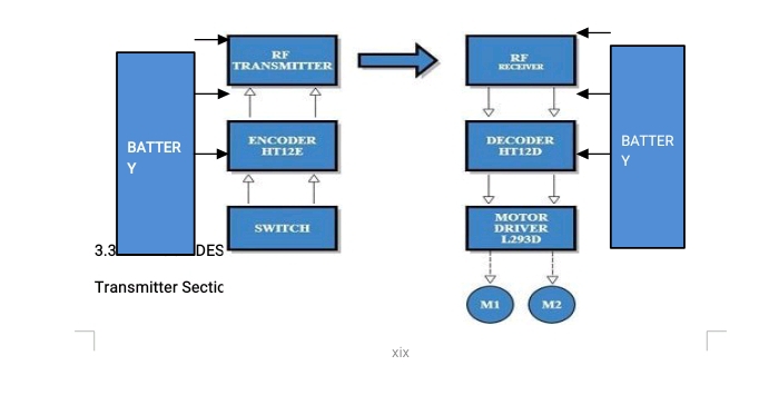
Block diagram of remote control car
3.3 BLOCK DESCRIPTION
Transmitter Section:
Controlling Switches: Four button switches are used in the remote control to move the car backward, forward, left and right.
HT12E Encoder IC: It is a 212 series encoder IC used for wireless communication applications. It is mainly used to convert 12 bit parallel data (8 address bits and 4 data bits) to serial out so that it can be transmitted using a transmitter Module.
RF Tx Module: 434 MHz ASK transmitter module for transmission. It is capable of providing a data rate of about 8kbps.
Battery: 3V button cell is used to power the remote.
Receiver Section:
RF Rx Module: A high sensitivity 434 MHz ASK Receiver module for receiving the data from remote control.
HT12D Decoder IC: It is a 1212 series decoder IC used for wireless communication applications. It converts the serial input to parallel out.
Motor Driver: L293D motor driver is used to drive two motors. L293D provides bidirectional drive current up to 600mA at voltages from 4.5V to 36V.
Motors: Here two BO motors are used which are driven by the motor driver L293D and both of them are connected to robotic wheels to move the car.
Battery: Receiver section need more power than the remote control circuit. So 9V/12V battery is required to power the circuit.
3.4 ELECTRONIC COMPONENTS USED
Only basic electronic components were used here for the project. All datasheets and link to buy the components online are provided below:
Resistor:
1K Resistor: 8
Semiconductors:
HT12E Encoder IC: 1
HT12D Decoder IC: 1
Modules:
ASK RF Transmitter: 1
ASK RF Receiver: 1
L293D Motor Driver: 1
Miscellaneous:
3V Button Cell with holder (Remote): 1
9V/12V Battery with holder (Receiver/Car): 1
Button Switch: 4
BO Motor: 2
Robotic Wheels: 4
3.5 CIRCUIT DESIGN OF REMOTE CONTROL CAR
The circuit diagram of the device is as below:
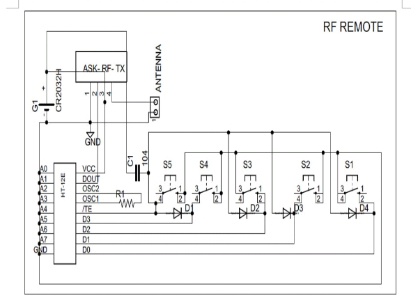
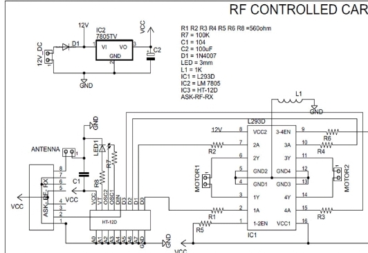
Rc car circuit diagram with remote control
RC car circuit diagram with remote transmitter
Circuit design of this remote control car is simple and is of low cost as we are not using a microcontroller in it. Main components are two communication ICs (HT12D and HT12E) and an ASK RF transmitter receiver module.
RC car circuit diagram with remote transmitter is designed in a compact way to make it as small as possible. Remote uses four button switches (S1, S2, S3, and S4) to control the toy. Digital data’s from the switches are encoded by the HT12E encoder IC and are transmitted to the receiver through ASK RF Module. When we press these switches, 4 data bits and 8 address bits are serially encoded and output through the pin “DOUT” is given to the 434 MHz Transmitter. Circuit is so simple due to the simple coupling of ASK module with HT12E and HT12D pair. Remote control is power by a 3V button cell.
Receiver section receives the signal with the help of 434 MHz ASK module and provides it to the decoder IC. “DIN” pin of HT12D gets the data from RF module and checks it three times before decoding. And if received address data matches with the encoder address data, then IC will decode the data bits and provides it directly to L293D motor driver. This driver is used to control the motors forward and backward according to the received signal. An LED is connected to the valid transmit pin of Decoder IC to indicate a valid transmission.
Left Motor Direction
Right Motor Direction
Direction of Car
| LEFT MOTOR DIRECTION | RIGHT MOTOR DIRECTION | DIRECTION OF CAR |
| forward | forward | forward |
| forward | Backward | right |
| backward | forward | left |
| backward | backward | backward |
CHAPTER FOUR
4.0 RESULT ANALYSIS
4.1 CONSTRUCTION PROCEDURE
In building this project, the following procedures were properly considered,
I. Purposing of the entire materials / Components needed
ii. Resistance check of the components bought with the help of ohmmeter before making the necessary connection with the components
iii. Drafting out a schematic diagram or how to arrange the materials / components.
iv. Testing the completed system to see if the design works and
v. Finally, implementation of design of the project.
Having procured all the materials, I processed into the arrangement of the components into the Vero board but we could not laid the ics directly on the bread board because the heat soldering iron emits while soldering, proper soldering of the components then followed. The components were all soldered into the board after which it was correctly confirmed done.
4.2 ASSEMBLING OF SECTIONS
Having provided the casing and having finished the construction of the sections of this system, the assembling into the casing followed. The sections were properly laid out and assembled into the casing where the general coupling and linkages into the peripheral devices took place.
4.3 MOUNTING PROCEDURE
The transformer was bolted directly to the bottom of the case. This was followed by mounting of the power section of the circuit board. A gap was made between one mounting and the successive ones. This is necessary to avoid overcrowding. The vero board is also mounted at the upper side of the case. The resistors, transistors, and other components used were mounted on the vero board. All the accessories were highly fixed to avoid slack that may result in the process of operations
4.4 TESTING
After implementing the circuit on a project board, the different sections of the complete system were tested to ensure that they were in good operating condition. The continuity test carried out is to ensure that the circuit or components are properly linked together. This test was carried out before power was supplied to the circuit. Finally, after troubleshooting has been done on the whole circuit, power was supplied to the circuit. Visual troubleshooting was also carried out at this stage to ensure that the components do not burn out.
4.5 RESULT
The results obtained during the construction states after necessary troubleshooting were satisfactory. The system was able to respond to its operation.
4.6 ECONOMIC OF THE PROJECT
Although this project has not been given due recognition by the authority concerned, whenever this equipment finds its use the case is relatively cheap with a good efficiency and improves on its reliability. Due attention will be given to the viability of this project reliability maintainability and also the evaluation.
4.7 RELIABILITY
In the design of the remote control motor car with bidirectional rotation, reliability is taken into consideration to improve on the system performance. Here the concept of reliability has been associated, in a qualitative way with good design endurance consistence quality and dependability in recent years however, the much greater complexity of the line selector and the seriousness of a failure in the system have made it necessary to attempt not only to improve the reliability of the equipment but also to assesses it in qualitative terms.
In order to appreciate some of the difficulties which are involved in the designed of this project, imagine a discussion concerning the relative merits of remote control motor car in the first place the specifications of the picture quality and staying. The discussion may then turn to the likelihood of faults developing in the sets. This is important not only because of the annoyance caused to the viewer by a failure but pay a higher initial cost for an automatic change over switch in return for an assurance that the extra cost will mean smaller maintenance costs. Therefore, from this little explanation, “Reliability can be defined as the characteristics of a component or of a system which may be expressed by the probability that it will perform a required function under started conditions for a specified period of time.
4.8 MAINTAINABILITY
In this design and construction of this project (remote control motor car), it is usually very important to note that maintainability is another area or aspect taken into consideration since high initial or production cost will lead to a low maintenance cost. The remote control motor car has a high input output-performance, but relatively cheap, easy and low maintenance cost.
Therefore maintainability of the probability that a device will be restored to operational effectiveness within a given period of time when the maintenance action as performance in accordance with prescribed procedures”.
4.9 PROJECT EVALUATION
Considering the cost of this project one must note that fact that it is not mass production. As such to single handedly manufacture it without any industrial aided production machine will in no doubt in our much expenses, the initial market survey did not prove successful due to irregular price of item such as those used in this project.
4.10 BILL OF ENGINEERING MEASUREMENTS AND EVALUATION
The expenditure made in purchasing all the components / materials and quantity used in building this project is tabulated as show below.
CHAPTER FIVE
5.1 CONCLUSION
In this work, remote controlled motor car was implemented. The proposed system was built and a satisfactory result was achieved. Controller executes the load to rotate “FORWARD” and “REVERSE” direction depending upon the input we are giving the virtual terminal via the remote.
5.2 RECOMMENDATIONS
The device has been designed, tested and system was able to respond to its operation. This work was built with quality wiring and contains many connections, I recommend that if failure occur, it should be troubleshoot by a qualify personnel along with the circuits diagram.
This project was built for Educational purposes. If one wants to use it for industrial or home applications, I recommend that a hook should be attached to the casing that would allow fixing the system on the wall.
Working on this topic as my project is a good idea and it comes at the right time. I am suggesting that this particular topic should also be given to other students both in higher and lower class.
REFERENCES
[1] IIT BOMBAY, TECHFEST 2010-11, PDF’s.
[2] http://www.meadinfo.org/2009/07/design-and-fabrication-of-icengine.
html
[3] https://en.wikipedia.org/wiki/Radio-controlled_car
[4] http://www.rcuniverse.com/forum/forum.php
[5] http://www.rc-help.com/forum.php
[6] http://www.rctech.net/forum/
[7] Y. Ege , M. G. Sensoy , O. Kalender , S. Nazlibilek , H. Citak, J. Mesurement 46 (2013)
[8] A. A. F. Nassiraei , K Ishii, Concept of Intelligent Mechanical Design for Mobile Robots J. Bion. Engg 4 (2007)
[9] G. Yasuda, Distributed Autonomous Control of Modular Robot Systems Using Parallel
Programming, J. Mat. Proc. Tech. 141 (2003)
[10] S. Dearden, Develop Large-Scale Embedded Designs, Electron Des.40 (1992)
[11] https://maker.pro/pcb/projects/remote-control-car
[12] https://www.google.com/amp/s/www.instructables.com/How-to-Make-a-Remote-Control-Car/%3famp_page=true#cobssid=s
Pingback: northwestpharmacy