
ELECTRICAL TERMS YOU SHOULD KNOW!
Accessories: A device other than current using equipment associated with such equipment or with the wiring of an installation.
Appliances: An item of current using equipment other than an illuminaries or an independent motor.
Cable coupler: A means enabling the connection of how cables are been connected. It consist of a connector and a plug.
Circuit: An assemble of electrical equipment supplied from the same origin and protected against over current by the circuit.
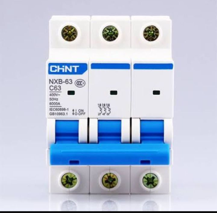
Circuit breaker: A mechanical switching device capable of making cutting and breaking current under specified abnormal circuit condition. For example the circuit breaker will trip-off if there’s short circuit.
Conductor: ( of a core or cable) the conducting portion consisting of a single wire or a group of wire in connect with each other for earthed concentric wiring. The metal in which electricity pass through in the cable sheet is called conductor.
Connector: The part of a cable coupler or an appliance coupler which is provided with female contact and is intended to be attached to the flexible cable connected to supplying.
Danger: Danger to health or danger to life or limb from shock, burn or injury from mechanical movement to a person due to electrical hazard.
Safety in the electrical engineering workshop
2. Workshop floor should be free from grease, oil and water to prevent electric workers from falling or stumbling and getting injured.
3. First aid must be available and equipped in the workshop.
4. Safety boots should be worn to prevent electrical hazard
5. The passage way to the workshop should be free from obstruction to allow free movement of workers.
6. Protective clothing such as rubber boots, gloves and eye googles shall be worn to prevent damage to insulation.
7. Tools must be checked before being used on life circuit or equipment to ascertain that there is no damage to insulation.
8. Machine lighting point and electrical circuit must be short down after work in the workshop.
General safety
- Observe all safety equipment.
- Ensure that you withstand instruction before commencing work anything you don’t understand, make sure you ask your instructor.
- Keep gangway sand access to fire appliances clear.
- Learn how to give first aid treatment for electric shock.
- Know where the nearest fire exit and what to do when there is an outbreak of fire.
- Report all accident to supervisor
- Never run, it is safer to walk
- Never panic, it is safer to be calm
- Never misuse anything provided for securing health of safety. Do not do anything likely to cause harm/danger to you or any other personnel in the workshop.
- Never make false alarm in the workshop
- When there is fire outbreak use the fire extinguisher to put off fire.
- Stay away from restricted access zone in the workshop.
- Never disobey your supervisor based on instruction given to you.
SAFETY TOOLS
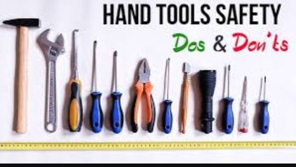
- Use the correct tool for the job.
- Inspect boot regularly, don’t use them if defective.
- Chisel or punches with butted or mushroom head should be redressed before use.
- When using screw driver, never hold the job on your hand it should be placed on the table.
- Tools with sharp point should never be carried unsheathed.
- Hammer or mallet with loosed handles should be tightened before use.
- When using a drive ensure that the meter being drilled is clamped.
- Spanner with spray jaws should not be used. They usually slip as pressure is applied.
- Always use a soldering iron stand. Never hang the soldering iron on equipment or lay it on a bench.
ELECTRICAL INSTALLATION TOOLS, APPLICATION AND MAINTENANCE
Electrical tools are equipment engaged to perform operation on electrical materials in order to achieve elected oriented results.
There are two types of tools
I . Hand tools
II . Machine tool
I . Hand tools: They are tools that can be used to carry out various works in the workshop through human effort. Examples are pliers, hammers, screwdrivers, tester, saw blades e.t.c
II . Machine tools: They are irons that can be used to carry out works on machine in the workshop through human operation e.g reading machine, electrical drilling machine, stone grinders e.t.c

Examples of Hand tools and maintenance
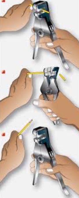
- Pliers (nose, side, cutter): iron be used for twisting cable, cutting cable and peeling of cable. Maintenance and care = it should not be used for hammering things. After use, keep it inside the tool box.
- Hammer: This is used for hammering nails. Maintenance: After use keep it inside the tool box
- Screwdriver: This is used for loosening or tightening screw of various sizes, it can be flat, star or both and we’ll insulated. Maintenance: it must be well insulated, keep it into the tool box after use.
- File: This is used for smoothening metal. Maintenance: After use keep it inside the tool box
- Hacksaw: This is used for cutting of tubes, pipes and metal. It must be insulated. Maintenance: After use keep it inside the tool box
- Tap and die: This can be used to for cutting internal thickness. Maintenance: it should be well cleaned and return back to the box after use.
- Soldering iron: it is used to join two pieces of wire together. Maintenance: Soldering bit should be cleaned immediately after use.
- Vernier calliper: it is used to measure in the workshop. Maintenance: it should be returned back to its box after use.
- Micrometer screw gauge: This is used for measuring the diameter of a single wire in the workshop. Maintenance: it should be well coiled and return back to the box after use
- Blow lamp: This is used for melting the joint of lead or soldered joint between two wires.
- Tester: This is used to test or checked if there is life connection in a socket of unknown node in wire connection.
- Multimeter: This is used to check the current, voltage, resistance, capacitance, , inductance in wire connection.
- Fuse element: a part of the fuse element is to melt when under abnormal condition e.g short circuit
- Cable coupler: a means of enabling the connection of two flexible cable. It consist of a cable and plug.
- Appliance: an item of current using equipment other than a luminaries or an independent motor.
- Switch board: an assembly of switch gear with or without instruments but the term does not apply to a group of local switches in final circuit.
- Socket outlet: a device provided with female contact, which is intended to be installed with the fixed wiring and intended to receive a plug.
- Circuit breaker: a mechanical switching device capable of making, carrying and breaking current under normal circuit condition and also of making for a specific time and breaking current under normal specific abnormal circuit condition such as short circuit.
- Insulation: These are materials that do not allow the flow of electricity to pass through them.
ELECTRICAL CABLE
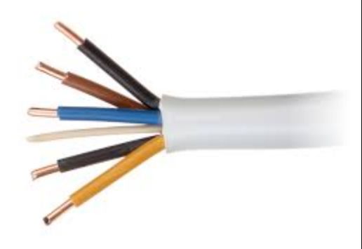
Cable is used in electrical circuit and consist of the following main parts.
mechanical protection ( outer part of the cable)
Insulator ( second layer of the cable)
Conductor ( third part that allow the free movement of electric current)
| Materials required | Quantity | S/N of mode of equipment used |
| 1.5mm, 2-core | 4-yard | Nwc |
| Sharp knife | 1 | Nwc |
| A pair of knife | 1 | Nwc |
Electrical cable properly trimmed
- Mechanical sheath (protection): This is provided to prevent damage to the electrical cable during installation and throughout it subsequent service.
- Insulation: This part don’t allow the free passage of an electrical current. Examples are mica, rubber, paper (impregnated paper), abestors and so many more.
WIRE
Wire in a cable contain conductor only. That is the part without electrical metal sheath or insulation part. Wire is a conductor material that is used for electrical wiring, it is the one without any form of insulation inside a cable.
TYPES OF CABLE
. Tough rubber-sheathed (T.R.S)
2 . Flexible cable and cord
3 . Paper insulated lead-covered (P.I.L.C)
4 . Lead sheathed (V.R.I)
5 . Poly-vinyl-chloride insulated and sheathed (P.V.C)
6 . Mineral insulated
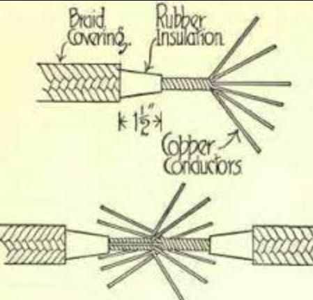
STRIPPING OF CABLE
The insulation and mechanical protection must be removed from the end of the cable to leave a suitable length of exposed conductor. On stripping a cable the following should be taken into consideration.
1 . The strands forming the core must not be cut or nicked, since this could results in a loss of conducting area or it could be a source of trouble as it may easily break completely at a later date.
2 . The insulation of the core must not be damaged when removing the outer covering. This particularly applied to most core cable such as P.V.C and T.R.S
3 . If any cable has an outer protection of cloth or tape such as lead sheath which usually has both, this must be removed to expose atleast half of inch of insulation.
CABLE TERMINATION
A . 13 Amps top plug
b . 13 Amps socket outlet
| Materials required | Quantity |
| 13 Amps Top plug | 1 |
| Sharp knife | 1 |
| 13 Amps socket outlet | 1 |
| Side cutter pliers | 1 |
| Pair pliers | 1 |
| Testing screw driver | 2 |
| 1.5mm, 3-core flexible cable | 200mm |
THEORY
Cable termination simply mean how cable stands are secured or joined into a terminal point. Cable termination could be done either by screwing it into a terminal or cable leg depending on the type of terminal available for termination.
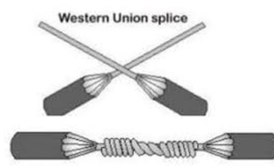
CABLE JOINT
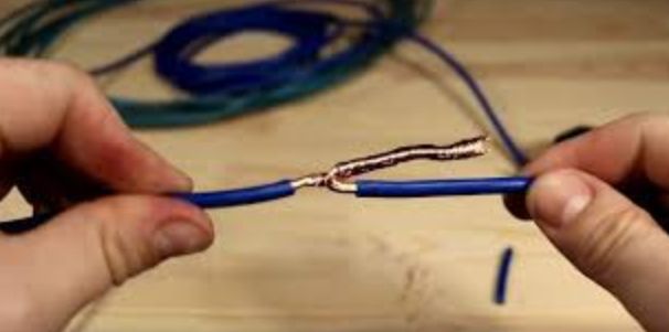
A joint is a place where two or more separate cables are brought together for the purpose of continuity. A good and reliable joint is achieved when two or more cables to be joined together are of the same materials e.g copper-to-copper or aluminum-to-aluminum.
Types of joint
1. Britannia joint: it is used in single overhead copper wire which are inconsiderable tension when in use
2. Scarf joint: it is suitable for all wires which are not required.
3. Straight twist joint
4. Tee twist joint
5. Married joint
6. Telescope joint
CONSTRUCTION OF BRITANNIA JOINT
| Materials required | Quantity | S/N of model or equipment |
| 1/2.5mm² cable | 200mm | Nwc |
| Pair of pliers | 1 | |
| Side cutter | 1 | |
| Soldering iron | 1 | |
| Sharp knife | 1 | |
| Soldering lead | 1 yard | |
| 1.13mm² wire | 200mm | Nwc |
PROCEDURE
1 . Strip and clean one end of each piece for 75mm.
2 . From the stripped end bend 6mm of each conductor at tight angle.
3 . Clamp the two conductor together with pliers so that the end are outwork.
4 . Tightly bind both conductor with 1.12mm² tune copper wire carrying the binding about 6mm
5 . Solder the whole length of the binding.
6 . Ask the workshop technician to check your work.
MARRIED JOINT
PROCEDURE
1 . Strip and clean one end each for 220mm.
2 . Twist strand of each piece for 35mm for each insulation.
3 . Untwist remainder of strands and straighten.
4 . Cut off center strands of each piece.
5 . Interspace the strands and bring the twisted portion together.
6 . Lightly bind the strands on the right-hand side round twist strand.
7 . Tightly bind the strands on the left-hand side round twisted strand against the leg of the cable.
8 . Untwist and straighten the strands on the right hand side then tightly bind them round twisted strand in the same direction as the left-hand strand.
9 . Cut off surplus strands and smooth over with pliers.
10 . Solder joint.
11 . Ask the workshop technician to check your work.
SCARF JOINT
PROCEDURE
1 . Strip and clean one end of each piece for 1.5mm.
2 . Finned and fitted together the two ends so as to have the same diameter as an uncut wire.
3 . Hold the two wires tightly.
4 . Wound with tuned copper binding wire over a distance of 2.5mm.
5 . The whole joint is then soldered.
6 . Ask the workshop technician to check your work.
TEE JOINT
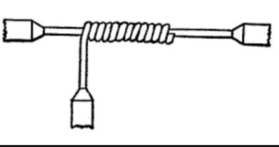
- Clean and strip the through piece for atleast 3.7mm in the center.
- Clean and strip one end of the T-piece for atleast 220mm.
- Twist strand through piece and first 6mm of T-piece.
- Untwist remainder of T-piece strands and straighten.
- Placing T-piece at right angle to center of the piece, tightly bind T-piece strands round the through piece against the lay of the cable one at a time, four strands round left-hand half through piece and three strands round right-hand.
- Cut-off surplus and smoothen over with pliers.
- Solder joined end.
- Ask the workshop technician to check your work.
STRAIGHT TWIST JOINT
PROCEDURE
- Strip clean and tin over a distance of 3mm.
- Lay the wire together to about 2mm.
- Twist tightly, pound the end to opposite direction. Each of the wire fitting closely up to the next.
- Solder the joined end.
- Ask the workshop technician to check your work.
TEE TWIST JOINT
- The wire is bated, cleaned and tinned for a distance of 2mm.
- Do not cut the wire.
- Tightly round the wire.
- Solder half of the joint to allow flexibility when insulating.
- Ask the workshop technician to check your work.
WIRING SYSTEM
This is responsible for powering specific element within a system that need electricity to work.
1. Surface wiring: This is a system of channel and boxes that let you put outlet switches or light fixtures anywhere you want, without the hassle of cutting into walls, fittings wire and pinching holes.
2. Conduit wiring: This is a tube used to protect and house electrical wiring in a building or structure. It may be made of metal, plastic, fibre or fitted clay. Most conduit are rigid but there are some flexible conduit too.
TYPES OF FLEXIBLE CABLE
- Surface conduit wiring
- Concealed conduit wiring
1. SURFACE CONDUIT WIRING: This system is suitable for low and medium voltage wiring installation VIR or PVC. Cables are run in meter pipes known as conduit which provide good mechanical protection to the installation of cable and reduce the risk of fire. The cables are drawn through the conduit by means of steel known as ‘fishing wire’ conduit pipe are available in various sizes which varies from 12mm-15mm in long tuning of pipes. The junction box are provided at a sufficient distance to facilitate the drawing of wires.
2. CONCEALED CONDUIT WIRING: The wiring is also called recessed wiring and coupled with all requirements or surface conduit wiring. In this system small channels are formed in the wall ceiling e.t.c when the building is under-construction, the conduit wiring are erected in those channels by strapples or saddles not more than (60cm) 2 inches. Inspection type conduit accessories like inspection type conduit, tee, elbow or junction boxes are fitted or mounted on the wall, at a specific distance during the installation of the conduit to facilitate drawing or removal of wire after the erection of the conduit pipe in the channel. They are closed and the wall are flushed off, of all electrical installation. Accessories are fixed on an insulating sheath which is fixed on cast iron boxes. This system requires good and continuous earthing and therefore it must be connected to the earth of the point entry of supply cables. The system is very costly and offers good mechanical protection. This system is generally used in industrial workshop, public building e.t.c The life of this system is approximately 40 years.
ADVANTAGES OF CONDUIT PIPE SYSTEM
- The mechanical protection for the insulation of the conductor is very good.
- The gives very good protection against fire due to short circuit.
- It provides protection against moisture in the earth.
- Damage cable can be easily replace in the building.
- It has a very neat and attractive appearance.
DISADVANTAGE OF CONDUIT PIPE SYSTEM
- The initial cost is very high.
- Danger of burns due to poor workmanship causes the insulation of the cable to damage.
- In damp condition, the moisture condenses inside the conduit pipe and does reduce the insulation resistance which may cause a short circuit between the cable thread and enters bore where it is fixed to the box with the lock nut.
CONDUIT BUSHING

Conduit bushing are used when the rigid conduit is not threaded. It is either made of available thin air formed a short steel. The bushing serves double purpose. Firstly, it prevents the insulation on the sheath edge of the conduit when they are pulled. It helps in securing the rigid conduit to conduct boxes when o lock is placed on the inside of a box. There is another close type of bushing which is used during construction of a building.
Types of bushing is provided with a cap as shown in the diagram below. The cap prevent moisture from entering the conduit system during construction.
LOCK NUT
When the conduit enter a box, it is necessary that the lock nut should be screwed on the conduit connection to the rigid box and the electrician continue. The lockout are pushed ontop the sheet steel. The lockout are hexagonal or octagonal.
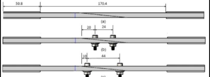
CONDUIT NIPPLES
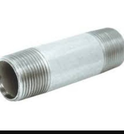
The nipple serve the same purpose as the conduit bushing. Similar to the bushing it has a smooth inner surface and they are used for providing a coupling to the conduit box. The nipples are rarely provided because the system cost less.
WIRING SYSTEM
There are two types of wiring system;
- Radial wiring system
- Ring wiring system
- RADIAL WIRING SYSTEM: In radial wiring system, wires are looped from the voltage sources to one socket and the other socket in the same like manner. If there is a cut along the wire, current stops to flow along the circuit, hence there is discontinuity in the flow of current in the circuit which is a major drawback of radial wiring system.
- RING WIRING SYSTEM: In this circuit, distribution point are connected to the main supply in a continuous closed circuit to rewire your house, make sure you’re using the correct wire for each ring circuit such as light, socket, shower and cooker