
Electrical and electronic symbols are simplified drawings that represent components, connections, or functions in a circuit. They let engineers, technicians, and students describe a circuit clearly without drawing each component as it looks in real life.
Symbols are used in circuit schematics, wiring diagrams, and technical documents. Many are standardized, but conventions can vary by region, industry, or drawing type. When a diagram includes a legend, follow it.
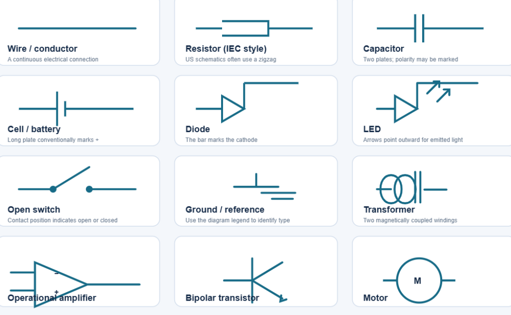
Why symbols matter
A schematic shows how a circuit works by representing components and their electrical connections. A symbol can identify a resistor, diode, switch, power source, or other device. Lines show conductors, while labels and reference designators identify particular parts.
The International Electrotechnical Commission’s IEC 60617 database contains standardized graphical symbols for electrotechnical diagrams. In the United States, IEEE/ANSI 315 covers symbols for electrical and electronics diagrams. Some familiar symbols differ between conventions. For example, a resistor may be drawn as a rectangle in IEC-style diagrams or as a zigzag in many US schematics.
Common schematic symbols
The descriptions below identify the usual shape or marking. Exact drawings can vary with the standard and diagram type.
| Component or function | What to look for | What it represents |
|---|---|---|
| Wire | A straight line | An electrical connection between points |
| Connected junction | Wires meeting, often with a dot | Conductors electrically connected |
| Crossing wires | Crossing lines, sometimes with a bridge or no dot | May indicate wires that are not connected; check the drawing convention |
| Ground or 0 V | One or more horizontal lines, or another ground marker | A circuit reference point; protective earth has a distinct symbol |
| Cell or battery | One or more pairs of long and short parallel lines | A DC source; the longer line conventionally marks the positive terminal |
| AC source | A circle with a sine-wave mark, or an AC label | An alternating-voltage source |
| Resistor | Rectangle or zigzag line | Limits current or creates a voltage drop |
| Variable resistor | Resistor symbol with an arrow | Adjustable resistance |
| Potentiometer | Resistor symbol with an arrow or wiper connection | Adjustable three-terminal voltage divider |
| Capacitor | Two parallel plates | Stores charge; a polarized type may include a “+” mark |
| Inductor | A coil or series of curved loops | Stores energy in a magnetic field |
| Transformer | Two coil symbols, often with core lines between them | Transfers AC energy between windings |
| Fuse | A small box, line, or fuse-specific mark in the conductor | Opens the circuit if current exceeds its rating |
| Switch | A break in a line with a movable contact | Opens or closes a circuit path |
| Diode | A diode mark with a bar at the cathode | Allows current primarily in one direction |
| Zener diode | Diode symbol with a modified cathode line | Provides voltage regulation or clamping in suitable circuits |
| LED | Diode symbol with arrows pointing outward | Emits light when forward current flows |
| Photodiode | Diode symbol with arrows pointing inward | Responds to incident light |
| BJT transistor | Three terminals, with an arrow on the emitter | A bipolar transistor; the arrow distinguishes NPN and PNP types |
| JFET or MOSFET | Three or more terminals with gate and channel markings | A field-effect transistor |
| Integrated circuit | A rectangle with labeled pins | A device containing multiple circuit elements |
| Relay | Coil symbol linked to switch contacts | An electrically operated switch |
| Ammeter | Circle marked “A” | Measures current; connected in series |
| Voltmeter | Circle marked “V” | Measures voltage; connected across two points |
| Operational amplifier | Triangle with “+” and “−” inputs | Amplifies the difference between its input voltages |
| Motor | Circle marked “M” or motor-specific symbol | Converts electrical energy into mechanical motion |
| Lamp or bulb | Circle with a cross or lamp mark | Converts electrical energy into light |
| Microphone or speaker | Audio-specific symbol | Converts sound to an electrical signal or vice versa |
The IEC symbol library includes categories for conductors, passive components, semiconductors, power conversion, protective devices, measuring instruments, and more. See the official IEC 60617 overview.
Active and passive components
Schematics include both passive and active components:
- Passive components, such as resistors, capacitors, and inductors, store or dissipate energy.
- Active components, such as transistors and integrated circuits, can control or amplify signals and often require a power supply.
This is a useful introductory distinction, though exact definitions can depend on the context.
How to read symbols in a schematic
- Find the power and ground connections. These show how the circuit is supplied and which point serves as its reference.
- Trace the wires. Lines and junctions indicate electrical connections. A crossing without a junction mark may mean the wires are separate.
- Identify each component. Look at its symbol, labels, and reference designator. Common designators include R for resistor, C for capacitor, and D for diode, though conventions vary.
- Check polarity and direction. Batteries, polarized capacitors, diodes, and transistors may need to be connected in a particular orientation.
- Read the legend and notes. They can explain drawing-specific symbols, abbreviations, and connection rules.
A schematic is not necessarily laid out to match the physical positions of its parts. Its purpose is to show electrical relationships and signal flow.
Common symbol differences
Some schematic symbols have more than one widely used form. Resistors are a common example: IEC drawings often use a rectangle, while many US drawings use a zigzag. Switches, ground markers, and some power-source symbols can also vary.
Standards help make drawings consistent, but no single small reference table covers every symbol used in electrical, electronic, industrial, and building diagrams. For professional work, use the governing standard and the diagram’s legend.
Key points
Electrical symbols are a compact visual language for showing circuit components and connections. Learn the common symbols, check junctions and polarity carefully, and use the diagram’s legend when a mark is unfamiliar. For standardized references, consult IEC 60617 or IEEE/ANSI 315.