
TECHNICAL REPORT
ON
STUDENT INDUSTRIAL WORK EXPERIENCE SCHEME (SIWES)
AT
TRANSMISSION COMPANY OF NIGERIA (TCN) PAPALANTO SUB REGION, OLORUNSOGO, OTTA, OGUN STATE
BETWEEN 2nd DECEMBER, 2019 TO 28th MARCH, 2020
BY
OJO EMMANUEL IBUKUNOLUWA 2018232040045
SUBMITTED TO THE DEPARTMENT OF ELECTRICAL ENGINEERING IN PARTIAL FULFILLMENT OF THE REQUIREMENT FOR THE AWARD OF NATIONAL DIPLOMAT IN ELECTRICAL ENGINEERING OF THE POLYTECHNIC, IBADAN.
ABSTRACT
DECLARATION
MR. M. T. FOLAMI
ACKNOWLEDGEMENT
DEDICATION
I dedicate this report to my father for his support both financially and mental encouragement and also finding me the IT placement for my SIWES.
TABLE OF CONTENT
Declaration ii
Acknowledgement iii
Dedication iv
CHAPTER ONE: SIWES
Introduction 8
History of SIWES 8
Objectives and aims of SIWES in Nigeria 8
Importance of SIWES 9
CHAPTER TWO: THE TRANSMISSION COMPANY OF NIGERIA (TCN)
2.1. The power system grid in Nigeria 10
2.2. History of Transmission Company of Nigeria 11
2.2.1. Vision and Mission 12
2.2.2. Scope of their activities 12
2.3. Organization structure of the Transmission Company of Nigeria 13
2.4. The department at the transmission of Nigeria, TCN, Papalanto Works centre and their functions 14
CHAPTER THREE: THE WORK DONE AND EXPERIENCE GAINED
3.1. Introduction 16
3.2. The lines maintenance department, LMD. 16
3.2.1. The work done and experience gained in LMD 17
3.2.1.1. The transmission tower line inspection 17
3.2.1.2. The replacement of the yellow phase conductor linking the line isolator and the line circuit breaker 17
3.2.1.3. Replacement of the 330kV transmission tower glass disk insulation to a silicon composite insulator 18
3.3. The Electrical maintenance department, EMD 20
3.3.1. The work done and experience gained 20
3.3.1.1. Topping of the insulation oil of the line current transformer 20
3.3.1.2. Refilling of the SF6 in a circuit breaker 22
3.3.1.3. Conduction of annual preventive maintenance 24
3.3.1.4. Illumination of the Olorunsogo 330kV switchyard 24
3.3.1.5. Repairs of the yellow phase line current transformer oil leakage 24
3.3.1.6. Repairs of the bus isolator broken finger socket 25
3.3.1.7. Lubrication of the stiffed movable parts 25
3.4. The Protection, Control & Metering department 26
3.4.1. Work done under the protection, control & metering department 26
3.4.1.1. The energy reading for the end of the month 26
3.4.1.2. Annual preventive maintenance of a circuit breaker 27
3.4.1.3. Maintenance of the circuit breaker 28
3.4.1.3.1. The replacement of burnt closing coil in the circuit breaker 28
3.4.1.3.2. the failure of the hydraulic oil pump motor to actuate due to defective motor relay contactor 29
3.4.1.3.3. The failure of a circuit breaker to close 29
3.4.1.3. The design of a protection wiring scheme modification 30
3.4.1.4. Rearrangement of the wiring system of a circuit breaker 30
3.4.1.5. Installation and commissioning of a transformer 31
3.4.2. Experience gained under the department 32
3.5. The system operations department 33
3.5.1. Work done under the system operation department 33
3.5.2. Work experience gained 34
3.5.3. Equipment and materials used in the system operation department 34
CHAPTER FOUR: IMPORTANT ELECTRICAL EQUIPMENTS USED IN THE PAPALANTO WORKS CENTRE, TRANSMISSION COMPANY OF NIGERIA.
4.1. Introduction 40
4.2. The functions and usage of the electrical equipment 40
CHAPTER FIVE: CONCLUSION, PROBLEM ENCOUNTERED AND RECOMMENDATION
5.1. Conclusion 50
5.2. Problem encountered during the SIWES training. 50
5.3. Recommendations and suggestions 50
CHAPTER ONE
THE STUDENT INDUSTRIAL WORK EXPERIENCE SCHEME (SIWES)
1.1 INTRODUCTION
The Student Industrial Work Experience Scheme (SIWES), also known as Industrial Training (IT) is a compulsory skills training program designed to expose and prepare students of the Nigerian universities, polytechnics, colleges of education, colleges of technology and colleges of agriculture for the industrial work situation they are likely to meet after graduation.
The scheme also afford students the opportunity of familiarizing and exposing themselves to the needed experience in handling equipment and machinery that are usually not available in their institutions. Before the establishment of the scheme, there was a growing need or concern among industrialists, that graduates of institutions of higher learning lacked adequate practical background studies preparatory for employment in industries. Therefore, employers were of the opinion that the theoretical education in higher institutions was not responsive to the needs of the employers of labor.
1.1.1 HISTORY OF THE STUDENT INDUSTRIAL WORK EXPERIENCE SCHEME (SIWES)
The introduction, initiation and design of the SIWES were done by the Industrial Training Fund (ITF) in 1973, to acquaint students with the skills of handling employers equipment and machinery. It was solely funded by the Industrial Training Fund (ITF) during its formative years. However, due to financial constraints, the fund withdrew from the scheme in 1978.
The federal government noting the significance of the skills training which the SIWES is, handed the management of the scheme to both the National Universities Commission (NUC) and the National Board for Technical Education (NBTE) in 1979. The management and implementation of the scheme was however reverted to the Industrial Training Fund (ITF) by the Federal government in November, 1984 and the administration was effectively taken over by the Industrial Training Fund (ITF) in July, 1985, with funding solely borne by the Federal Government
1.2. OBJECTIVES AND AIMS OF SIWES IN NIGERIA
Arising from the need of founding the organization or scheme, its (SIWES) objectives as an organization are as listed below:
Exposing students to the work method and techniques in handling equipment and machinery that may not be available in their institutions.
Providing an avenue for students in institutions of higher learning to acquire Industrial skills and experience in their course of study, which are restricted to Engineering and Technology including Environmental studies and other courses that may be approved courses of NCE (Technical), NCE (Agricultural), NCE (Business), NCE (Fine and Applied Arts) and NCE (Home Economics) in colleges of Education are also included.
It provides students with an opportunity to apply their knowledge in real work situation thereby bridging the gap between theory and practice
Preparing the students for the industrial work situation they are likely to meet after their graduation.
Making the transition from school to the world of work easier and enhance students contact for later job placement.
Enlisting and strengthening of employers involvement in the entire educational process and prepare students for employment after graduation.
Provide students the opportunity to develop attitudes conducive to effective interpersonal relationships towards the job.
Ernest placement and strengthen employees involvement in the educational process of preparing students for employment in industries.
1.3. IMPORTANCE OF SIWES
It exposes students to more practical work methods and techniques.
It also prepares the students for the labor market after graduation.
It provides students with an opportunity to apply their theoretical knowledge in real life situations.
It strengthens links between the employers, universities and Industrial Training Fund (ITF).
CHAPTER TWO
THE TRANSMISSION COMPANY OF NIGERIA (TCN)
.1 THE POWER SYSTEM GRID IN NIGERIA
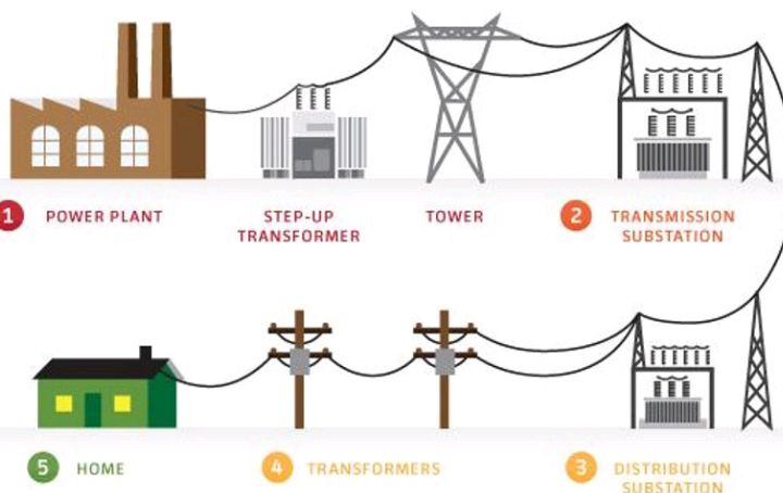
Electrical energy has a lot of importance all-over the world and therefore being used for different purposes in complexity or simplicity either for industrial purposes or for the satisfaction of the end user. We would have noticed that, the moment we switch on our electrical appliances at home, it works once there is electricity. Well, have you ever wondered how the electricity got to the appliance fast? This involves a very technical and systematic process on making the electricity available for our maximum usage.
Therefore, making this electrical power or energy circulate throughout the Nation (Nigeria), the process involves three (3) stages, which are the generation sector of the energy, the transmission of this energy and finally the distribution of the energy through a systematically arranged grid known as the National Grid.
THE GENERATION SECTOR (GENERATION STATIONS) IN NIGERIA
In Nigeria, a total number of twenty-three (23) generating power plants are available with the capacity to generate 11,165.4 MW of electricity in Nigeria. The energy are mostly generated through thermal and hydropower sources which comes from fossil fuels especially gases which accounts for eighty-six percent (86%) of the capacity in Nigeria with the remainder gotten from hydropower.
These sources of energy are used to set the turbine engine in motion to produce an induced electromotive force (voltage) ranging from 10-16kV. The Transmission Company of Nigeria (TCN), Papalanto Works Centre where I did my Industrial Training (IT) was linked with a generating station which has two (2) phases; Phase 1 having 8 generators (Gas Turbine Generator, GTG) and 4 transformers (Gas Main Transformers, GMT) with 2 generators serving a transformer each. The generators generate a voltage of 10kV before the transformer of 105MVA capacity is used to step it up to 330kV. Meanwhile, the Phase 2 has 6 generators (4 Gas Turbine Generators, GTG and 2 Steam Turbine Generators, STG) and 7 transformers (4 Gas Main Transformers, GMT and 3 Steam Main Transformers, SMT) but a transformer is inactive. The GTG generates 10kV each and the STG generates 16kV each and transferred into a step-up transformer of 150MVA capacity before it’s step-up to 330kV.
The Transformers have their primaries to be 10/16kV and their secondaries to be 330kV being a step-up transformer. It is generated at this high voltage to reduce power loss over a long distance along the transmission lines (conductors) which are connected to the National Grid from all generation stations in Nigeria for transmitting.
B. THE TRANSMISSION SECTOR IN NIGERIA
This is the next phase of getting the energy to the consumers, the transmission sector serves as an intermediary of the voltages transferred from the generation sector to the distribution sector, standing as an interface between them (generation and distribution).
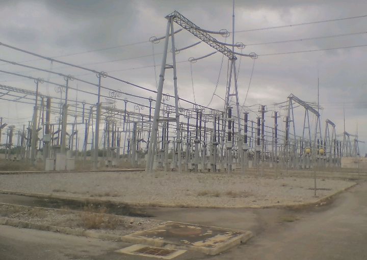
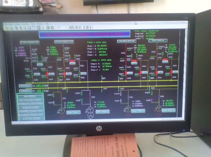
THE OLORUNSOGO 330kV TRANSMISSION STATION PHASE 1 SWITCHYARD
This process starts by the transmission sector receiving High Voltage Alternating Current (HVAC) of 330kV from the generation and transporting it through transmission lines (conductors) to another transmission sub-station to step-down to 132kV by a transformer and further transmission to a sub-station to step-down to 33kV for transmitting it to a distribution substation or injection sub-station.
C. DISTRIBUTION SECTOR IN NIGERIA
This is the last stage of electricity before it gets to the consumers, they accept voltage at 33kV and step it down with the aid of distribution Transformers to 11kV which is in turn stepped down to 0.415kV and transferred through a low tension pole line phase (Red, Yellow, Blue and Neutral) which it is then tapped from any of the 3 phases and a Neutral to give the 240V (household voltage appliance).
The household voltage formula relationship:
Line voltage: VAB, V AC, VCA
Line voltage = √3 Phase voltage
Vpn = 415 / √3
2.2. HISTORY OF THE TRANSMISSION COMPANY OF NIGERIA (TCN)
The Transmission Company of Nigeria (TCN) manages the electricity transmission network in the country; the Transmission Company of Nigeria (TCN) emerged from the former National Electric Power Authority (NEPA) now known as the Power Holding Company of Nigeria (PHCN).
It was brought about due to the fusion or merger of the Transmission and Operations sectors on April 1, 2004 and it was incorporated in November, 2005. It is one of the unbundled business units under the Power Holding Company of Nigeria (PHCN), the company was licensed a transmission license on the 1 July, 2006 and another on the 10 June, 2013 for electricity transmission and system operations.
The Transmission Company of Nigeria (TCN) licensed activities includes electricity transmission, system operations and electricity trading. It comprises of 9 transmission Regions: Bauchi, Benin, Enugu, Kaduna, Kwara, Lagos, Osogbo, Port-Harcourt and Shiroro and a National Control Centre (NCC) at Osogbo with 3 Regional Control Centre (RCC) at Benin, Kaduna and Lagos.
It is responsible for evacuation electric power generated by the electricity Generating Companies (GenCos) and wheeling it to the Distribution Companies (DisCos). It provides the vital transmission infrastructure between the GenCos and the DisCos Feeder Sub-station.
2.2.1. VISION AND MISSION
The Company’s vision is to be “one of the leading electricity transmission company in the world with a solid reputation for delivering reliable, cost-effective electric power to the end users in Nigeria and in West-Africa sub-station.
It’s mission is to “cost-effective build, plan, provide operate and maintain the required assets, equipment along with a reliable and efficient transmission Grid network for evacuating and dispatching high quality electricity with minimal losses.
2.2.2. SCOPE OF THEIR ACTIVITIES
The activities being carried out by the Transmission Company of Nigeria (TCN) revolves around the electricity transmission, system operations and electricity trading which are being carried out by the Transmission Service Provider (TSP), System Operations (SO) and Market Operations (MO) by collecting the electricity generated and wheeling it to the distribution company.
The Transmission Service Provider, TSP:
They oversee the development and maintenance of the transmission infrastructure. It is responsible for the National inner-connected transmission system of sub-stations and power lines and providing open access transmission services. It’s role is to maintain the physical infrastructure that make up the transmission Grid and expand it to new areas.
The System Operations, SO:
The SO manages the flow of electricity throughout the power system from generation to distribution companies. It operates the Grid Code for the Nigerian Electricity Supply Industries (NESI). The SO has the responsibility for ensuring that the Transmission Grid lines are reliable and maintaining the technical stability of the Grid through its operations of planning, dispatch and control of the electricity on the Grid.
The Market Operations, MO:
The MO administers the Market rules of the Nigerian Electricity Supply Industries, NESI. It is responsible for the administration of the Electricity Market and promoting efficiency in the market.
The Transmission Company of Nigeria, TCN, activities are generally based on;
Operate; expand/upgrade transmission facilities for efficient and effective wheeling of generated electricity.
Build a Transmission Grid that can efficiently evacuate all generated power.
Create adequate network redundancies to ensure at least 99.9% reliability.
Reduce transmission losses to less than 5%.
Pursue inter-connection with neighboring countries for power exchange with associated cost savings from the sharing of reserve capacity and energy resources.
Provide an effective project management system.
Provide standard human capacity development of the Transmission Company of Nigeria staff for high level performance.
Standardization of procurement procedure to reflect international standard.
Ensuring that safety and environmental issues are managed to meet international standards.
Improve the TCN’s revenue base to ensure a self-sufficient and self-sustaining company.
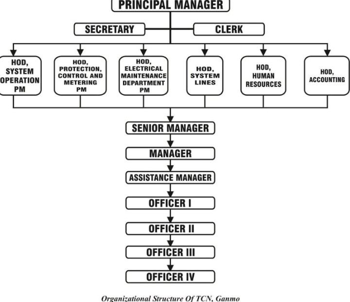
2.3. ORGANIZATION STRUCTURE OF THE TRANSMISSION COMPANY OF NIGERIA
The Organizational Structure of the TCN, Papalanto Works Centre
2.4. THE DEPARTMENTS AT THE TRANSMISSION COMPANY OF NIGERIA, TCN PAPALANTO WORKS CENTRE AND THEIR FUNCTIONS
The Transmission Company of Nigeria, TCN, Papalanto Works Centre is divided into units of various departments which are 8 in numbers, namely;
Human Resources department
Accounting department
Protection, Control and Metering department
Electrical Maintenance department
System Lines Maintenance department
System Operation department
Drivers department
Stores department
HUMAN RESOURCES DEPARTMENT:
It has an acronym “HR”. They provide essential administrative support to the executives and departmental managers (HODs) of the Transmission Company of Nigeria (TCN), Papalanto Works Centre and Olorunsogo as its Area Control Centre (ACC). The human resources department is able to assist with both complex and general administrative duties with their communication and data entry skills creating more time to carry out managerial tasks by the supervisors.
This department is responsible for the data processing, file maintenance, communication and clerical management functions of the Transmission Company of Nigeria (TCN), Papalanto Works Centre.
ACCOUNTING DEPARTMENT:
The primary purpose of every accounting department is the keeping of the ongoing financial record keeping. The account department base on the monetary information (operational expenses, salaries, donations, capital expenditures, investments, cash-flow, and utilities) which are all tracked or recorded on a monthly basis at a minimum.
The financial history of Transmission Company of Nigeria (TCN), Papalanto Works Centre are being created by this department which can be used in different ways as it gives the management of the firm the financial health and wealth status of the firm at any given time.
PROTECTION, CONTROL AND METERING DEPARTMENT:
Being referred to as PC&M( acronym), they can be termed as the life of the electrical and electronics equipments as they are responsible for ensuring correct and efficient protection of the various electrical equipment and devices in the transmission station. They also deal with the wiring protection or configuration of the electronic equipment(relays, circuit breakers) of the Transmission Company of Nigeria(TCN), Papalanto Works Centre in Olorunsogo station and the four(4) other substations under its jurisdiction.
They solely deal with the maintenance, protection and configurations of these equipment in the transmission station under their Area Control Centre (ACC). The department is also responsible for installation, commissioning and decommissioning, maintaining, troubleshooting and repairing of the critical systems used for detecting and responding to power system faults, controlling system devices and Metering schemes throughout the entire transmission Grid under its Area Control Centre.
ELECTRICAL MAINTENANCE DEPARTMENT:
This department carries out both preventive and corrective maintenance as well as being responsible for installation, commissioning and decommissioning, troubleshooting, maintaining the equipments along with the Protection, Control and Metering( PC&M) crew as it involves the Protection of these equipments.
SYSTEM LINES MAINTENANCE DEPARTMENT:
This department are responsible for the maintenance of the transmission lines in any form to avoid tripping on earth fault from the feeder’s relay, maintenance of the transmission lines towers which involves cutting of elongated trees that are surrounding and in between the transmission towers that can cause disturbance or resistance in the sense of tripping caused by earth fault and bush burning respectively.
The department is also responsible for the safety and maintenance of conductor lines in the switchyard grid throughout the stations under it’s ACC.
SYSTEM OPERATIONS DEPARTMENT:
The System Operations termed SO, which the workers can also be referred to as the Independent System Operators(ISO) are responsible for the management of the flow of electricity throughout the power system grid coming from the generation and going to the distribution end before getting to their respective end users. They are also responsible for ensuring that the transmission grid lines are reliable(they are maintaining their technical stability) through its operations by planning, dispatching and controlling of the Electricity flow on the Grid.
The Independent System Operators(ISO) monitors the functionality status by monitoring and operations of the whole system of the Transmission Company of Nigeria(TCN), Papalanto Works Centre before calling on the maintenance crews if a problem persists as well as the National Control Centre NCC. There operations involves the Generation Companies(GenCos) and the Distribution Companies(DisCos) in terms of load management(the quantity of electricity to be supplied and the quantity o the electricity needed respectively) and the enforcement of the Grid discipline.
DRIVERS DEPARTMENT:
The drivers department are responsible for the transportation of the maintenance crews(field workers) to any expected destination where there is a fault to be corrected. The drivers HOD I.e Head of Department is to direct, choose and issue the transportation fees in terms of petrol purchasing to a driver for transporting the crew to the point of work.
STORES DEPARTMENT:
This department is in charge of the safekeeping of all the electrical and electronic equipments to be used or to be repaired by the work centre in any necessary case. These equipments can be line Current Transformer(CT), line Voltage Transformer(VT), line Power Transformer(PT), Relay Sensors, Contactor motor, so on and so forth.
CHAPTER THREE
THE WORK DONE AND EXPERIENCE GAINED
3.1. INTRODUCTION
This chapter contains the discussion of the work done and the experience gained during my four (4) months Industrial Training course which includes every training in each of the department visited or attached. The first most important experience gained is the importance and the very significance of safety because any single mistake made at switch yard will leads to instant death by electrocution, there is no second chance of mistake at the Transmission Company of Nigeria, TCN, because of the High Voltage Alternating Current, HVAC, the company is dealing with. Therefore, many emphasis and precautions were always taken before entering the switch yard to perform any kind of work scheduled to be done even for inspection purposes.
Having said this, the first and very crucial procedure to take before starting any work in the switchyard is to; collect the work permit or work and test permit from the operator on duty.
Have the operator open the isolator or the disconnected on both sides and finally.
Ensure that the operator on duty guarantees that the electrical equipments are safe to be worked on before proceeding with the work.
It is necessary for the maintenance crew to apply the ground wire so as to discharge(Earth) the electrical equipment of any residual charge, this is done to prevent electrocution of the maintenance crew by the residual charge inthe equipment.
Safety is very crucial to this job therefore it’s advisable that the maintenance crew are putting on there safety materials like the safety boots, hard hats (helmet) and so on. The scope of work done and experience gained will be analyzed below on each of the department visited in their order of visitation. During the period of four 4 months being spent under the supervision of the various head of department(s) HODs of the various departments I was posted to which are of namely, the Lines Maintenance Department (LMD), the Electrical Maintenance Department (EMD), the Protection, Control and Metering Department (PC&M) and the System Operation (SO).
3.2. THE LINES MAINTENANCE DEPARTMENT, LMD
The period spent in this department was a total of four, 4 weeks (2nd December to 27th December, 2019). This department which is being lead by Engr. Oyetunde as the senior manager and the HOD of the department. The line maintenance department is responsible for the maintenance of the transmission line conductors in and out of the switchyard. Their activities evolves around carrying out of the preventive maintenance and corrective maintenance of the transmission line conductors in and out of the switchyard.
PREVENTIVE MAINTENANCE: These are the maintenance done according to the name to prevent and unforseen faults tripping of the relays on the transmission line conductors. Examples of the preventive maintenance is the Inspection of the transmission towers and line tracing, the Inspection of the transmission towers Insulators (Glass disk Insulators) and the cutting of crippling plants around the transmission towers.
CORRECTIVE MAINTENANCE: These are the maintenance done for the actual repair of already existing faults on the transmission line conductors inside or outside the switchyard. Examples are the replacement of broken or melted conductors in the switchyard and the changing of the glass disk Insulators to the silicon composite Insulators.
3.2.1. THE WORK DONE AND EXPERIENCE GAINED IN LMD TCN, PAPALANTO
The scope and procedure of the works done as well as the experience gained after the work was done are going to be listed below. They are as follow;
Transmission tower lines inspection.
Replacement of the Yellow Phase conductor linking the bus isolator and the line breaker.
Replacement of the 330kV tower glass disk Insulators to a silicon composite Insulator.
3.2.1.1. THE TRANSMISSION TOWER LINE INSPECTION
The scope behind the inspection done on the transmission towers involves line tracing (it is the term used in transmission referring to the clearing of bushes or the cutting down of dangerously high trees beneath or close to the towers), cutting of cripplers ( plants that grows on the tower which tends to crawl up on the tower) and inspection of the glass disk Insulators in case of corrosion of the Insulator. These are the basis of preventive maintenance of the line maintenance department on the transmission towers.
EXPERIENCE GAINED
After undergoing the work process, I learned the following:
I can successfully locate a transmission tower number on the nameplate of the tower.
I understand the basics and importance of Line tracing.
The equipment used is the cutlass for cutting of the bushes around the towers.
3.2.1.2. THE REPLACEMENT OF THE YELLOW PHASE CONDUCTOR LINKING THE LINE ISOLATOR AND THE LINE CIRCUIT BREAKER
In the Papa 132/33kV transmission sub-station, the Yellow Phase conductor linking the isolator and line breaker was replaced due to its melting at isolator end of the conductor. The melting of the conductor (The Aluminum Conductor Steel Reinforced) was as a result of the heat generated in the conductor when High Voltage Alternating Current, HVAC, pass through it.
The equipments and materials required to carry out the job are:
Ground stick and ground wire.
Spanners and a pair of pliers.
The Aluminum Conductor Steel Reinforced cable.
Measuring tape.
Hacksaw
Bolt and nut.
PROCEDURES ON THE JOB:
Apply the ground wire using the ground stick in order to discharge the electrical equipment from any residual charges by connecting the ground wire at the end of the isolator and circuit breaker while tightening it to the earth wire around the equipment respectively.
Lose the conductor linking the isolator and the circuit breaker at both ends and also the existing cable key because the key has also melted alongside the conductor with the aid of a spanner and a pair of pliers.
Now, measure the length of the cable to be fixed with the aid of a measuring tape, but if a measuring tape is not available, the cables maybe placed beside each other leaving a little margin for mistake.
Mark the length out on the new cable, tightening of the conductor at both ends before cutting is necessary so as to avoid the scattering or misalignment of the cable from its original position before cutting with the aid of a Hacksaw.
Fix the one end of the cable into a cable key, we can always use a pair of pliers to the conductor end in order to fit into the cable key.
Connect the conductor end with the cable key on the isolator end and tighten the connection by using bolt and nut while the other end of the conductor is screwed to the circuit breaker.
EXPERIENCE GAINED
At the end of the job, I learnt the following;
The reason for using a copper cable key in the connection.
How to cut and fix a conductor into a cable key of its size.
How to successfully apply a ground wire using a grounding stick to an electrical equipment.

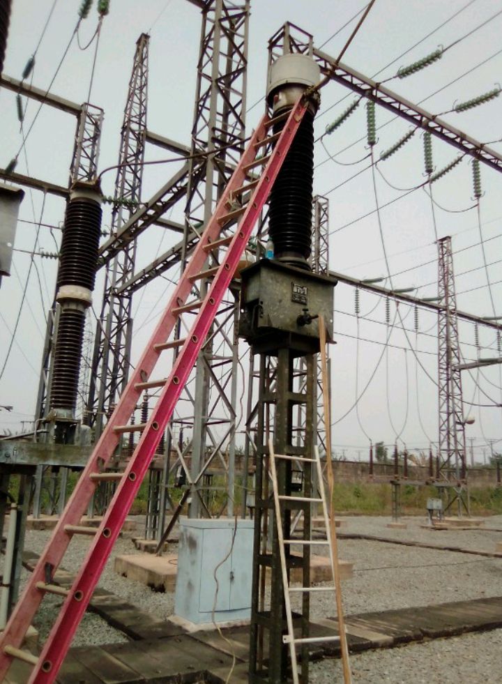
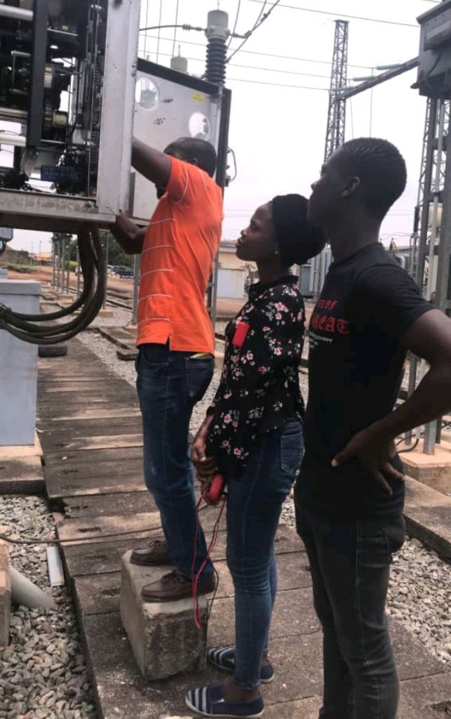
THE LINES MAINTENANCE CREW AT WORK
3.2.1.3. REPLACEMENT OF THE 330kV TRANSMISSION TOWER GLASS DISK INSULATORS TO A SILICON COMPOSITE INSULATOR
The type of transmission tower is determined mostly on the number of Insulators the transmission tower gantries or cross arms are carrying. For further explanation, the 330kV transmission towers carries a total of 18 or 20 Insulators on each gantry respectively, while the 132kV transmission towers carries a total of 11 or 10 Insulators on their gantries respectively and the 33kV transmission towers carries 3 each on their gantries.
The replacement of Olorunsogo Ayede 330kV transmission tower lines Insulator after Idi-aba, Abeokuta were replaced from the previous glass disk Insulators to a silicon composite Insulators.
The following apparatus or equipment are needed, they are;
The belts: These belts are being used by the climbers (the contract engineers that climbs the transmission tower), it enables them to hang up in the air while they work.
Cutlasses: They are used to cut down bushes and clippers surrounding the transmission tower so as to create space for the climbers to climb and other workers to stand and assist the work progress.
The grounding stick and ground wire: The grounding stick and ground wire are being used for discharging the skyline or the conductor on the gantries of the transmission tower by connecting the end of the ground wire to the skyline and the other end to the fastened to the transmission tower.
The hook ladder: The hook ladder is being hung on the gantry of the transmission tower, it is very useful in helping the climbers get closer to the conductors before getting on the conductor after grounding the conductor.
The High Line: These are much thicker ropes used for transferring virtually all of the equipments which range from the grounding stick and wire, the hook ladder, the composite Insulators, the conductor yoke and the pull lift to be used except from the G-shackle and wire spring from the ground to the tower climbers and from the tower gantries to the ground.
The Conductor Yoke: The conductor yoke is placed on the conductors of the tower gantry. It is used to suspend or tension the conductors before connecting it with the pull-lift.
The Pull-lift: The Pull-lift is used to jack up the conductor yoke to enable the proper tensioning of the conductors or skyline.
Procedures for the Job:
The bushes around the transmission tower is going to be cleared if there are any bushes around the tower with the aid of the cutlass.
As at the time of clearing the bushes, the climbers woube getting prepared by fastening their belts on them and the high line is then strapped to their belts while they climb the tower.
When the climbers get to the tower gantry they are to work on, the high line is then thrown down for knotting, after the knotting, the ground stick and ground wire is passed up to the climbers for the earthing of the skyline, the hook ladder is then passed up to them after the earthing is done.
The pull-lift and conductor yoke is knotted to the high line and transferred to the climbers, the conductor yoke is fitted to rest on the skyline while the pull-lift is hastened on the conductor yoke, when the pull-lift is being jacked it cause the tensioning of the skyline.
When the skyline is finally properly tensioned, the glass disk Insulator contract for its removal. During this process, the G-shackle and the wire spring should be prepared by fastening it to the bottom leg of the tower.
At this point the high line is hastened around the G-shackle and wire spring for the easy dropping of the glass disk Insulator. Also, the silicon composite Insulator is tightened to the high line to be transferred to the climbers. Then, as the glass disk Insulator is coming down, the silicon composite Insulator is going up to the climbers.
EXPERIENCE GAINED
The replacement of the Olorunsogo-Ayede 330kV transmission tower glass disk Insulators to silicon composite Insulators was indeed the best experience I had, I also learnt a lot during the course of the job which were very important and crucial points to observe, and they are as listed below;
I learnt how to differentiate between transmission towers of different voltage ratings.
I learnt how to knot the equipments around the high line to be transferred to the climbers.
I also learnt how to separate the glass disk Insulators into smaller pieces.
I was lectured over the advantages of the silicon composite Insulators over the glass disk Insulators which are the glass disk Insulators gets corroded and break off which can cause the cutting or tripping of the skyline when it breaks, the advantage that the silicon composite Insulators do not rust during the harmattan season while the glass disk Insulators do and finally for the that the silicon composite Insulators are more durable, weighs less when compared to the glass disk insulators and the silicon composite Insulators last longer than that of the glass disk Insulators in terms of their respective expiry dates.
3.3. THE ELECTRICAL MAINTENANCE DEPARTMENT, EMD
After finishing my schedule with the line maintenance department, LMD I waposted to the Electrical Maintenance Department, EMD, where I spent another five(5) weeks (30th December, 2019 to the 31st January, 2020). The department is lead by Engr. Babatunde as the senior manager of the department and the HOD. This department is responsible for the maintenance and repair of all the Electrical equipments in the switchyard of the area control center and the other sub-station under its jurisdiction.
The scope of activities done in this department are preventive maintenance and corrective maintenance.
PREVENTIVE MAINTENANCE in the sense that Preventive maintenance are procedures carried out on the equipment to ensure proper functioning of the equipments and avoid any unforeseen faults or breakdown. For example: refilling of the gas in the circuit breaker, the annual preventive maintenance (APM), topping of the insulation oil of the current transformer, lubrication of the movable parts of a line isolator and bus isolator et cetera.
CORRECTIVE MAINTENANCE is a type of maintenance that is carried out to correct or repair any existing faults in the switchyard. For example: the repair of the Yellow Phase oil leakage, repair of the bus isolator broken finger, illumination (fixing of new lighting bulbs).
3.3.1. THE WORK DONE AND EXPERIENCE GAINED
Under the five 5 weeks program spent in this department, I participated in the following jobs listed below:
Topping of the insulation oil of the line current transformer, CT.
Refilling of the Sulphur hexafluoride gas, SF6 gas, in the circuit breaker, CB.
The conduction of the Annual Preventive Maintenance, APM.
Illumination of the switchyard.
The repair of the Yellow Phase current transformer oil leakage.
The repairs of the bus isolator broken finger.
Lubrication of the stiffed movable parts of the Line isolator and the bus isolator.
3.3.1.1. Topping of the insulation oil of the line current transformer
The line current transformer, CT, can be simply defined as an electrical equipment used to measure or determine the total amount of current flowing in the power system circuit. It also serves as a relay protection, in the sense that it assist the relay panel in the detection of over current, short circuit and earth fault as the current transformer helps to measure the current in the power system circuit. Therefore, any current above the rated current would send a signal to the relay panel causing the relay to trip.
There are four, 4, types of current transformer which are the Window type, Bushing type, the Bar type and the Wound type of current transformer(s). The type of current transformer used in the transmission station grid is the Bushing current transformer which are specifically constructed to fit around a bushing. They are also mounted in a transformer or a circuit breaker mostly used for current greater than 100A.
The insulating oil used to fill up the current Transformers are often called transformer oil, which are mainly mineral oil. There are different colors of a transformer oil, they include; Silver, Gold and plain color et cetera. The functions of a transformer oil is as follows;
Cooling of the transformer because the current transformer carries a lot of current due to the amount of power flowing through it, then heat would be generated.
The oil serve as an insulation medium for the current transformer for preventing the injected current from getting to the body of the current transformer so as to avoid electrocution of the maintenance workers.
The insulation oil also helps suppress corona discharge and arcing in the transformer.
The apparatus or tools needed to complete the job above are as follows:
Ground stick and ground wire
Manual hand pump and hose
Spanners
Ladder and an iron gasket.
Procedures on the Job
Open the bus isolator on both ends before applying the temporary ground to the Electrical equipment.
Fix the iron gasket to the hose and then tighten it to the current transformer oil tap with the manual hand pump placed inside the transformer oil container.
After this open the current transformer oil valve while pumping the transformer oil into the current transformer by turning the manual hand pump handle in a clockwise direction.
Fill the current transformer to three-quarter of the current transformer oil gauge to avoid the bursting of the current transformer oil bulb.
Close the current transformer oil valve and withdraw the remaining transformer oil in the hose into the container by turning the manual hand pump handle in the anticlockwise direction to reduce oil spillage or wastage.
Finally, remove the temporary ground wire and close the bus isolator on both ends.
Experience Gained
At the Ota 132/33kV substation which the topping of the insulation oil was done, I gained the following experience:
- I learnt that before beginning any job in the switchyard, it is compulsory to collect the work or work and test permit and ensure the operator guarantees the electrical equipment is safe to work on.
- It is also important to apply the ground wire with the aid of a ground stick for proper earthing of the equipment.
- I learnt how to plan and improvise based on the job at hand before beginning.
- After the job, carry out the functionality and operational test.
THE EQUIPMENTS USED IN TOPPING THE LINE CURRENT TRANSFORMER
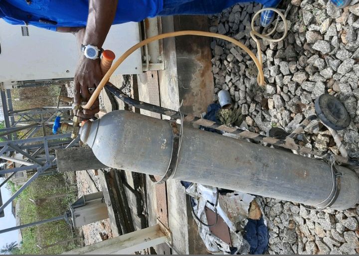
3.3.1.2. REFILLING OF THE SF6 GAS IN A CIRCUIT BREAKER
The circuit breaker is an electrical switching device which can be operated manually and automatically for controlling and protecting an electrical powered system. The circuit breaker is used for protecting or clearing any short circuit fault or any other type of electrical fault( such as electric cable faults), therefore residing to high fault current flowing through this equipment as well as the power network itself from damaging the equipment and the network permanently.
The Circuit breakers of the high voltage alternating current varies in the form of names from different producers, but they are similar in their performance either by their operating mechanism or their quenching mechanism.
In the sense of operating mechanism of Circuit breakers, it can be categorized into three, namely;
Spring operated circuit breaker
Pneumatic circuit breaker
Hydraulic circuit breaker.
It can also be categorized by its quenching mechanism, namely;
Oil circuit breaker.
Air circuit breaker.
Sulphur hexafluoride gas (SF6) circuit breaker.
Vacuum circuit breaker.
The job above is done in a spring charged circuit breaker by operation and the sulphur hexafluoride gas SF6 by quenching mechanism.
The function of the sulphur hexafluoride gas in the circuit breaker is used in the arc quenching medium of the circuit breaker as the sulphur hexafluoride gas is an electronegative gas and has a strong tendency to absorb free electrons. The sulphur hexafluoride gas is used in the circuit breaker because the contacts of the breaker are opened in a high-pressure flow of sulphur hexafluoride gas and an arc is struck between them.
The sulphur hexafluoride gas captures the conducting free electrons in the arc to form relatively immobile negative ions. This loss of conducting electrons in the arc quickly builds up enough insulation strength to extinguish the arc.
The apparatus used in this job are a gas hose return valve adaptor and the sulphur hexafluoride gas cylinder to fill the circuit breaker with.
Procedures for refilling the sulphur hexafluoride gas in a circuit breaker
Open the bus isolators at both ends and open the circuit breaker.
Prepare the apparatus by screwing the gas hose return valve adaptor to the sulphur hexafluoride gas cylinder before connecting it to the circuit breaker. Ensure the connection is tightened and secure if not apply threading to make the connection tight.
Open the circuit breaker sulphur hexafluoride gas tap before opening the sulphur hexafluoride gas cylinder tap.
Fill the circuit breaker continuously checking on the sulphur hexafluoride gas indicator, it is to be filled to the green bar on the indicator usually at 0.42MPa equivalent to 4.2 Bar and 60Pa/in2 , the indicator is always in any of the metrics reading listed.
Lock the circuit breaker sulphur hexafluoride gas tap, then lock the sulphur hexafluoride gas cylinder respectively before detaching the gas hose return valve adaptor from the circuit breaker.
Experience Gained
I learnt that it is always important to be safety conscious by ensuring the operator guarantees the safety of the equipment and i learnt how to conduct the refilling of the sulphur hexafluoride gas of a circuit breaker.
THE SF6 GAS CYLINDER
The annual preventive maintenance (APM), mostly done on circuit breakers in evolves two(2) processes, which are the cleaning aspect and the carrying out of the operational and functional test.
Procedures for Carrying Out an Annual Preventive Maintenance
The cleaning process: Before commencing the annual preventive maintenance, it is necessary to clean up the circuit breaker in and out by removing any form of dirt around the circuit breaker and cleaning the Sulphur Hexafluoride gas indicator is as important as the rest of the circuit breaker.
The Operational and Functional Test: This involves the checof all the electrical equipments that makes up the circuit breaker and checking all other materials used for the running of the circuit breakers are in the right condition. For example, the hydraulic oill that indicates the the actuating state of the circuit breaker, the SF6 gas indicator the actuating coil state if It is not burnt and the motor contactors. After all these checks, the operational test and functional test are carried out by opening and closing the circuit breaker locally(at the circuit breaker switch) , the operator is also contacted to operate it remotely at his station.
Experience Gained
After the end of this job, I can conduct a proper operational and functional test with a proper annual preventive maintenance.
3.3.1.4. THE ILLUMINATION OF THE OLORUNSOGO 330KV SWITCH YARD
The illumination of the switch yard can be referred to as the switch yard lighting. It is done by providing light bulbs for illumination in the switch yard so as to counter-effect the darkness at night for security purpose o the switch yard.
PROCEDURES AND EXPERIENCE GAINED
Just like the Normal household bulbs, it also gets burnt so it is going to be replaced by another bulb, but in some cases the bulb might not be the problem but the lamp holder might be. Therefore, the bulb is tested in anoda lamp holder before being condemned and the lamp holder is also changed if discovered faulty.
All the above mentioned are the experience gained from the switch yard illumination job.
3.3.1.5. REPAIRS OF THE YELLOW PHASE LINE CURRENT TRANSFORMER (CT) OIL LEAKAGE
In the OTA 132/33kV transmission station, it was discovered that there was an oil leakage in the yellow phase line current transformer which was caused by the crack in the oil bulb and it’s shaft at the top of the Current transformer cap.
PROCEDURES AND EXPERIENCE GAINED
Before starting the job, the remaining transformer oil in the line current transformer was withdrawn into a separate container using the same method as of refilling the insulating oil of the current transformer.
A long ladder is rested on the CT in order to make the maintenance crew reach the current transformer cap for washing of the grease off the body of the CT. Then the loosing of the oil bulb is done.
Since the oil bulb has a crack, it requires a new oil bulb but due to unavailability of a new oil bulb, the crack was closed using glue and ashes, a new shaft was also cut out from a cardboard of 5pieces to make the existing shaft stronger.
The experience gained from the job procedures above made me understand that there are no useless equipment or damaged equipments in engineering it can always be repaired.
3.3.1.6. REPAIRS OF THE BUS ISOLATOR BROKEN FINGER SOCKET
The bus isolator fingers are in-built socket controlled by a screw and a spring to create an effective contact between the finger and the socket so as to transmit electricity from the finger end to the socket end for further transmission. The fault encountered was that the screw and the spring on the socket end of the bus isolator got broken due to rust.
Procedures
First find the replacement of the screw and spring of the same length and put it in its right position.
Make sure it is screwed tightly with the socket of the bus isolator.
Grease the end of the socket and the finger of the isolator so as to counter-effect the rusted edge of the equipment and reduce friction.
Now closed the isolator to confirm the finger and the socket are in the right sequence, keep pushing them together till they are connected tightly.
If the finger and socket does not fit in, then improvise on how to make them key together, in our case we made use of a plastic ladder and sticks to push the finger into the socket.
Experience Gained
I learnt that the most important thing before beginning a job is to know where the fault is, know the required tools and materials needed in order to reduce stress for the job and finally, to improvise on the job is as important as hard work, dedication and patience while working on the job at hand.
3.3.1.7. LUBRICATION OFTHE STIFFED MOVABLE PARTS OF AN ISOLATOR AND BUS ISOLATOR
The isolators and bus isolators are electrical equipments used for conducting electricity from the grid to the circuit breaker and from the circuit breaker back to the grid and conducting electricity from the busbars to respective electrical equipments and from those equipments back to the busbar on the grid.
The problem encountered is that the isolators and bus isolators are not moving(stiffed) the way the should when operated both electrically and manually.
Procedures and Experience Gained
The use of scalp folding would be needed as a result of the height at which the isolators are. Therefore, the scalp folding would be arranged beside the isolator to be worked on to a more comfortable height to work from.
Lubricants like grease, oil, dissolving solvents would be applied to the movable parts of the isolator while it is being cranked( I.e. opened and closed continuously till it moves properly).
I learnt that even without lubricating the isolator just cranking it can make it move freely, since the stiffness was caused by not using or operating the equipment for a long period of time.
3.4. THE PROTECTION CONTROL AND METERING (PC&M) DEPARTMENT
Afterthe end of my schedule at the Electrical Maintenance department, I continued my industrial training at the Protection, Control and Metering department which is a duration of 5 weeks (3rd, March to 7th, April, 2020), the department is led by the HOD named ENGR. Adegbenle.
The PC&M is a technical department which is responsible for ensuring correct and efficient protection of the various electrical components and devices in the transmission station. They do this by carrying out correct circuit connection, clearing of faults, installation, programming and wiring protection on metering devices like circuit breaker, current transformer, relay, energy meter and so on. They achieve this with the aid of a circuit diagram of the equipment to be worked on designed by the manufacturer of the devices. The department also conducts various scheduled maintenance and tests on power equipments such as the annual preventive maintenance.
3.4.1. WORK DONE UNDER THE PROTECTION CONTROL AND METERING (PC&M)
The work done under the protection control and metering department are listed below;
The energy reading for the end of the month.
Annual preventive maintenance of circuit breakers.
Maintenance of circuit breakers.
The design of a protection wiring scheme modification.
Rearrangement of the wiring system of a circuit breaker.
Installation and commissioning of a transformer.
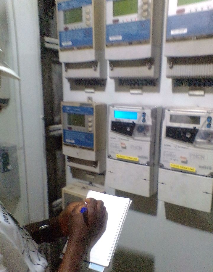
3.4.1.1. THE ENERGY READING FOR THE END OF THE MONTH
The term Energy in the TCN is referred to the act of collecting energy or power to be transmitted from the Generating stations to the Distribution stations. Through this process arises the generation of money to be paid by the Distribution companies in respect to the amount of power received by them from the transmission station in turn the capital given is directed to the generation and transmission company for each month.
Scope of the job
The total energy generated by the generating station for a month has been accumulated in an electrical device called The energy meter. Then the energy meter is set to display the energy accumulated over a period of a month.
The value given by the energy meter of the Generating station is then compared with that of the transmission station.
THE ENERGY METER
3.4.1.2. ANNUAL PREVENTIVE MAINTENANCE OF CIRCUIT BREAKERS
Annual preventive maintenance is a schedule maintenance of power equipments like the circuit breaker, transformer, current transformer. The annual preventive maintenance is done so as to prevent any unforeseen faults that could possibly occur in the equipments.
Scope of the job
First, the equipment(circuit breaker) is cleaned and dusted with a broom to remove all sorts in the breaker and clean the SF6 gas indicator casing if dirty.
The functionality and operational test is then carried out during this process, the circuit bis test run by opening and closing the breaker locally( manually) if it operates then it is tested on remote from the control room.
3.4.1.2. MAINTENANCE OF CIRCUIT BREAKERS
The maintenance or repairs of circuit breakers are corrective actions taking on a circuit breakers that developed faults over time.
The following jobs are based on the maintenance of circuit breakers;
The replacement of burnt closing coil in the circuit breaker.
The failure of the hydraulic oil pump motor to actuate.
The failure of a circuit breaker not to close.
3.4.1.2.1. REPLACEMENT OF BURNT CLOSING COIL IN THE CIRCUIT BREAKER
The closing coil or tripping coil energize the breaker by putting more pressure on the hydraulic oil pump motor to actuate the hydraulic oil for the closing operation of the circuit breaker.
Scope of the job
The circuit breaker C.B #3112 failed to close after investigation, it was discovered that the closing coil was burnt. Therefore, the closing coil was first measured to confirm it’s actually burnt in ohms(resistance), the result was above 30 ohms which means it is damaged, a good coil value must be less than 30 ohms.
A newly reminded coil of 24.6 ohms was used to replace the burnt coil, it was inserted into its coil case . Ensure the push button on the case is free.
Operate the circuit breaker locally and remotely to confirm its actuate the oil when closed and opened.
3.4.1.2.2. FAILURE OF THE HYDRAULIC OIL PUMP MOTOR TO ACTUATE DUE TO DEFECTIVE MOTOR RELAY CONTACTOR
The Hydraulic Oil Pump Motor: This is an electrical device that comes up or operates whenever the pressure in the circuit breaker is getting low, it operates so as to actuate or pressurize the circuit breaker hydraulic oil system to a pressure between 27MPa to 30MPa.
The Motor Contactor: The motor relay Contactor is an electrical equithat picks up the D.C. current signal from the source and sends it to the hydraulic oil pump motor in order to actuate the hydraulic oil system.
An Over-load Relay y Contactor: It is an electrical equipment that serves as protection for the motor contactors in case of a power surge or high current.
Scope of the Job
During the annual preventive maintenance of the circuit breaker #3223, when the functional test was carried out , it eas discoveredthat the hydraulic oil pump motor failed to come up, after investigation it was discovered that the motor contactor was defective.
The motor contactors and over-load relay contactor was replaced to a better one and operated which the circuit breaker then became ready for service.
3.4.1.2.3. THE FAILURE OF A CIRCUIT BREAKER TO CLOSE
All the faults that occurs in a circuit breaker causes it not to close, the fault encountered or discovered in the circuit breaker was that, the circuit breaker failed to close due to excess SF6 gas in the circuit breaker, this was caused by expansion of the gas due to increase in temperature of the atmosphere.
Scope of the Job
The SF6 gas was maintained (reduced) to its normal gauge of between 27MPa to 30MPa, in this case 28MPa.
3.4.1.3. THE DESIGN OF A PROTECTION WIRING SCHEME MODIFICATION
In the OTA 132/33kV transmission station, the OTA/OGBA 132kV line tripped on no relay indication. Therefore, a protection wiring scheme modification is done on the relay.
A protection wiring scheme modification can be referred to as the act of designing a new modified wiring for the protection of a relay. The protection wiring scheme modification is designed so as to meet the need of the fault a ground.
Scope of the Job
The fault in the relay panel is that the relay tripped without no indication, that is, the tripping or trip signal did not come from the Optimal distance relay or the Backup Siemens O/C + E/F relay.
Therefore, a protection wiring scheme diagram is designed to discriminate the trip signal between the Optimal distance relay and the backup Siemens O/C + E/F. That is whenever the relay trips on either each way it trips , the trip signal would be help down to know or indicate the type of tripping.
The connection is then carried out in the relay panel according to the protection wiring scheme diagram.
.
THE WIRING SCHEME MODIFICATION DIAGRAM
3.4.1.4. REARRANGEMENT OF THE WIRING SYSTEM OF A CIRCUIT BREAKER
In the OTA Transmission station, it was discovered that the newly installed circuit breaker wiring connections are not in comparison with manufacturer’s circuit diagram.
Scope of the Job
The circuit breaker manufacturer’s circuit diagram is used to know how the circuit breaker should be connected.
The number tags and their functions are compared in the circuit breaker and circuit diagram to be traced out if they are not the same, they are to be corrected.
After all the tracing and corrections, the circuit breaker is operating both locally and remotely.
The Circuit diagram used during the rewiring of the circuit breaker
3.4.1.5. INSTALLATION AND COMMISSIONG OF A TRANSFORMER
Before the installation and commissioning of a transformer, the following maintenance tests and services are carried out on the transformer and they are as follows;
Calibration and tests of the the 3.3kV indoor bus bars and associated components
Calibration and tests of incomer 3.3kV breaker, transformer primary and secondary breaker.
Calibration and tests of transformer primary and secondary current transformer (CTs)
Calibration and tests of the transformer relays.
Checks and tests of underground cables associated with transformer secondary side.
Checks, wiring and tests on transformer protective device systems.
Site confirmatory tests on the transformer after repairs.
Maintenance of transformer primary and secondary panels.
The checks and tests of the substation earthing system.
The irregular voltage of 3.3 kV occurs in the indoor circuit breaker of the incoming transformer panel because it was built by the Chinese, therefore, the indoor circuit breaker contains all its necessary protection.
Scope of the Job
The Calibration and Tests of the 3.3kV Indoor Bus-Bars, the Incomer 3.3kV Breaker, Transformer Primary and Secondary Breaker and Associated Components:
Under this maintenance, the insulation test of the 3.3kV indoor bus bars are done, it is done so as to know the rate of preventing the leakage current (I.e energy loss) using a high voltage Megger of a constant voltage of 5000V which measures in megaohms. The reason behind this test is to know the insulation value of each bus bar phase, a good insulation value ranges from 180000 to 200000(infinity) megaohms.
The higher the resistance value gotten from each phase, the better the chances of preventing leakage current.
The Calibration and Tests of the Transformer Primary and Secondary Current Transformer (CT):
The importance of the test on the primary current transformer is done so as to confirm the functionality of the current transformer. It is done with the aid of a Primary Current Injection Test Set called Megger, in this way, a current of 200A is injected into the primary, a current not less than 2.5A would be in the Secondary.
The Secondary Current Transformer is also tested by the aid of a Secondary Current Injection Test Set called Hypotonic. It is used to set the minimum current at which the indoor circuit breaker relay trips, which was set t to trip at a current of 3.3A, it helps improve the relay protection of the indoor circuit breaker.
The Calibration, Checks and Tests of the Transformer Relays abd the Underground Cables Associated with the Transformer Secondary Side:
The calibration and tests of the transformer relay is done by checking the resistance level of the transformer phase with the aid of a Megger. The checks done on the Underground cables is done to confirm the Underground cables are not damaged on the outside and a continuity test is also done on the cable by the aid of a digital meter.
Checks, Wiring and Tests on the Transformer Protective Device Systems:
Under this procedure, checks are done on the control cable if it is intact, the checks include the oil temperature alarm, the pressure relief trip, and so on.
The tests done includes the functionality test of the protection devices of the transformer which includes the Buchholz relay, Earth fault relay, Over-current relay, Differential relay and digital relay by actuating it to be in sequence o alarm by putting in a positive to make it trip for confirming if it is working properly. They include; The magnetization test, Core balance test, Ratio test, short circuit test and insulation resistance test.
Maintenance of Transformer Primary and Secondary Panels, Checks and Tests of the Substation Earthing System and the Site Confirmatory Tests on the Transformer after Repairs:
The maintenance of the transformer primary and secondary panel involves checking of the transformer primary and secondary panel in order to remove any form of moisture for preventing Earth fault in terms of voltage transfer in the transformer through induction to avoid earth fault(E/F) trip.
3.4.2. Experience Gained
Under my stay in the PC&M department during their work apart from the carrying out of a annual preventive maintenance of a circuit breaker, they work with the manufacturer wiring diagram of the equipment to be worked on. Therefore, I gained the following;
I learnt how to take energy readings from a meter.
In the maintenance(repair) of a circuit breaker, if the circuit breaker fails to close, I learnt that it is important to check and investigate the fault in the circuit breaker before beginning the job.
3.5. THE SYSTEM OPERATIONS DEPARTMENT
The System Operations also known as the Independent System Operators(ISO) department. At the end of my schedule with the Protection, Control and Metering department, I resumed at the system operations department(ISO) where I spent three weeks (9th to 28th of March , 2020). This department is led by the principal manager named ENGR. K. Muyiwa as the HOD. This department is responsible for the monitoring of the electrical transmission line, grid and the switch yard including the faults in the control room or with the relay panels.
The functions of an operator in the control room involves the following:
The monitoring of the proper operation of the station equipments in the control room and in the switch yard.
The quick response to system disturbance. In the sense of fluctuations of the loads on the grid which in turn leads to the fluctuation of voltage, current and frequency in the grid.
The load management of the electricity system grid: Load management can be referred to as the means or way of keeping the electricity system grid in equilibrium, whereby the power distribution across the national grid results to the power demanded. In other words, it is the balancing of the power on the grid with the load on the grid to be at equilibrium.
The collection of data from various substations under the Area Control Center i.e. the ACC. This data include the voltage transmitted by the station at every hour interval.
The recording of events that is being carried in and out of the station. I.e the station situation report and the filling of the daily logbook.
The carrying out of switching operations and to ensure safety of personnel and system equipments.
To make sure that the power transmitted from the Generating company to the grid at a minimum load loss.
3.5.1. WORK DONE UNDER THE SYSTEM OPERATIONS DEPARTMENT
Under the system operations department, the work done there are on a daily basis which includes;
Filling of the hourly load reading sheet at an interval of an hour(0000HRS, 0100HRS, 0200HRS, 0300HRS, …).
Taking of the periodic energy readings at an interval of 6 hours daily (0000HRS, 0600HRS, 1200HRS and 1800HRS).
Updating of the transmitted voltage data collected from various substations under the Olorunsogo Area Control Center, ACC into the Regional Control Center, RCC which is the Ikeja West Transmission Station for safe keeping of the data soft copy.
The Transmission Station situation report has to be filled everyday for the previous day i.e the station report for Tuesday is going to submitted on Wednesday.
All the work mentioned above are daily activities;
The issuing of operating form.
3.5.2. WORK EXPERIENCE GAINED
The experiences gathered during the attachment in this department are as follows:
Routine inspection and daily checks: this involves a walk around the switchyard by the operator, inspecting and checking the working conditions of the equipment, ensuring the pressure in the gas circuit breakers are normal, taking readings of the temperature of the windings of the transformers in the station, the checking of 110 and checking the electrolyte level in the batteries (for batteries that use electrolyte) so it does nothing get below the minimum, also inspecting the terminals for corrosion.
Taking hourly readings from the SCADA system form all the outgoing terminal feeders and the periodic energy readings at six hours interval.
Receiving and passing reports: reports including tripping and transformer and feeder load flow are received from substations within the area control; reports of the station activities are also passed to the Regional Control Centre (RCC).
Filling of the station situation report.
How to apply for, and issue station guarantee for several purposes. Also learnt how to isolate and de-energize a line, also to lift isolation and energize.
How to apply for an outage request.
3.5.3. EQUIPMENTS AND MATERIALS USED IN THE SYSTEM OPERATIONS
In the department of the system operations, the following equipments or tools and materials are listed below:
Frequency monitor
Relay panels
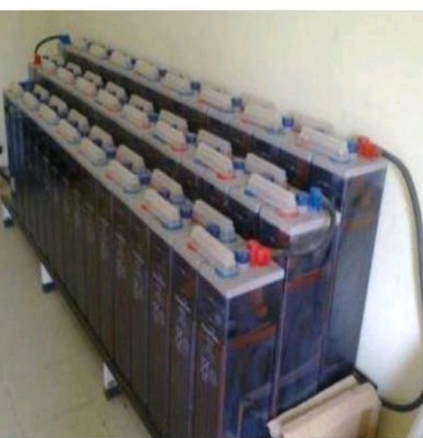
The 110V DC battery bank
A desktop system
The Log book
Operating forms
Energy meter
Hourly reading sheets, and
The SCADA
FREQUENCY MONITOR: The frequency monitor is used to know the frequency of the electricity national grid. The frequency is said to be uniform across the national grid all over the Transmission Station in the country. The frequency on the national grid is highly load dependent, therefore it fluctuates based on the load generated and demanded, that is, if the power generated is lower than the power demanded, then the frequency is going to be low and if the power generated is higher than the power demanded, then the frequency would be high.
The normal range of values for frequency is between 50.1 Hz to 50.5 Hz. Therefore, anything lower than 50.1 Hz means the energy generated is low and if it continues to drop, then the NCC would be informed and they would direct some station to drop load from their feeders. This process is known as load shedding (load shedding is the deliberate removal of loads from a feeder so as to either boost the frequency rationing or as well as the transformer capacity). If the frequency tends to rise above 50.6Hz means the energy generated is higher than the energy demanded, then the NCC is also informed which would call for load picking. In other words, all these processes are known as load management.
Relay panels: Relay panels are constructed housing for the relays which helps to facilitate the easier and faster detection of faults as they are sensitive to any fluctuation on the grid so as to give the alarm once a fault or fluctuation is detected.
The 110V direct current (DC) battery bank: The 110V DC battery bank is termed generally as the life of any transmission station at the operations department. This because it is responsible for the powering kf all the relays and control panels equipments used for monitoring the grid. It aids in relay co-ordination, relay co-ordination is the activity of a relay to detect faults and cut off that fault only with the help of the battery bank, because it is the battery bank that provides the electrical power to send signals to the circuit breaker in order to trip while cutting the fault off.
Desktop computer: The computer is one of the tools or equipments used by the operators. It is used to upload the load data collected from other substations, to be filled into the RCC platform. It is used for the safe keeping of the station situation report soft copy, the processing and issuing of outage request form etc.
Log book: The log book can be referred to as a material used for the recording of the daily activities in the office, it is more of a material used for documenting the summary of all occurrence including the time they occurred for safe keeping of the hard copy after all important details and data had been logged into the system.
The operating forms: The operating forms are important forms conveying details on the type of equipment to be worked on, the name of the leader of the maintenance crew to work on the equipment, the name of the operator on duty as at the time the job is to commence and the time the job starts and is expected to end. These operating forms are to be filled by the operator on duty and the permit holder that is the leader of the maintenance crew, when a job is to proceed at the station. There are seven(7) types of operating forms, namely; Operating form(O.F) 1, O.F 2, O.F 3, O.F. 4, O.F 11, O.F 19 and Hold-off tags.
Operating Form1: The operating form 1 stands for the application for protection which is filled by the Transmission Service Provider, TSP, before commencing any job.
Operating Form 2: This is known as the Work permit, it is filled by the operator on duty and the permit holder. This type of form is given when the job involved does not require any testing for functionality.
Operating Form 3: It serves as a Station Guarantee. A Station Guarantee form is a type of form given by the Transmission Company of Nigeria to either the Generating company or the Distribution company by the operator on duty so as to assure the safety of an equipment from the Transmission end before working on the equipment at there end.
Operating Form 4: This is the Work and Test permit, it is similar to the work permit, but the only difference is that this permit gives room for the testing of the electrical equipment.
Operating Form 11: It is known as the self protection form. The difference
between the O.F 11 an other Operating Forms is that the equipment involved with O.F 11 are low voltage equipments which does not require any necessary isolation by the operator. Examples of this kind of jobs are that of maintenance of battery banks and illumination of the switch yard.
Operating Form 19: This is the Trouble Report. The Trouble Report is being filed by the operators and submitted via emails to the TSP whenever they notice any fault on any equipments that needs attention or repairs.
Hold-off Tags: This is a kind of special permit used by the TSP crew when working on the Transmission line that ensures guarantee on jobs that does not require an outage on that line, but if the line should trip, then the operator must communicate with the maintenance crew to confirm if it was their action that lead to the tripping.
THE OPERATING FORMS
Energy Meter: The energy meter is a digital electronic equipment that store and measure the energy that is being transmitted by the transformer it is being connected to for over a long period of time. It is used to record the periodic energy readings at the interval of 6 hours daily.
The Hourly Reading Sheet: This is also a material used by the operator daily. It is used to take Hourly load read reading which contains the power(MW), Current(Amps), Voltage(kV), the Loads (MW) on the grid and (MVAR) at hourly basis, with the aid of the SCADA system.
The SCADA: SCADA is an acronym for Supervisory, Control And Data Acquisition. It’s function is to Supervise, Control and Acquiring Data.
A SCADA system includes the following:
One or more computers connected to each other, perform the Supervisory functions and implement human-machine interface (HMI).
A communication network with a variety of transmission media and communication protocols, able to ensure the correct exchange of data between peripheral devices and Supervisory computers.
A SCADA software is an integrated development environment, which provides all the tools necessary to create SCADA applications, designed to run on Supervisory computers and perform the functions that are typical of a SCADA system; Supervisory, Control and Data Acquisition.
The Supervisory functions of a SCADA allow s the operator to have an immediate view of the process status and to control how the process evolves over time by analyzing the sequence operating states. The main task of the supervision is to realize the human-machine interface HMI to be effective.
The Control function of a SCADA system consists in the ability of the control system to interact with the controlled process, in order to modify its evolution according to pre-establish rules or decisions taken by the operator.
Data Acquisition is the main functions among those performed by SCADA system. The data acquisition not only means transfer of information from peripherals devices to Supervisory computers, but also transfer of information in the opposite direction, in order to allow the supervisory system to get all the information on the process status that are necessary to allow the observation. It’s task is to ensure the error-free transfer of information between process and supervision.
CHAPTER FOUR
THE EQUIPMENTS USED IN THE PAPALANTO WORKS CENTRE
4.1. INTRODUCTION
This chapter entails the equipment used, the functions of the equipment used and the descriptions of their usage during the cause of this attachment at Transmission Company of Nigeria, Ganmo.
The equipment used is as follow;
Auto-Transformer
Wave traps
Instrument transformers
The circuit breakers
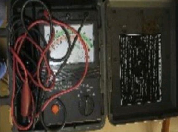
The insulation resistance tester (Megga)
The leakage current tester (Clamp on)
Earthing transformer
Bus isolators and Isolators
Relays and control panels
The Secondary current injection test set.
4.2. THE FUNCTIONS AND USAGE OF THE ELECTRICAL EQUIPMENTS
THE AUTO-TRANSFORMER
A transformer is a static machine used for transforming power from one circuit to another without changing frequency. Auto-transformer is a single-winding transformer with taps. With primary voltage applied to the primary terminals, the required secondary voltage from zero volts to the rated primary volts can be availed from the secondary by varying the taps.
FUNCTIONS OF AN AUTO-TRANSFORMER
Auto-transformer is a power transformer that has incorporated into it a higher level of control techniques and is mostly used in transmission station. An autotransformer is used mainly for the adjustment of line voltages to either change its value or keep it constant.
It functions as step down transformer and it keeps the output voltage i.e. secondary voltage constant by the use of tap-changer feature of the auto-transformer.
It is a power transformer used in electrical power stations
USAGES OF AUTO-TRANSFORMER
The usage of autotransformer in Transmission Company of Nigeria is to step up or step down the HVAC to a certain values and maintain a constant output voltage i.e. secondary voltage by tap-changing the winding inside the transformer using the Tap-Changer built with the transformer for the ability to change the position of the secondary winding to maintain a constant output secondary voltages.
Auto-transformers are frequently used in power applications to interconnect systems operating at different voltage classes, for example 330kV to 132kV for transmission.
On long rural power distribution lines, special autotransformers with automatic tap-changing equipment are inserted as voltage regulators, so that customers at the far end of the line receive the same average voltage as those closer to the source. The variable ratio of the autotransformer compensates for the voltage drop along the line.
THE 105MVA TRANSFORMER OF RATING 10/330kV AT OLORUNSOGO PHASE 1
THE WAVE TRAPS
Wave trap is an electrical equipment used on the outgoing or incoming line into a Station, as its name indicates that it is used to trap frequency waves.
FUNCTIONS OF WAVE TRAPS
The carrier energy on the transmission line must be directed toward the remote line terminal and not toward the station bus and it must be isolated from bus impedance variations. This task is performed by the line trap.
A parallel resonant circuit has high impedance at its tuned frequency, and it then causes most of the carrier energy to flow toward the remote line terminal. The coil of the line trap provides a low impedance path for the flow of the power frequency energy. Since, the power flow is rather large at times, the coil used in a line trap must be large in terms of the size. Hence, a line trap unit/Wave trap is inserted between bus bar and connection of coupling capacitor to the line. It is a parallel tuned circuit comprising of inductance (L) and capacitance (C). It has low impedance (less than 0.1Ω) for power frequency (50 Hz) and high impedance to carrier frequency. This unit prevents the high frequency carrier signal from entering the neighbouring line.
WAVE TRAPS
INSTRUMENT TRANSFORMERS
Instrument transformers are primary used to provide isolation between the main primary circuit and the secondary control and measuring devices. This isolation is achieved by magnetically coupling the two circuits. In addition to isolation, levels in magnitude are reduced to safer levels.
Instrument transformer are divided into two categories;
(i) Voltage Transformers (VT), VTs have a successor called Capacitor Voltage Transformers (CVT), and (ii) Current Transformer (CT).
The primary winding of VT is connected in parallel with monitoring circuit, while the primary winding of the CT is connected in series with monitoring circuit.
FUNCTIONS OF AN INSTRUMENT TRANSFORMER
- To transform currents or voltages from a usually high value to easy to handle for relays and instruments.
- To insulate the metering circuit from the primary high voltage system.
- To provide possibilities of standardizing the instruments and relays to a few rated currents and voltages
USAGES OF VOLTAGE TRANSFORMER (VT) AND CAPACITOR VOLTAGE TRANSFORMER (CVT)
1. The secondary windings proportionally transform the primary levels to typical values of 110V phase to phase.
2. The secondary voltage can be used in switchgear compartments, where it may be used to drive motors that open and close circuit breakers.
3. The secondary voltage can be used in voltage regulators, where it can power a tap-changing drive motor of the Power Autotransformer above.
4. It used for protections of both the equipment in the station and personnel.
5. The secondary voltage is used for metering and operating protection relays such as Over Voltage protection, Under Voltage protection, Over frequency protection, Under frequency protection, Distance Protection, Transformer Differential protection et cetera.
6. The CVT is also useful in communication systems. CTVs in combination with wave traps are used for filtering high-frequency communication signals from power frequency. This forms a carrier communication network throughout the transmission network.
CT at Olorunsogo 330kV. VT at Papalanto 132kV T.S. The Line CT at OTA T.S.
USAGES OF CURRENT TRANSFORMER (CT)
A current transformer can be used in:
To transforms the current on the line to that which is suitable for the meters and relays to function.
Metering of power to track energy use.
Monitoring of current flow through a circuit. This can be used to monitor the amount of current drawing by are line and the maximum allow current can be set on relay to trip on over current protection.
Relay of power through an energy grid.
Control of the state of circuit (open or closed) in a ground fault circuit interrupter.
Protection of instruments and appliances connected to AC power supplies as well the personnel working at TCN.
CIRCUIT BREAKERS
Electrical circuit breaker is a switching device which can be operated manually as well as automatically for controlling and protection of electrical power system respectively. As the modern power system deals with huge currents, the special attention should be given during designing of circuit breaker to safe interruption of arc produced during the operation of circuit breaker.
There are four type of circuit breaker namely; Air Circuit Breaker (ACB), Oil Circuit Breaker(OCB), SF6 Circuit Breaker and Vacuum Circuit Breaker. They types that is employed at TCN Papalanto, and its substations are Oil Circuit Breaker (OCB) and Spring Charging Circuit Breaker by operating mechanism.
FUNCTIONS OF CIRCUIT BREAKER
The main functions of circuit breakers are;
Sense the current flowing in the circuit
Measure the current flowing in the circuit
Compare the measured current level to its pre-set trip point
Act within a predetermined time period by opening the circuit as quickly as possible to limit the amount of energy that is allowed to flow after the trip point has been reached.
USAGES OF CIRCUIT BREAKERS
This equipment is used to make or break a circuit or segment of it, for the purpose of preventing Electrical Energy from getting to certain segments of the transmission and/or station. The circuit breaker can operate under normal (when it is operated deliberately) and abnormal conditions (when its contacts open on discovery of a fault within its jurisdiction). Its contacts are embedded in a medium which function as insulation and arc quenching during operation. Its contacts are not visible to the human eyes; however it could have an indicator telling whether the circuit breaker is opened or closed. The medium could be air, oil, gas (Sulphur hexafluoride SF6 gas is widely used), vacuum (absence of oxygen eliminates combustion). The advantages of Gas Circuit Breakers (GCB) over the Oil Circuit Breaker (OCB) are as follows;
Oil is combustible and could cause fire outbreak if arcing current is very high.
Carbonization of the oil takes place when the contacts are made or broken due to arcing.
When the contacts are made or broken, the oil gradually reduces in insulation strength and may result in breakdown, or must be changed regularly.
The gases used in the GCB are usually more efficient than using the OCB.
The GCB provides neater working environment around the breaker than the OCB.
THE HYDRAULIC OIL AND SPRING CHARGING CIRCUIT BREAKERS BY OPERATION
INSULATION RESISTANCE TESTER (MEGGA)
Insulation resistance quality of an electrical system degrades with time, environment condition i.e. temperature, humidity, moisture & dust particles. It also get impacted negatively due to the presence of electrical & mechanical stress, so its become very necessary to check the IR (Insulation resistance) of equipment at a constant regular interval to avoid any measure fatal or electrical shock.
USAGE OF MEGGA
A Megohmmeter usually is equipped with three terminals. The “LINE” (or “L”) terminal is the so-called “hot” terminal and is connected to the conductor whose insulation resistance you are measuring. The tests are performed with the circuit de-energized.
The “EARTH” (or “E”) terminal is connected to the other side of the insulation, the ground conductor.
The “GUARD” (or “G”) terminal provides a return circuit that bypasses the meter. For example, if you are measuring a circuit having a current that you do not want to include, you connect that part of the circuit to the “GUARD” terminal.
THE INSULATION RESISTANCE TESTER (MEGGA)
LEAKAGE CURRENT TESTER (CLAMP ON)
In any electrical installation, some current will flow through the protective ground conductor to ground. This is usually called leakage current. Leakage current most commonly flows in the insulation surrounding conductors and in the filters protecting electronic equipment around the he or office. So what’s the problem? On circuits protected by GFCIs (Ground Fault Current Interrupters) e.g. Circuit Breaker, leakage current can cause unnecessary and intermittent tripping. In extreme cases, it can cause a rise in voltage on accessible conductive parts.
USAGE OF LEAKAGE CURRENT TESTER
The Clamp-on is use in TCN to detect leakage current in secondary terminal of a CT while performing maintenance and detecting the start of the windings and insulation of the CT. The Clamp-on is clamp on the shorted secondary terminals of the CT while a known current has been injected to the primary side of the CT to test.
EARTHING TRANSFORMER AND EARTH REACTORS
The general purpose of earthing system is to protect life and property in the event of 50/60 Hz faults (short-circuit) and transient phenomena (lightning, switching operations).
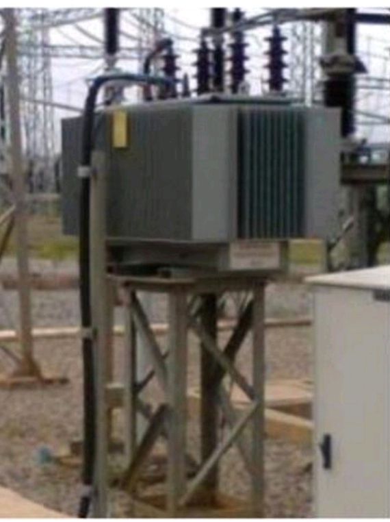
FUNCTIONS AND USAGES OF EARTHING TRANSFORMER
This is used as earthing for the auto transformer and likewise as auxiliary supply for station. The earthing transformer serves as the neutral for the secondary of the transformer as step down of the 33KV at the tertiary to 415V, which is used for station auxiliary supply.
For cases where there is no neutral point available for Neutral Earthing (e.g. for a delta windings), an earthing transformer may be used to provide a return path for single phase faults currents.
In such cases the impedance of the earthing transformer may be sufficient to act as effective Earth impedance. Additional impedance can be added in series if required. A special ‘zig-zag’ transformer is sometimes used for earthing delta windings to provide a low zero-sequence impedance and high positive and negative sequence impedance to fault currents.
In a three phase delta connected AC system, an artificial neutral grounding system may be used. Although no phase conductor is directly connected to ground, a specially constructed transformer (a “zigzag” transformer) blocks the power frequency current from flowing to Earth, but allows any leakage or transient current to flow to ground.
BUS ISOLATORS AND LINE ISOLATOR
Isolators are a mechanical switching device used to disconnect some portion of the circuit. It is basically operated when the load is already cut off. Like circuit breaker, Isolator is also used in making and breaking the circuit, but there is major difference that is, Circuit Breaker is on Load device and isolator is operated when the load is off or disconnected
132kV ISOLATOR. THE 330kV BUS ISOLATOR. THE 330kV LINE ISOLATORFUNCTIONS AND USAGE OF AN ISOLATOR
i. Isolators are used to open a circuit under no load.
ii. It is a manually operated mechanical switch which separates a part of the electrical power.
iii. Isolators are generally used on both ends of the breaker in order that repair or replacement of circuit breaker can be done without and danger.
iv. Isolators connected on any line or circuit can be electrically or manually operated for either emergency or maintenance.
RELAYS
Relay is an automatic protective device designed to trip a circuit breaker when a fault is detected. The protective relays were electromagnetic devices, relying on coils operating on moving parts to provide detection of abnormal operating conditions such as over-current, over-voltage, reverse power flow, over-frequency, and under-frequency.
Some Relays used in Sub-Station
i. Over Current Relay
ii. Over Voltage Relay
iii. Differential Relay
iv. Restricted Earth Fault Relay
v. Buchholz Relay.
.
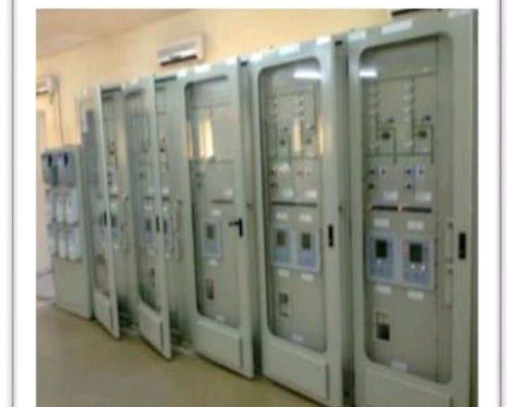
FUNCTIONS OF A RELAY
It protects the transmission station against the following:
I. Itprotects against over current. The relays trip when a current rises above a set point which can be caused by either the load or the supply such as a sudden increase in load due to faulty.
ii. It function as a protective device when there is an over voltage. That is, relays trip when a voltage rises above a set point.
iii. It provides protection against earth fault. That is, relays detect any undesired current path from a point of differing potential to ground.
SECONDARY INJECTOR
It is a method of connecting a secondary injection test set to a trip unit (trip device, over current module, protection device, OCR, ETU etc.) on a circuit breaker, VT and CT, and injecting a simulated current to prove it works at different levels.
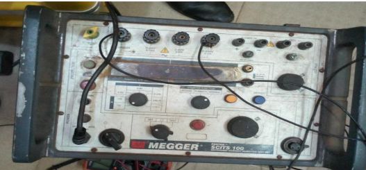
Secondary current Injection
FUNCTIONS OF SECONDARY INJECTION
I. Primary and secondary current injection tests are normally conducted to check the operation of breaker and their protective relays/devices.
ii. The protective devices installed vary from circuit to circuit depending on the protection needs but typical relays/devices include overload, over current, reverse power, earth fault, and differential protection.
CHAPTER FIVE
CONCLUSION, PROBLEM ENCOUNTERED AND RECOMMENDATION
5.1. CONCLUSION
Transmission Company of Nigeria, Papalanto has given me the opportunity to have an experience in general, considering my level of involvement in some technical work and being able to witness the various application of the theoretical aspect of education which I am conversant with.
5.2. PROBLEM ENCOUNTERED DURING THE SIWES TRAINING
The problems of securing a place of attachment as some of the organizations dont want to accept SIWES students.
Finance department of the company did not make proper provision to pay SIWES student nor do draft any allowance, packages so as to relief the expenses for themonths programme.
Difficulty to understand some technical explanations as limited time is met for work done.
The biggest problem faced so far is getting to the office caused by traffic, money available at hand.
5.3. RECOMMENDATION FOR IMPROVEMENT OF THE SCHEME
Based on the experience and knowledge acquired at the course of the SIWES training, I hereby give the following recommendation base on my observations;
Institution should ensure that students are attached at relevant establishment for effective training, experience and exposure.
I recommend that substantial percent of the National budget should go into the development, improvement and sustenance of the power sector. Doing this would help improve Electricity production and in turn improve development and industrialization and subsequently, the income the country generates.
Also, Power Holding Company of Nigeria should put safety into great consideration; providing adequate safety wears for staff and ensuring their usage; putting that in mind.
I strongly suggest that SIWES student should be paid at monthly basis so as to ease the burden of transportation being the main problem faced.