
Key learnings
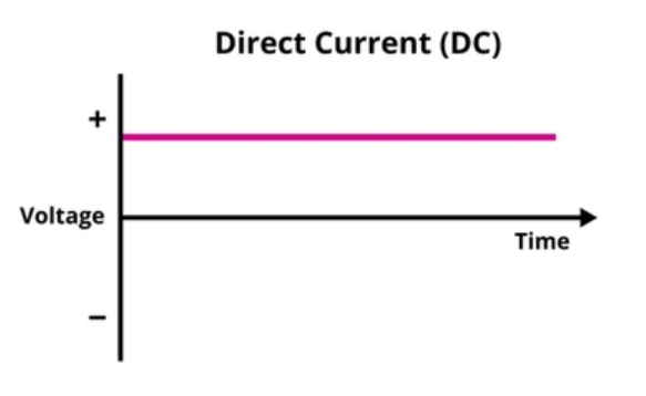
- DC voltage has a fixed polarity: one point remains positive relative to another, even if the voltage’s magnitude changes.
- The common DC symbol is ⎓—a solid line above a dashed line. Multimeters often show it beside
V. - Wire colors can help identify conductors, but they vary by country, standard, and installation. Always verify a wire before working on it.
- AC voltage regularly reverses polarity; DC voltage does not.
- Diodes and resistor dividers can reduce voltage in some situations, but they are not suitable substitutes for a voltage regulator in every circuit.
- A boost converter can raise a DC voltage. A conventional transformer requires changing current and does not step up steady DC.
What is DC voltage?
DC stands for direct current. DC voltage is a potential difference with a polarity that stays the same. The voltage’s size may be constant, as with an ideal battery, or it may rise and fall while retaining the same polarity, as in a rectified supply with ripple.
Voltage is the difference in electric potential between two points. It describes how much energy is transferred per unit of electric charge:
V = \frac{W}{Q}
Here, V is voltage, W is energy transferred, and Q is electric charge. Voltage is measured in volts (V).
A battery is a familiar DC source. Its positive and negative terminals define the polarity of the voltage it supplies. Other DC sources include solar panels, USB power supplies, and the DC output of a rectifier or power converter.
Does DC voltage have zero frequency?
A perfectly constant DC voltage has no repeating cycles, so it is often described as having zero frequency. Real DC supplies can contain ripple or other variations. They are still generally called DC when their polarity does not periodically reverse.
So, DC does not always mean perfectly flat or unchanging voltage. The key distinction from AC is whether the polarity reverses.
DC voltage symbol
The common symbol for DC is ⎓, a solid horizontal line above a dashed line. On a multimeter, it is usually shown next to V, as in V⎓. AC voltage is commonly marked V~. Fluke’s guide to multimeter symbols
In circuit diagrams, a battery is shown using pairs of parallel lines of unequal length. One long-and-short pair represents a cell; several pairs represent multiple cells. A DC supply may also be shown with a circle or other source symbol marked with + and −.
Ideal and practical voltage sources
An ideal voltage source maintains the same terminal voltage regardless of how much current the connected circuit draws. It has zero internal resistance.
A practical source, such as a battery, has some internal resistance. When it supplies current, the voltage measured at its terminals may fall. A simple model is:
V_{\text{terminal}} = V_{\text{source}} - I r_{\text{internal}}
Here, I is the current drawn and r_internal is the source’s internal resistance. This model helps explain why an old battery may show a reasonable voltage with no load but drop noticeably when connected to a device.
DC voltage wire color codes
Wire colors are used to help identify a conductor’s purpose, but the color scheme depends on the applicable standard and installation. It can also vary with system design, whether conductors are grounded, and the age of the wiring.
Never identify a wire by color alone. Check the wiring diagram, labels, local electrical code, and the actual circuit with suitable test equipment. If you are unsure, have a qualified electrician identify it.
IEC conductor identification
IEC 60445 covers identification and marking of equipment terminals and conductors. Its current published version is IEC 60445:2021 with amendment 1 from 2026. The standard provides identification rules; local jurisdictions may adopt or modify standards, so confirm which rules apply to a particular installation. IEC 60445 publication information
Under IEC 60445:2021, where colors are used to identify DC line conductors, the listed colors include red for positive and white for negative; blue identifies a neutral or midpoint conductor where applicable. Protective conductors use green-and-yellow identification. These assignments differ from some color tables found online, so confirm the current locally adopted requirements before relying on them.
| Conductor function | IEC identification shown in IEC 60445:2021 |
|---|---|
| Positive DC line | Red |
| Negative DC line | White |
| Midpoint or neutral, where applicable | Blue |
| Protective conductor | Green and yellow |
Color tables may differ between standards and types of system. A conductor’s color is not proof that it has a particular voltage or polarity.
United States wiring
In the United States, conductor identification depends on the type of circuit and the applicable National Electrical Code requirements. There is no single color table that should be assumed to cover every DC installation, especially equipment, vehicles, batteries, and control wiring. Follow the circuit documentation and the rules adopted by the relevant authority.
DC voltage compared with AC voltage
Alternating current (AC) periodically changes direction. The voltage polarity across the source reverses as the waveform changes. Household AC systems commonly operate at 50 Hz or 60 Hz, depending on the country.
Direct current (DC) maintains the same polarity. Its magnitude may remain constant or vary with time, but it does not regularly reverse polarity.
| Feature | DC voltage | AC voltage |
|---|---|---|
| Polarity | Remains the same | Reverses periodically |
| Magnitude | May be steady or vary | Usually varies periodically |
| Frequency | No repeating cycles for ideal steady DC | Has a frequency, such as 50 Hz or 60 Hz |
| Common sources | Batteries, solar panels, DC supplies | Utility mains, alternators |
How to reduce DC voltage
The right method depends on the load. A small voltage drop for a low-current signal is a different problem from powering a device that needs a stable voltage.
Reducing voltage with a diode
A forward-biased diode has a voltage drop across it. The drop depends on the diode type, current, and temperature; it is not a fixed value for every circuit.
For example, a silicon diode may have a forward voltage drop around 0.6–0.7 V under certain operating conditions, but the actual value varies. Schottky and other diodes also have current-dependent voltage drops.
Putting diodes in series can create a larger voltage drop, but the result changes with current and temperature. This method can waste power and may not provide the stable voltage a circuit requires. Check the diode’s datasheet and calculate the expected current before using it.
Reducing voltage with a resistor divider
Two resistors in series can divide an input voltage. If the output is taken across the lower resistor R2, the ideal unloaded output is:
V_{\text{out}} = V_{\text{in}}\frac{R_2}{R_1+R_2}
If R1 and R2 have equal resistance, the unloaded output is half the input voltage.
For example, with a 5 V input and equal resistors, the divider output is:
V_{\text{out}} = 5\ \text{V}\times\frac{1}{2} = 2.5\ \text{V}
A resistor divider’s output changes if the connected load draws significant current. It is generally useful for signals or other light loads, not for powering a load that requires a steady voltage. For that, use a suitable regulator or DC-DC converter.
Worked voltage-divider example
Suppose a 5 V source must provide an ideal unloaded output of 3 V, and R1 is chosen as 10 Ω. Find R2.
Start with the divider relationship:
V_{\text{out}} = V_{\text{in}}\frac{R_2}{R_1+R_2}
Substitute the values:
3 = 5\frac{R_2}{10+R_2}
Rearrange:
3(10+R_2) = 5R_2
30 + 3R_2 = 5R_2
R_2 = 15\ \Omega
This gives an ideal unloaded output of 3 V. In a real circuit, the load affects the divider output, so the resistor values must be chosen with the load current in mind.
How to step up DC voltage
A boost converter is a DC-DC switching converter that can produce a higher DC voltage from a lower DC input. It uses switching components and energy-storage components such as an inductor and capacitors.
A boost converter is not lossless. In a practical converter, output power is lower than input power because some energy is lost as heat and through switching and component losses. For a given power level, raising the voltage generally means the available output current is lower.
A conventional transformer works by electromagnetic induction, which depends on changing magnetic flux. Steady DC does not create a continuously changing magnetic field, so a transformer alone cannot step up steady DC. Switching converters solve this by switching the DC on and off to create changing currents inside the converter.
Measuring DC voltage with a multimeter
A digital multimeter can measure DC voltage when set to the correct function and range.
- Insert the black lead into the
COMterminal. - Insert the red lead into the voltage terminal, often marked
VorVΩ. - Select DC voltage, usually marked
V⎓. - Connect the probes in parallel across the two points being measured: red to the point expected to be more positive, black to the other point.
- Read the display. A negative reading usually means the probes are reversed relative to the source polarity.
Use a meter and probes rated for the voltage and type of circuit. Follow the meter’s instructions and electrical safety procedures. Fluke multimeter safety and measurement guidance
Common mistakes to avoid
- Thinking DC voltage must be perfectly constant. DC can contain ripple while keeping the same polarity.
- Confusing voltage with current. Voltage is potential difference; current is the flow of electric charge.
- Treating wire colors as universal. Color conventions vary by standard, region, and installation.
- Assuming a diode has an exact fixed voltage drop. Its drop depends on the component and operating conditions.
- Using a resistor divider to power a load without checking loading. The output voltage may fall when the load draws current.
- Connecting a conventional transformer directly to steady DC. Transformers rely on changing magnetic flux.
- Using a multimeter’s AC setting for a DC measurement. Select the DC voltage function marked
V⎓.
Conclusion
DC voltage maintains a fixed polarity, though its magnitude may vary. It is produced by sources such as batteries and solar panels, and it appears in circuits ranging from small electronics to power systems.
The DC symbol ⎓ helps distinguish DC from AC on meters and equipment. Wire colors can aid identification, but they are not universal: follow the locally applicable standard, check the circuit documentation, and verify conductors before working on them.
Diodes and resistor dividers can reduce voltage in limited situations, while voltage regulators and DC-DC converters are used when a more controlled supply is needed. A boost converter can raise DC voltage; a conventional transformer cannot do so from steady DC alone.