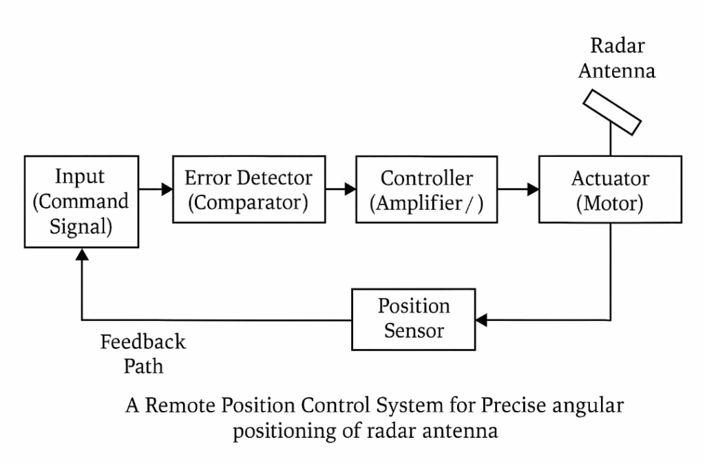
The question asks you to analyze the function and interaction of each element in a remote position control system for precise angular positioning of a radar antenna, using a schematic diagram.

To answer this:
Schematic Elements (Block Diagram Style):
- Input (Command Signal) – Desired antenna angle.
- Error Detector (Comparator) – Compares desired angle with feedback from the actual position.
- Controller (Amplifier/Servo Amplifier) – Amplifies the error signal.
- Actuator (Motor) – Converts electrical signal to mechanical motion.
- Radar Antenna – The load; receives motion and rotates accordingly.
- Position Sensor (Potentiometer/Encoder) – Measures actual antenna angle.
- Feedback Path – Sends actual position back to error detector.
Dynamic Interactions:
- Input vs Feedback: The system continuously compares desired and actual positions.
- Error Signal Flow: The error drives the motor until the antenna reaches the desired position.
- Feedback Loop: Negative feedback ensures precision by minimizing the error.
- Control System Dynamics: Involves time response, damping, and stability to avoid overshooting or oscillations.
