A PROJECT REPORT SUBMITTED OF ELECTRICAL ENGINEERING IN PARTIAL FULFILLMENT FOR THE AWARD OF NATIONAL DIPLOMA FACULTY OF ENGINEERING THE POLYTECHNIC IBADAN
MARCH, 2021.
AUTHENTICATION
I hereby certify that this project work “CONSTRUCTION OF A REMOTE CONTROL MOTOR CAR” was carried out by:
of the Department of Electrical Engineering, The Polytechnic, Ibadan.
____________ MR. S.O. OLAYIWOLA Supervisor
____________ ENGR. M.O. SADIQ Head of Department
TABLE OFCONTENTS
TITLE PAGE. i AUTHENTICATION ii TABLE OF CONTENT. iii CHAPTER ONE 1.1 INTRODUCTION 1 1.2 BACKGROUND OF THE PROJECT 1 1.3 PROBLEM STATEMENT 1 1.4 AIM OF THE PROJECT 2 1.5 OBJECTIVE OF THE PROJECT 2 1.6 SIGNIFICANCE OF THE PROJECT 2 1.7 BENEFIT OF THE STUDY 2 1.8 LIMITATION OF THE PROJECT 2 1.9 DEFINITION OF TERM 3 CHAPTER TWO 2.0 LITERATURE REVIEW 4 2.1 LITERATURE REVIEW OF REMOTE TECHNOLOGY 4 2.2 HISTORICAL BACKGROUND OF REMOTE CONTROL 5 2.3 REVIEW OF DIFFERENT TYPES OF REMOTE CONTROL CAR 9 CHAPTER THREE 3.0 METHODOLOGY 12 3.1 INTRODUCTION 12 3.2 BLOCK DIAGRAM OF THE SYSTEM 12 3.3 BLOCK DESCRIPTION 13 3.4 ELECTRONIC COMPONENTS USED 14 3.5 CIRCUIT DESIGN OF REMOTE CONTROL CAR 14 REFERENCE 18
ABSTRACT
This work is on a remote control motor car. Remote controlled car is battery/ powered model cars or trucks that can be controlled from a distance using a specialized transmitter or remote. This Radio controlled system is adopted in many vehicles like cars, boats, planes, and even helicopters and scale railway locomotives. In this work we will use a couple of ICs and a motor fixed to a chassis to make a remote control car. This work involve a brief idea is to transmit control signals through radio frequency and receive it through a receiver module in the car. We will have two switches in our remote control to power each motor of the car.
The objective of this project is to design a low cost remote control toy or robot. In this work we shall assemble the motors, circuit, and wheels on the chassis.
TABLE OF CONTENTS TITLE PAGE APPROVAL PAGE DEDICATION ACKNOWELDGEMENT ABSTRACT TABLE OF CONTENT CHAPTER ONE INTRODUCTION BACKGROUND OF THE PROJECT PROBLEM STATEMENT AIM OF THE PROJECT OBJECTIVE OF THE PROJECT SIGNIFICANCE OF THE PROJECT BENEFIT OF THE STUDY LIMITATION OF THE PROJECT PROJECT ORGANISATION
CHAPTER TWO LITERATURE REVIEW 2.0 LITERATURE REVIEW 2.1 LITERATURE REVIEW OF REMOTE TECHNOLOGY 2.2 HISTORICAL BACKGROUND OF REMOTE CONTROL 2.4 REVIEW OF DIFFERENT TYPES OF REMOTE CONTROL CAR
CHAPTER THREE 3.0 METHODOLOGY 3.1 INTRODUCTION 3.2 BLOCK DIAGRAM OF THE SYSTEM 3.3 BLOCK DESCRIPTION 3.4 ELECTRONIC COMPONENTS USED 3.5 CIRCUIT DESIGN OF REMOTE CONTROL CAR
CHAPTER FOUR RESULT ANALYSIS 4.1 CONSTRUCTION PROCEDURE 4.2 ASSEMBLING OF SECTIONS 4.3 MOUNTING PROCEDURE 4.4 TESTING 4.5 RESULT 4.6 ECONOMIC OF THE PROJECT 4.7 RELIABILITY 4.8 MAINTAINABILITY 4.9 PROJECT EVALUATION 4.10 BILL OF ENGINEERING MEASUREMENTS AND EVALUATION
CHAPTER FIVE CONCLUSIONS RECOMMENDATION 5.3 REFERENCES
CHAPTER ONE
1.0 INTRODUCTION 1.1 BACKGROUND OF THE STUDY Remote control car referred to as RC Car, RC is short for Radio control or Remote control. In Europe, Japan and Southeast Asian countries, the remote control model car race is a kind of sports competitions and a noble sport, even a high-tech hobby. This is a competition from age limit because enthusiasts who participate in this sport is aged from 8 to 80 years. This also suggests that the remote control cars is the same as remote control aircraft, whether adult or children can play. However, it has a certain degree of risk, because the remote control car is not a simple toy, its principle is the same as the real car. So, I still recommend that children would better to accompany by their parents. Electric remote control car is primarily provided power by an electric motor. Due to powered by a battery, it has higher overall operating efficiency and excellent acceleration performance of vehicles. Because of Clean Energy, the vehicle maintenance is very convenient, just pay attention to the maintenance of transmission parts. But because the electric motor remote control car need high requirements of motor performance and battery performance, so the motor and battery consumption is very high in the beginning, coupled with the electronic speed control, remote equipment costs. 1.2 PROBLEM STATEMENT Kids using manual car as fun or for recreation involved physical strength and sometimes can be hazardous in that they can be injured whenever the car crash with an object or obstacle. However, this device can overcome this problem. This device does not involve physical strength in that the motor is been controlled wirelessly using remote. 1.3 AIM OF THE PROJECT This project was aimed at building a wireless remotely controlled motor car. It involves using a remote to control movement and direction of a car. 1.4 OBJECTIVES OF THE STUDY The objective of this project is to design a low cost remote control toy or robot. There are so many projects available to make motor toys. But here we are providing a simple circuit with low cost electronics components. 1.5 SIGNIFICANCE OF THE STUDY It is very useful to study the basics of wireless communication for electronics beginners. Mainly wireless car projects use two types of technologies Infra-Red (IR) and Radio Frequency (RF). IR remote control sends infrared rays to the car circuit. In case of IR remote control, line of sight with the receiving circuit is necessary and its range is only up to 10 meters. But in case of RF remote Radio Frequency waves plays the role, so signal can go through walls and are able to provide a range up to 35 meters. 1.6 BENEFIT OF THE STUDY Playing with RC cars can significantly develop and improve a child’s visual-motor coordination. This is the ability to coordinate visual information with motor output. Along with this skill is visual perception, which is the ability to recognize, recall, discriminate and make sense of what we see. RC car play enhances spatial awareness spatial intelligence and awareness skills, which results in increased dexterity. In addition, kids learn about cause-and-effect during play as they work out which buttons make the car go in each direction. While playing with other children, it also teaches them to swerve around obstacles they can’t control. And it is no stretch to say that playing with remote control cares promotes creativity and imagination. While adults may be content to have their cars zip around a parking lot, or engage in structured games or competition, kids tend to use their imagination and create make-believe settings and scenarios. 1.7 LIMITATION OF THE PROJECT This device was able to provide a range up to 35 meters. To operate this device becomes a problem when the remote is faulty or whenever the battery of the remote runs down 1.8 DEFINITION OF TERMS 1. RF Transmitter: Amplitude shift keying (ASKRF) transmitter module is a small PCB sub-assembly capable of transmitting a radio wave and modulating that wave to carry data. Transmitter modules are usually implemented alongside a microcontroller which will provide data to the module which can be transmitted. 2. RF Receiver: Amplitude shift keying (ASK RF) Receiver serial data and transmits it wirelessly through its RF antenna. The transmission occurs at the rate of 1Kbps–10Kbps. RF receiver receives the transmitted data and it is operating at the same frequency as that of the transmitter. 3. HT12E Encoder IC: HT12E is used to encode the data for RF Transmitter and HT12D is used to decode the data received by RF receiver. Product Features. The HT12E Encoder IC are series of CMOSLS Is for Remote Control system applications. They are capable of Encoding 12 bit of information which consists of 8 address bits and 4data bits. 4. HT12D Decoder IC: HT12D is a 212series decoder IC (Integrated Circuit) for remote control applications manufactured by Holtek. It is commonly used for radio frequency (RF) wireless applications. 5. L293D Motor Driver: L293D is a typical Motor driver or Motor Driver IC which allows DC motor to drive on either direction. L293D is a 16-pin IC which can control a set of two DC motors simultaneously in any direction. It means that you can control two DC motor with a single L293DIC. 6. LED: Light Emmiting Diode it serves as flow of connection from the remote control to the motor car. Resistor 1k: It resist the current of the motor, which serves as brake to the remote car Battery: 9V/12V it is been used to power the circuit.
CHAPTER TWO
LITERATURE REVIEW In this chapter all the literature and terms related to this work are reviewed. 2.1 LITERATURE REVIEW OF REMOTE TECHNOLOGY By the early 1980s, the industry moved to infrared, or IR, remote technology. The IR remote works by using a low frequency light beam, so low that the human eye cannot see it, but which can be detected by a receiver in the TV. Zenith’s development of cable-compatible tuning and teletext technologies in the 1980s greatly enhanced the capabilities and uses for infrared television (TV) remotes. Today, remote control is a standard feature on other consumer electronics products, including video cassette recorders (VCRs), cable and satellite boxes, digital video disc players and home audio receivers. And the most sophisticated TV sets have remotes with as many as 50 buttons. Zenith developed the world’s first wireless trackball TV remote control, called Z-Trak. The remote works like a computer mouse – click the ball and a cursor appears on the TV screen. Roll the ball and the cursor activates control menus hidden in different corners of the screen. Then, activate something from those menu bass, treble, contrast, colour temperature, and channel [5, 6, 7]. According to Sajidullah S. Khan, Anuja Khodustar and Koli, N.A who worked on Home automation appliance (2011) and striking results were obtained in terms of reduction in delay time between the transitions of streams from client to server using Java enabled program. More so, Kai-Hung Liang, Kuo-Han Kan, and Szu-Chi Tien (2013) who carried out work on the precision positioning with shape-memory-alloy actuators. The result obtained using the inversion of non-linear model with model-reference-adaptive system (MRAS) was robust as regards to external disturbances and the positioning performance [1]. 2.2 HISTORICAL BACKGROUND OF REMOTE CONTROL The earliest example of remote control by radio waves was developed in 1898 by Nikola Tesla and described in his patent, U.S. Patent 613,809, named Method of an Apparatus for Controlling Mechanism of Moving Vehicle or Vehicles. In 1898, he demonstrated a radio-controlled boat to the public during an electrical exhibition at Madison Square Garden. Tesla called his boat a “teleautomaton”. In 1903, Leonardo Torres Quevedo presented the Telekino at the Paris Academy of Science, accompanied by a brief, and making an experimental demonstration. In the same time he obtained a patent in France, Spain, Great Britain, and the United States. The Telekino consisted of a robot that executed commands transmitted by electromagnetic waves. With the Telekino, Torres-Quevedo laid down modern wireless remote-control operation principles and was a pioneer in the field of remote control. In 1906, in the presence of the king and before a great crowd, Torres successfully demonstrated the invention in the port of Bilbao, guiding a boat from the shore. Later, he would try to apply the Telekino to projectiles and torpedoes, but had to abandon the project for lack of financing. The first remote-controlled model aeroplane flew in 1932, and the use of remote control technology for military purposes was worked intensively during the Second World War, one result of this being the German Waterfall missile. By the late 1930s, several radio manufacturers offered remote controls for some of their higher-end models. Most of these were connected to the set being controlled by wires, but the Philco Mystery Control (1939) was a battery-operated low-frequency radio transmitter, thus making it the first wireless remote control for a consumer electronics device. Television remote controls The first remote intended to control a television was developed by Zenith RadioCorporation in 1950. The remote, called “Lazy Bones”, was connected to the television by a wire. A wireless remote control, the “Flashmatic”, was developed in 1955 by Eugene Polley. It worked by shining a beam of light onto a photoelectric cell, but the cell did not distinguish between light from the remote and light from other sources. The Flashmatic also had to be pointed very precisely at the receiver in order to work.[7]In 1956, Robert Adler developed “Zenith Space Command”, a wireless remote. It was mechanical and used ultrasound to change the channel and volume. When the user pushed a button on the remote control, it clicked and struck a bar, hence the term “clicker”. Each bar emitted a different frequency and circuits in the television detected this sound. The invention of the transistor made possible cheaper electronic remotes that contained a piezoelectric crystal that was fed by an oscillating electric current at a frequency near or above the upper threshold of human hearing, though still audible to dogs. The receiver contained a microphone attached to a circuit that was tuned to the same frequency. Some problems with this method were that the receiver could be triggered accidentally by naturally occurring noises, and some people could hear the piercing ultrasonic signals. There was an incident in which a toy xylophone changed the channels on such sets because some of the overtones from the xylophone matched the remote’s ultrasonic frequency. The impetus for a more complex type of television remote control came in 1973, with th upe development of the Ceefax teletext service by the BBC. Most commercial remote controls at that time had a limited number of functions, sometimes as few as three: next channel,
previous channel, and volume/off. This type of control did not meet the needs of teletext sets, where pages were identified with three-digit numbers. A remote control to select teletext pages would need buttons for each numeral from zero to nine, as well as other control functions, such as switching from text to picture, and the normal television controls of volume, channel, brightness, colour intensity, etc. Early teletext sets used wired remote controls to select pages, but the continuous use of the remote control required for teletext quickly indicated the need for a wireless device. So BBC engineers began talks with one or two television manufacturers, which led to early prototypes in around 1977–1978 that could control many more functions. ITT was one of the companies and later gave its name to the ITT protocol of infrared communication. In 1980, a Canadian company, Viewstar, Inc., was formed by engineer Paul Hrivnak and started producing a cable TV converter with an infrared remote control. At the time the most popular remote control was the Starcom of Jerrold (a division of General Instruments) which used 40-kHz sound to change channels. The Viewstar converter was an immediate success, the millionth converter being sold on March 21, 1985, with 1.6 million sold by 1989. In 2006, Hillcrest Labs introduced the Loop pointer, a remote control that used Hillcrest’s Freespace motion control technology to allow users to control their televisions with natural gestures. The Loop had just four buttons and a scroll wheel. Freespace-enabled remote controls use radio waves to communicate with a USB antenna connected to a computer that is also connected to the television, so they do not need to be pointed at the PC, or even have a direct line of sight. Some television manufacturers now include Bluetooth remotes to control the television without requiring line of sight, overcoming the limited range in IR-based remotes. Effect of the early television remote control The remote allowed audiences, for the first time, to interact with their TV without using the buttons on the TV. They no longer watched programs just because they did not want to get up to change the channel. They could also channel surf during commercials, or turn the sound off. The invention of the remote control has led to several changes in television programming. One was the creation of split screen credits. According to James Gleick, an NBC research team discovered that when the credits started rolling after a program, 25% of its viewers would change the channel before it was over. Because of this, the NBC 2000 unit invented the “squeeze and tease” which squeezed the credits onto one third of the screen while the final minutes of the broadcast aired simultaneously. The remote control also led to an adjustment in commercial airings. Networks began to feel that they could not afford to have commercials between programs because it would detract viewers from staying tuned into their channel. Programmers decided to place commercials in the middle of programs to make the transition to the next show direct. Other remote controls In the 1980s Steve Wozniak of Apple started a company named CL 9. The purpose of this company was to create a remote control that could operate multiple electronic devices. The CORE unit (Controller Of Remote Equipment) was introduced in the fall of 1987. The advantage to this remote controller was that it could “learn” remote signals from different devices. It had the ability to perform specific or multiple functions at various times with its built-in clock. It was the first remote control that could be linked to a computer and loaded with updated software code as needed. The CORE unit never made a huge impact on the market. It was much too cumbersome for the average user to program, but it received rave reviews from those who could. These obstacles eventually led to the demise of CL 9, but two of its employees continued the business under the name Celadon. This was one of the first computer-controlled learning remote controls on the market. The proliferation of remote controls By the early 2000s, the number of consumer electronic devices in most homes greatly increased, along with the number of remotes to control those devices. According to the Consumer Electronics Association, an average American home has four remotes. To operate a home theater as many as five or six remotes may be required, including one for cable or satellite receiver, VCR or digital video recorder (DVR/PVR), DVD player, TV and audio amplifier. Several of these remotes may need to be used sequentially but, as there are no accepted interface guidelines, the process is increasingly cumbersome. Many specialists, including Jakob Nielsen, a renowned usability specialist, and Robert Adler, the inventor of the modern remote, note how confusing, unwieldy and frustrating the multiplying remotes have become. Because of this proliferation of remote controls, universal remote controls that manage multiple devices are becoming increasingly popular. 2.3 REVIEW OF DIFFERENT TYPES OF REMOTE CONTROL CAR According to different classification of motivation, remote controlled car classified as below: 1. Oil move RC car: Oil move remote control model car is powered by a fuel engine, it also can be divided into classified according to the type of fuel. Fuel powered engine has the advantage of powerful, it has high degree of onomatopoeia vehicle model simulation, and can give players a real feel. The advantages is large fuel. If there is leakage, the maintenance will be very troublesome. In addition, since the fuel is added to increase the engine power output compounds that are corrosive, so vehicles need to do careful corrosion protection, maintenance cost is not small. 2. Electric remote control car: Electric remote control car is primarily provided power by an electric motor. Due to powered by a battery, it has the higher the overall operating efficiency and excellent acceleration performance of vehicles. Because of Clean Energy, the vehicle maintenance is very convenient, just pay attention to the maintenance of transmission parts. But because the electric motor remote control car need high requirements of motor performance and battery performance, so the motor and battery consumption is very high in the beginning, coupled with the electronic speed control, remote equipment costs. If you want to run an electric model cars, you will be basically going to spend over 2000, which is one of reason to make electric remote control model car restrictions. According to the remote control car driver type and shape classification 3. SUV: SUV can be seen as a flat road car variant, the chassis is also a flat shape. But diameter of tires is much larger, suspension travel has also increased, which is mainly to increase the performance of the vehicle through performance. At the same time to increase vehicle power, SUV also need to put forward higher requirements in vehicle steering or other aspects of the vehicle on-board electronic systems, such as the need for greater torque servo steering gear to provide powerful steering torque, etc.. The advantages of SUV is that to retains the high-speed performance and increase through performance. That is a relatively funny remote control car. 4. Monster Truck: Do not think that big wheels can be called monster truck. Monster truck is relatively flat road cars and SUV, it has its own unique characteristics. In addition to large wheels, truck biggest feature is hardly a vehicle chassis, to support vehicles parts transmission and axle systems are generally appeared in the form of frames and side plates, as if all the parts are ” hanging” on the frame. The benefits is to improve the off-road performance. The bottom of the car can be made arch to meet the rugged road, so the car has high playability. According to the different speeds, it can be graded, ordinary monster and climb monster truck. The climb monster truck is mainly designed to climb the rugged road, a huge vehicle torque, but in order to meet the torque and stability, the speed will be very slow. vehicle work requirement is very high, the price does not poor. 5. Flat road car: Flat road vehicles are concerned for RVs and cars, because of its low chassis, chassis plate-like, vehicles through poor performance, but the straight line stability and acceleration are the most superior. Two -wheel-drive flat road car is mainly used for racing, flat road four-wheel drive sports car for racing, drift race, etc.
CHAPTER THREE
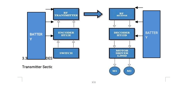
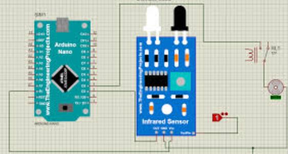
METHODOLOGY 3.1 INTRODUCTION In this project we are designing an RF remote control. For that we are using an ASK transmitter receiver module. Microcontroller is avoided in the circuit to make it cost effective. ASK module is used as the remote transmitter, two IC’s HT12E and HT12D is used for Encoding and Decoding. Circuit diagram and circuit explanation given below will help the reader to understand how a remote control car. 3.2 BLOCK DIAGRAM OF REMOTE CONTROL CAR Before carrying out any project, the block diagram must be drawn and fully understood. Block diagram gives a pictorial understanding of any work. The block diagram of the system is as below:
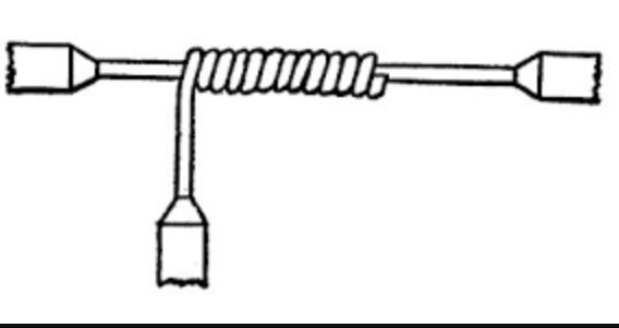
Block diagram of remote control car
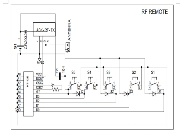
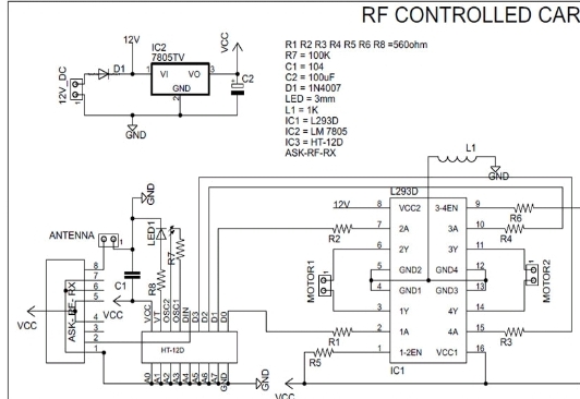
3.3 BLOCK DESCRIPTION Transmitter Section: Controlling Switches: Four button switches are used in the remote control to move the car backward, forward, left and right. HT12E Encoder IC: It is a 212 series encoder IC used for wireless communication applications. It is mainly used to convert 12 bit parallel data (8 address bits and 4 data bits) to serial out so that it can be transmitted using a transmitter Module. RF Tx Module: 434 MHz ASK transmitter module for transmission. It is capable of providing a data rate of about 8kbps. Battery: 3V button cell is used to power the remote. Receiver Section: RF Rx Module: A high sensitivity 434 MHz ASK Receiver module for receiving the data from remote control. HT12D Decoder IC: It is a 1212 series decoder IC used for wireless communication applications. It converts the serial input to parallel out. Motor Driver: L293D motor driver is used to drive two motors. L293D provides bidirectional drive current up to 600mA at voltages from 4.5V to 36V. Motors: Here two BO motors are used which are driven by the motor driver L293D and both of them are connected to robotic wheels to move the car. Battery: Receiver section need more power than the remote control circuit. So 9V/12V battery is required to power the circuit. 3.4 ELECTRONIC COMPONENTS USED Only basic electronic components were used here for the project. All datasheets and link to buy the components online are provided below: Resistor: 1K Resistor: 8 Semiconductors: HT12E Encoder IC: 1 HT12D Decoder IC: 1 Modules: ASK RF Transmitter: 1 ASK RF Receiver: 1 L293D Motor Driver: 1 Miscellaneous: 3V Button Cell with holder (Remote): 1 9V/12V Battery with holder (Receiver/Car): 1 Button Switch: 4 BO Motor: 2 Robotic Wheels: 4 3.5 CIRCUIT DESIGN OF REMOTE CONTROL CAR The circuit diagram of the device is as below:
RF remote for car
Rc car circuit diagram with remote control
RC car circuit diagram with remote transmitter Circuit design of this remote control car is simple and is of low cost as we are not using a microcontroller in it. Main components are two communication ICs (HT12D and HT12E) and an ASK RF transmitter receiver module. RC car circuit diagram with remote transmitter is designed in a compact way to make it as small as possible. Remote uses four button switches (S1, S2, S3, and S4) to control the toy. Digital data’s from the switches are encoded by the HT12E encoder IC and are transmitted to the receiver through ASK RF Module. When we press these switches, 4 data bits and 8 address bits are serially encoded and output through the pin “DOUT” is given to the 434 MHz Transmitter. Circuit is so simple due to the simple coupling of ASK module with HT12E and HT12D pair. Remote control is power by a 3V button cell. Receiver section receives the signal with the help of 434 MHz ASK module and provides it to the decoder IC. “DIN” pin of HT12D gets the data from RF module and checks it three times before decoding. And if received address data matches with the encoder address data, then IC will decode the data bits and provides it directly to L293D motor driver. This driver is used to control the motors forward and backward according to the received signal. An LED is connected to the valid transmit pin of Decoder IC to indicate a valid transmission. Left Motor Direction Right Motor Direction Direction of Car
LEFT MOTOR DIRECTION
RIGHT MOTOR DIRECTION
DIRECTION OF CAR
forward
forward
forward
forward
Backward
right
backward
forward
left
backward
backward
backward
RC car table diagram with direction
CHAPTER FOUR
4.0 RESULT ANALYSIS 4.1 CONSTRUCTION PROCEDURE In building this project, the following procedures were properly considered, I. Purposing of the entire materials / Components needed ii. Resistance check of the components bought with the help of ohmmeter before making the necessary connection with the components iii. Drafting out a schematic diagram or how to arrange the materials / components. iv. Testing the completed system to see if the design works and v. Finally, implementation of design of the project. Having procured all the materials, I processed into the arrangement of the components into the Vero board but we could not laid the ics directly on the bread board because the heat soldering iron emits while soldering, proper soldering of the components then followed. The components were all soldered into the board after which it was correctly confirmed done. 4.2 ASSEMBLING OF SECTIONS Having provided the casing and having finished the construction of the sections of this system, the assembling into the casing followed. The sections were properly laid out and assembled into the casing where the general coupling and linkages into the peripheral devices took place. 4.3 MOUNTING PROCEDURE The transformer was bolted directly to the bottom of the case. This was followed by mounting of the power section of the circuit board. A gap was made between one mounting and the successive ones. This is necessary to avoid overcrowding. The vero board is also mounted at the upper side of the case. The resistors, transistors, and other components used were mounted on the vero board. All the accessories were highly fixed to avoid slack that may result in the process of operations 4.4 TESTING After implementing the circuit on a project board, the different sections of the complete system were tested to ensure that they were in good operating condition. The continuity test carried out is to ensure that the circuit or components are properly linked together. This test was carried out before power was supplied to the circuit. Finally, after troubleshooting has been done on the whole circuit, power was supplied to the circuit. Visual troubleshooting was also carried out at this stage to ensure that the components do not burn out. 4.5 RESULT The results obtained during the construction states after necessary troubleshooting were satisfactory. The system was able to respond to its operation. 4.6 ECONOMIC OF THE PROJECT Although this project has not been given due recognition by the authority concerned, whenever this equipment finds its use the case is relatively cheap with a good efficiency and improves on its reliability. Due attention will be given to the viability of this project reliability maintainability and also the evaluation. 4.7 RELIABILITY In the design of the remote control motor car with bidirectional rotation, reliability is taken into consideration to improve on the system performance. Here the concept of reliability has been associated, in a qualitative way with good design endurance consistence quality and dependability in recent years however, the much greater complexity of the line selector and the seriousness of a failure in the system have made it necessary to attempt not only to improve the reliability of the equipment but also to assesses it in qualitative terms. In order to appreciate some of the difficulties which are involved in the designed of this project, imagine a discussion concerning the relative merits of remote control motor car in the first place the specifications of the picture quality and staying. The discussion may then turn to the likelihood of faults developing in the sets. This is important not only because of the annoyance caused to the viewer by a failure but pay a higher initial cost for an automatic change over switch in return for an assurance that the extra cost will mean smaller maintenance costs. Therefore, from this little explanation, “Reliability can be defined as the characteristics of a component or of a system which may be expressed by the probability that it will perform a required function under started conditions for a specified period of time. 4.8 MAINTAINABILITY In this design and construction of this project (remote control motor car), it is usually very important to note that maintainability is another area or aspect taken into consideration since high initial or production cost will lead to a low maintenance cost. The remote control motor car has a high input output-performance, but relatively cheap, easy and low maintenance cost. Therefore maintainability of the probability that a device will be restored to operational effectiveness within a given period of time when the maintenance action as performance in accordance with prescribed procedures”. 4.9 PROJECT EVALUATION Considering the cost of this project one must note that fact that it is not mass production. As such to single handedly manufacture it without any industrial aided production machine will in no doubt in our much expenses, the initial market survey did not prove successful due to irregular price of item such as those used in this project. 4.10 BILL OF ENGINEERING MEASUREMENTS AND EVALUATION The expenditure made in purchasing all the components / materials and quantity used in building this project is tabulated as show below.
CHAPTER FIVE
5.1 CONCLUSION In this work, remote controlled motor car was implemented. The proposed system was built and a satisfactory result was achieved. Controller executes the load to rotate “FORWARD” and “REVERSE” direction depending upon the input we are giving the virtual terminal via the remote.
5.2 RECOMMENDATIONS The device has been designed, tested and system was able to respond to its operation. This work was built with quality wiring and contains many connections, I recommend that if failure occur, it should be troubleshoot by a qualify personnel along with the circuits diagram. This project was built for Educational purposes. If one wants to use it for industrial or home applications, I recommend that a hook should be attached to the casing that would allow fixing the system on the wall. Working on this topic as my project is a good idea and it comes at the right time. I am suggesting that this particular topic should also be given to other students both in higher and lower class.
REFERENCES
[1] IIT BOMBAY, TECHFEST 2010-11, PDF’s. [2] http://www.meadinfo.org/2009/07/design-and-fabrication-of-icengine. html [3] https://en.wikipedia.org/wiki/Radio-controlled_car [4] http://www.rcuniverse.com/forum/forum.php [5] http://www.rc-help.com/forum.php [6] http://www.rctech.net/forum/ [7] Y. Ege , M. G. Sensoy , O. Kalender , S. Nazlibilek , H. Citak, J. Mesurement 46 (2013) [8] A. A. F. Nassiraei , K Ishii, Concept of Intelligent Mechanical Design for Mobile Robots J. Bion. Engg 4 (2007) [9] G. Yasuda, Distributed Autonomous Control of Modular Robot Systems Using Parallel Programming, J. Mat. Proc. Tech. 141 (2003) [10] S. Dearden, Develop Large-Scale Embedded Designs, Electron Des.40 (1992)
[11] https://maker.pro/pcb/projects/remote-control-car
[12] https://www.google.com/amp/s/www.instructables.com/How-to-Make-a-Remote-Control-Car/%3famp_page=true#cobssid=s
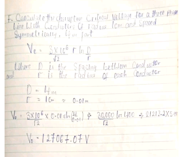
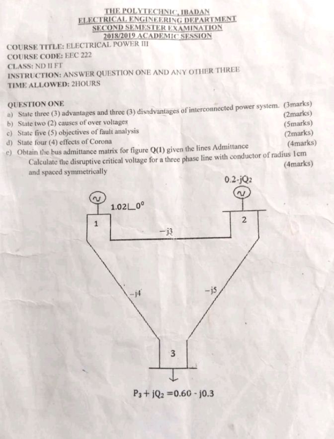
Calculate the disruptive critical voltage for a three phase line with conductor of radius 1cm and spaced symmetrically, 4m apart
Vc = (3 × 10⁶)/√2 • r × inD/r
where D is the spacing Conductor
and r is the radius of each conductor
D = 4m, r = 1cm ≈ 0.01m
Vo = (3 × 10⁶)/√2 • 0.01 × in(4/0.01)
30,000/√2in400 = 21213.2×5.99
Vo = 127067.07v
2. State three (3) characteristics of fuse element I. Low melting point e.g tin II. High conductivity e.g copper C. Low cost e.g lead
Define circuit breaker and state four types of circuit breaker Circuit breaker is a piece of equipment which can make or break a circuit manually or by remote control under normal condition B. State four types of circuit breaker I. Oil circuit breaker B. Gas circuit breaker III. Miniature circuit breaker IV. Air circuit breaker
C. State four (4) differences between fuse and circuit breaker
Fuse only work in one time and the element will be replaced Circuit breaker work over and over again
Fuse time operation is about 0.02secs Circuit breaker time operation is about 0.5secs
Fuse element can be tempered with when replacing Circuit breaker can’t be tempered with
Fuse element are always replaced after operation Circuit breaker don’t need replacement
List four types of insulators and sketch any one(1) 1) Pin type insulator 2) Suspension type insulator 3) shackle insulator
Write short note on insulating material Insulating materials are the material which do not allow electric energy to pass through them. They’re also used on electric poles for supporting and separating the conductor on the pole. Examples of insulating material I. Dry wood II. Glass III. Porcelain
Explain the difference between feeders, distributor and service mains I. Feeder: is a device that serve as a protection for the transformer and distribution line. II. Distribution mains: This is the transmission line that comes out of the transformer usually on low tension poles and carry a voltage between 220v – 414v III. Service mains: This is the mains which is used to tap from the distribution mains to the end users.
Define protective relay and draw a typical relay circuit PROTECTIVE RELAY: is a system used in protecting an electric circuit
B) List and briefly explain four (4) requirement for power system protection. I. Reliable, II. Stable, III. It must be timely, IV. It must be selective I. Reliable: The protection system must provide it function when required to avoid damage of equipment, life and property II. Stable: The protection system must not react to fault in neighbouring zone and shall not react to non fault situation III. It must be timely: The rate at which protecting system will react to fault must be fast as possible in other to stabilise the overall power system and to reduce the damage of life and property IV. It must be selective: only the affected point of the power system will be disconnected C) State the purpose of protection system I. To protect equipment II. To protect against overload III. To improve system stability IV. To restore number of direction V. To protect life and property VI. To separate faulty section from power supply D) List four (4) types of protection by object I. Line protection II. Transformer protection III. Generator protection IV. Earth protection
What is receptacle and Block diagram in Electrical graphics
What is receptacle in electrical graphics: Receptacle is an opening of series of opening connected to a wired power source that is supposed to power electrical components and equipment. BLOCK DIAGRAM: Is a kind of electrical drawing that represent the principle components of a complex system in the form of block interconnected by lines that represent their relation. Block diagram is a diagram of system in which the principle parts or functions are represented by blocks connected by line that show the relationship on the blocks.
What’s relay and DPDT
(I)RELAY: A relay is an electrical operated switch. For example a 9v battery circuit connected to the coil, can switch 230v A.C mains circuit.
A Relay: is an electrical operated switch. It consists of a set of input terminals for a single or multiple control signal and a set of operating contact terminals. The switch may have any number of contact terminals. The switch may have any number of contacts in multiple forms. Such as Make contact, break contact or the combination of the two.What is Graphics symbols: A graphic symbol is a visually perceptible figure with a particular meaning used to transmit information independently of language.
(II) DPDT→ Double pole double throw. This switch can be wired upon as a reversing switch for a motor. Some DPDT have a central off position.
SEMICONDUCTORS: semiconductor materials are partially conductor or insulator of electricity. They are material that conducts electricity but offer opposition to the flow of current. Give the meaning of the following
What is a TRANSFORMER
Transformer can be defined as a component for reducing or increasing the voltage of an alternate current Transformer is a device that transfer electric energy from one alternating current to one or more circuit either increasing/stepping up or reducing/stepping down voltage
Give short definition of the following; resistor, transistor, capacitor, diode, wire, cell and motor
Resistor : it is a device that obstruct the flow of electricity passing through a conductor. For example to limit a current passing through a LED, a resistor is used with capacitor in timing circuit.
Transistor: Is a device that aids in amplifying current
Capacitor: this are device that stores charge
Diode: This is a sensitive electronic components which allows current to pass in only one direction. It has two lead namely cathode and anode.
Wire: it serves as an entrance to pass electricity easily from one place to another.
Cell: it supply electrical energy
Motor: A transistor which convert electrical energy to kinetic energy
Four service methods that can be used to detect faults in electronics equipment. ( 2 marks)
(1) CIRCUIT TRACING
A. Know/study mode of operation.
B. To find out the fault.
(2) Troubleshooting
(3) Fault isolating
(4) Observation test method [ 2 marks]
EXPLAIN TWO OF THE METHODS LISTED IN QUESTION ABOVE
(1) CIRCUIT TRACING: are split into two;
(a) Know/study mode of operation – To be able to know the general mode of operation, sequential operation of each point, the regular noise from the machine, normal working temperature and normal range of the regulating or measuring instrument.
(b) To find out the fault – This is always cumbersome, tiring and time wasting doing it physically.
(2) TROUBLESHOOTING: This is a method where by fault is purposely introduce into a system in order to watch the behavior under a faulty condition. It might be by;
(I) removal of part
(Ii) disconnecting a link
(III) short-circuiting some points
(IV) connecting a live terminal to the earth.
This method will help in knowing how to Carry out repairs or replacement of bad points. It helps to predict the symptoms and signs of a fault.
(3) FAULT ISOLATING: A fault circuit is disconnected from the rest of the system in order to carry out repair services. If possible other parts may continue to function.
(4) OBSERVATION TEST METHOD: consist of the following;
(a) VISUAL— ( sense of sight): To detect loose live terminal, burnt resistor or blown fuse which are indication of overload, short circuit or earth fault.
(b) TOUCH — feeling: By placing ones finger or palm can make one to know whether there’s a rise in temperature, vibration or humming.
c) SMELL — To enable one to know burnt or overheating.
d) HEARING — sound coming from a machine can enable one to suspect or know the type of fault or an unusual sound/humming.
WHAT’S THE FUNCTION OF FOCUS ADJUSTMENT AND ELECTROSTATIC FOCUSING IN MONOCHROME TV
The domestic television receiver is required to receive signal over a wide bandwidth and is based on the superheterodyne principle. The television receiver is more complicated than a broadcast radio receiver because the former is required to reproduce a video signal, synchronized scanning waveform for the CRT and sound signal
THE BLOCK DIAGRAM OF A TYPICAL MONOCHROME RECEIVER.
1) FOCUS ADJUSTMENT: The focus adjustment is the electron beam. The electron beam must be focused to small ports/spot light on the screen usually focus is sharp on the center area of a tube. FUNCTION: Older picture used in magnetic focusing with a focused signal on the neck of the tube behind the deflection yoke.
2) ELECTROSTATIC FOCUSING: Is omitted from a cathode tends to diverge because they repel each other. However the electron can be forced to converge to a point by an electric or to a magnetic field. So the voltage focused in the beam to a spot is called a crossed point beyond the control grid.
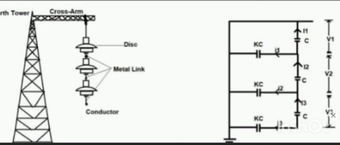
1 PIN TYPE INSULATOR: Are made in piece up to 25KV and above for up to 50KV only. You can add up the voltage by adding one more piece, they become uneconomical for higher voltage.
2. SUSPENSION TYPE INSULATOR: Are made in form of disc and a number of them used in a flexible string for the voltage range desires with the conductor being attached to the lower end for 400KV lines, 19 discs of overall length 3.84m are used.
3 STRAIN TYPE INSULATOR: Are obtained often a string of suspension insulator is used in a horizontal position. They are mainly used in line terminal and crossed end roads.
An autotransformer is supplied at 240V. If the secondary is tapped to give 60V with a load current of 12A, calculate the other two circuit currents and show the direction of current and voltages (5 marks)
The four parameters that determine the performance of a transmission line is conductance, resistance, inductance and capacitance.
RESISTANCE: Resistance is stated in ohms per meter length of a line and its represent the imperfection of a line. In other words, it obstruct or resist the flow of current in a circuit. It’s measured in ohms [Ω]
CAPACITANCE: It is the ratio of the charge on one plate of a capacitor to the voltage difference between the two plates. Its measured in farads [F]. Or it can be define as the ability of a capacitor to store charge.
INDUCTANCE: Is a property in which an inductor, exhibit an opposition to the current flowing through it. Or it can be define as the process in which an E.M.F is produce to oppose the current flowing through it. It’s measured in henry [H]
CONDUCTANCE: It is an ability of an element to conduct electric current, it is measured in siemens[S]
list five (3) advantages and three (3) disadvantages of a hydro power plant.
Answers (1) Renewable: hydro-electric energy is renewable, that means hydro-electric energy can be generated again after been used up.
However, there’s only a limited number of suitable reservoirs where hydro-electric power plants can be built and even less places where such projects are profitable. Pollution free: it is clean and good. There is no pollution at all.
(2) Reliable: it is very reliable because it has sufficient energy. A house, shop or industry can use once there is sufficient water in the dam.
(3) Flexible: hydro-electric power can be tapped or taken to different households or without difficulty and adjusting water flow and output of electricity is easy. Safe: compared to among others, fossil fuel and nuclear energy, hydro-electricity is much safer.
Disadvantages (1) It involves high capital cost due to construction of dam. (2) There is uncertainty about the availability of huge amount of water due to dependence on weather condition. (3) Skilled and experienced hands are required to build the plant. (4) It requires high cost of transmission lines as the plants is located in hilly areas which are far away from the consumer.
Nuclear power station
A generating station in which nuclear energy is converted into electrical energy is known as a nuclear power station. Advantages of nuclear power station. Mention seven (7) (1) It ensures reliability of operation.
(2) There are large deposits of nuclear fuels that can ensure the continuity of electrical energy for thousands of years are available all over the world.
(3) It can be located near the load centers because it does not require large quantities of water and need not be near coal mines. And therefore, the cost of primary distribution is reduced.
(4) This type of plant is very economical for producing bulk electric power.
(5) It has low running charges as a small amount of fuel is used for producing bulk electrical power.
(6) A nuclear power requires less space as compared to any other type of power station.
(7) The amount of fuel required is small. Disadvantages (1) The fission by-products are generally radioactive and may cause a dangerous amount of radioactive pollution.
(2) The erection and commissioning of the plant requires greater technical know-how.
(3)The capital cost on a nuclear plant is very high as compared to other type of plants.
(4) The fuel used is cost and is difficult to renew/recover.
WAN]:Wide area networking combines multiple LANs that are geographically separate. This is accomplished by connecting the different LANs using services such as dedicated leased phone lines, dial-up phone line (both synchronous and asynchronous), satellite link, and data packet carrier services. It can be as simple as a modem and remote access server for employees to dial into, or it can be as complex using special routing protocols and filters to minimize the expense of sending data sent over vast distances.
METROPOLITAN AREANETWORK
MAN consists of a computer network across an entire city college campus or small region. A MAN is larger than a LAN. Depending on the configuration, this type of network can cover an area from miles to tens of miles. A MAN is often used to convert several LANs together to form a bigger network. It is specifically designed for security purpose.
VIRTUAL PRIVATE Network
[VPN]: VPN is a technology that allows a network administrator to create a secure connection over a loss-secure network between computer and the internet. It protects information privacy by allowing the administrator to anonymously appear to be in any network. A VPN is beneficial because it guarantees an appropriate level of security and privacy to the connected systems. This is extremely useful when the existing network infrastructure alone cannot support it.
Signals is a physical quantity or an electrical waveform that carries information. It can also be define as a pattern, or changes that convey information from a source to a destination. The purpose of a signal is to transmit this information timely and accurately. Signal is a physical and electrical representation of information that is used to transmit data in various communication system.
Type of signal
Analog signals: They are continuous waveforms that vary in time and amplitude
Digital signals: They are not continuous wave but are discrete in nature i.e their values are typically binary digits (bit) a “0” and a “1”
Characteristics/properties of signals
Amplitude: These refers to the magnitude or strength of the signals
Frequency: is the number of cycles or oscillation that occurs within a given time period. Measured in hertz (Hz)
Phase: Refers to the relative positioning or timing of a signal waveform with respect to a reference
Duration: Represent the length of time that a signal persist or exist.
Periodicity: Refers to whether a signal exhibits a repetitive pattern or not.
Symmetry: These describe the balance or distribution of a signal waveform
Bandwidth: it refers to the range of frequency that signal occupies or occupies for transmission
Energy and power: are measures of the total or average amount of signal energy overtime. Energy is related to the finite duration of a signal while power is the energy per unit time
Example of analog signals
Audio signal: In electronics, an audio signal generator is a piece of electronic test equipment that generates electrical signals in the audio frequency range. These signals are usually created using a voltage-controlled oscillator or a pulse train and then route to an amplifier before being sent to the loudspeakers, whose output makes up the desired sound.
Electromagnetic waves: The electromagnetic waves consist of both electric and magnetic fields. Electromagnetic waves can travel long distances in space. The electromagnetic signals are also called radio frequency (RF) waves
Voltage signal: a voltage signal refers to an electrical signal that varies in voltage, typically measured in volts. Voltage signals are often used to represent analog data such as sound, temperature, and light intensity
Application of analog signals ( where we can find it)
Analog telephone
AM/FM radio
Television broadcasting
Note: that analog signals are susceptible (likely or affected) to noise and distortion during transmission, which can degrade the quantity of the received signal.
Advantages of digital signals
Immunity to noise ( insusceptible)
Better signal quantity
Efficient use of bandwidth
Digital Modulation
It is the whole process of modifying a digital signal to enable it to be transmitted over a communication channel.
Digital modulation techniques
Amplitude shift keying (ASK): In ASK the amplitude of the common signal varied to represent digital “1s” and “0s“
Frequency shift keying (FSK): It involves shifting the frequency of the carrier signal between two or more predefine frequencies to represent different digital symbols. For example, if we have two sine waves with different frequencies but equal amplitudes, they would be indistinguishable on an oscilloscope unless we normalized their amplitudes first. If you multiply each frequency by its corresponding normalized amplitude measurement, you can use frequency as an independent variable.
Phase shift keying (PSK): It changes the phase of the carrier signals to represents digital symbols ( 00, 900, 1800, 2900 )
Quadrature amplitude modulation (QAM): Is a complex modulation scheme that combines amplitude and phase modulation. (QAM represents digital data in varying both the amplitude and phase of the carrier)
Quadrature phase shift keying (QPSK): is a modulation scheme that allows one symbol to transfer two bits of data. There are four possible two-bit numbers (00, 01, 10, 11), and consequently we need four phase offsets. Again, we want maximum separation between the phase options, which in this case is 90°
Orthogonal frequency division multiplexing (OFDM): Orthogonal frequency division multiplexing (OFDM) takes a digital information signal with bit rate Rb, maps n-bit words on to M = 2n symbols (each symbol being a complex number representing the amplitude and phase of an M-ary modulation scheme), splits the resulting symbol stream (rate Rs = Rb/n) into N parallel streams (each with rate ROFDM = Rs/N) and modulates each stream onto one of N different carriers [12]. The N frequencies chosen for the carriers are such that the carriers are mutually orthogonal over one OFDM symbol period, TOFDM = 1/ROFDM, allowing independent recovery of each parallel information stream.
Digital modulation principle
Pulse amplitude modulation (PAM): Converts a discrete time signal into a variable amplitude continuous time signal that is good for high-speed wired communication system.
Pulse position modulation (PPM): Is a modulation method that only makes every pulse in the carrier pulse sequence change within time but without changing shape and amplitude of pulse signal.
Pulse Code modulation (PCM): is a digital scheme for transmitting analog data. It converts an analog signal into digital form. Using PCM, it is possible to digitize all forms of analog data, including full-motion video, voice, music, telemetry, etc.
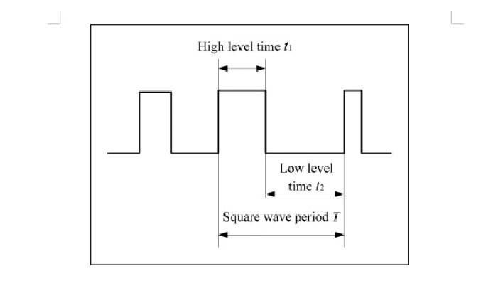
Pulse Width modulation (PWM): is a modulation technique that generates variable-width pulses to represent the amplitude of an analog input signal. The output switching transistor is on more of the time for a high-amplitude signal and off more of the time for a low-amplitude signal.
This entails a quick Question & Answer summary of what Drafting and design course is all about in electrical engineering. As a student who’s interested in Drafting and design course, it’s advisable you go through this.
1. List three(3) types of connection diagram in an electrical design
Block diagram
Wiring diagram
Schematic diagram
Write short note on each types of connection diagram
Block diagram: is a symbolic representation of a working process, production line or even it can be used to represent a system of government activities.
Schematic diagram: it is a standard name used for a circuit diagram. It can be defined as a diagram that utilizes a circuit symbol to show the interconnection and function of a component that makes up of a circuit diagram of a system.
A wiring diagram: shows the relative layout of the components and the wire connections between them. This type of diagram shows the physical relation of all devices in the system, the conductor terminations between these devices, and are commonly used in motor control installations
B. state four(4) classification of lighting scheme
Direct lighting scheme
Indirect lighting scheme
Semi-direct lighting scheme
Semi-indirect lighting scheme
Direct lighting schemes: By this method most of the lighting scheme is made available on the working surface and very few percent is wasted. Light shining onto an object is called direct lighting. It determines the color and quantity of light that reaches a surface from a light source, but ignores all light that may arrive at the surface from any other sources, such as after reflection or refraction.
Indirect lighting scheme: The light does not reach the working surface directly. Uses one or more fixtures to aim light onto the ceiling and upper walls, which act as reflectors and distribute the light evenly throughout the room. Indirect lighting is a form of ambient lighting.
Semi-direct lighting scheme: In this scheme about 60 to 90% of total light flux is made to fall on the working surface and 10 to 40% is allowed to fall on the ceilings and walls. This is achieved by providing semi-direct reflectors. Such a scheme is best suited to rooms having bigger height
Semi-indirect lighting scheme: In this system 60 to 90% of the total light flux is diverted to fall on the ceiling from where the light is directed on the working surface by diffused reflection. Only 30 to 40% flux reaches the working surface.
C. Write short notes on each of the following; cosine law, inverse square law, maintenance factor and diversity factor.
Cosine law: the illumination on the surface is proportional to the cosine of the angle X between the direction of the incident light and the normal to the surface.
Inverse square law: this illumination at a point for the surface produced by light from the point of source was inversely to the square of the point of source.
Maintenance factor: it refers to the loss of light that occurs over time and is also known as loss factor. During the operating time of light sources, it can be seen as slight decrease of light output. in other words it is called lumen
Diversity factor: this is the ratio of the sum of individual demand of the various sub-division of the system to the maximum demand of the whole system under consideration.
2. Enumerate the difference between switch gear and distribution switch board
Switch gear
Switch gears protect equipment from electrical hazards or failure due to short circuit.
Switch gear finds their use in powering transformers lines, generators and power networks.
Switch gears is designed to handle voltages that can reach 350KV.
Switch gears come with automatic features and come with manual control during emergency.
Switch gear has switching device that are required for low to medium-voltage circuits.
Switch board
They are designed to handle lower voltages that are generally less than 60 volts
Switch boards don’t have any automatic features and are placed to display the amount of power consumed by individual circuits.
They consists of panel where switches, buses and electrical control devices have been mounted on the front or back end
They are only used to distribute power to multiple sources and transmit them to individual loads, transformers, panel boards and control equipment.
They have fixed mount circuit breakers that are connected directly to bus bar.
B. State four(4) factors to be considered when selecting a consumer unit for an installation.
Number of circuits
Type of circuits
Brand and model
Price
C. Explain briefly the difference between domestic premises and non-domestic premises and state the types of supplies which are taken to each of the premises stated above
Domestic premises are residential wiring that run through walls in a single phase design and it uses less voltage due to lower electrical load.
Non-domestic premises are industrial wiring that uses a three-phase design to create higher output to power higher voltage equipment and multiple systems.
Note: Domestic premises make use of 230/240V while non-domestic premises make use of 11/33KV
3. Explain briefly the term stroboscopic effect on rotating electrical equipment.
Stroboscopic effect is the phenomenon which makes moving objects like fan blades to appear to be stand still and a wave of the hand to appear as if it occured in a series of jump.
State two(2) methods to be adopted so as to reduce stroboscopic effect
Using three lambs on the separate phase of 3-phase supply: when three(3) phase supply is used in the industry the adjacent fluorescent lamps should be fed with different phases so that the zero crossing of the two lambs will not be the same.
Reducing the level of TLMs: design of lighting equipment to reduce the TLMs of the light sources is typically a trade off for other product properties and generally increases cost and size, shortens lifetime or lower energy efficiency.
What are the different special purpose of transformer?
You can use transformer as;
Regulating transformers
Converter transformer
Rectifier transformer
Mining transformer
Welding transformer
What is reactor?
Reactors are equipment of transformer family. Reactors are used in the power system(network) for current limiting and for compensation of reactive power.
Types of reactors
Series reactor: are necessary for limiting short-circuit currents, for limiting rush currents while switching-in for limiting current surges with fluctuating loads, for smoothing the current wavesform, etc.
Shunt reactor: are necessary for shunt harmonic filter and for providing reactive power compensation for long AC lines.
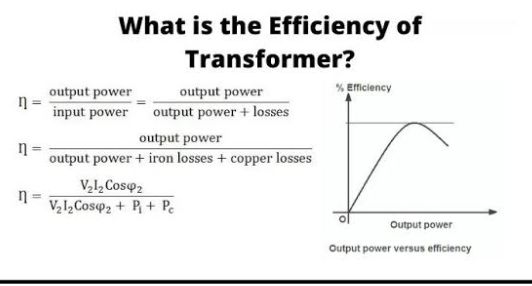
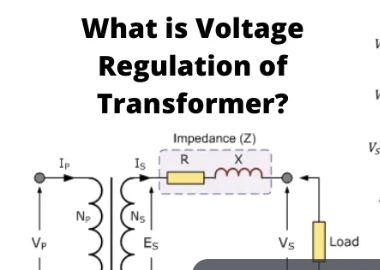
What is transformer?
Transformer is a static electrical equipment which transformer are electrical power from one voltage to another voltage at some frequency by electromagnetic induction. The transformer design, manufacturing and testing techniques have advanced with following objectives;
High efficiency
Low material cost, smaller size
High reliability, long life, low maintenance.
Low noise
To conform to relevant specifications.
Important advances in power transformer technologies includes;
Improved magnetic materials for core
Lower losses
Reduced size of core
2. Improved method of construction of core
Elimination of core bolts
Use of mired joint between laminations of leg and yoke.
3. Improved conductors and conductor insulators: multiple wire transposed conductors are now used, thereby the eddy current losses and skin effects are reduced.
4. Reduction in Noise: use of superior magnetic sheet steel, improved method construction of core and tank.
5. Improved design of windings and insulating system: The distribution of electrical stresses between winding and core, windings, turns of a winding, coils of a winding depends on electromagnetic phenomena,.
Types of transformer
Core type transformer: A transformer on which the windings surrounded the limbs of the core.
Shell type transformer: A transformer in which the core surrounds major portion of the windings.
Principle of operation of transformer
A transformer has two or more separate winding placed on a common magnetic core. It works on induction principle. The primary winding is supplied with alternating current of supply frequency. Thereby alternating magnetic flux of the same frequency is produced in the magnetic core.
What is testing in transformer?
Testing: is to ensure good health of transformer and trouble-free service
Kinds of test on a transformer
Acceptance test: validates that your product is built and operating following design specifications and regulations. For transformers, it’s the process of testing to confirm that it meets all elements of the international standard
Type test: type test prove the capabilities and guaranteed ratings
Routine test: are conducted to verify that the manufactured and assembling are satisfactory
Special test: are conducted in testing laboratory or at site to investigate certain phenomena.
Site test: are carried out after complete installation to confirm that there are no transit damages and installation is satisfactory.
Quality checks test: these are conducted on components, sub-assembling and complete assembly to confirm that the quality is satisfactory and there are no material/manufacturing defects.
What is a substation
A substation is an assemblage of electrical apparatus. Transformer are necessary in a sub-station for stepping-up and stepping-down of voltage. Besides transformers, substations has several other electrical equipment’s including bus-bars, circuit breaker, isolators, surge arrestors, etc.
Busbars: Incoming and outgoing circuits connected to bus-bars.
Circuit breakers: Automatic switching during normal or abnormal conditions.
Insulators: Disconnection under no-load condition for safety, isolation and maintenance
Earthing switch: To discharge the voltage on dead lines to earth.
Current transformer: To step-down current for measurement, control and protection.
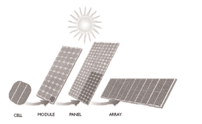
The off-grid system term states the system not relating to the gird facility. Primarily, the system which is not connected to the main electrical grid is term as off-grid PV system . Off-grid system also called standalone system or mini grid which can generate the power and run the appliances by itself. Off-grid systems are suitable for the electrification of small community. Off-grid electrification system is viable for the remote areas in the countries where they do have little or no access to the electricity because of the distinct living and spread population in the vast area. The off-grid system refers to the support that would be adequate for a living without depending on the grid or other system. Electrical energy in the off-gird system produced through the Solar photovoltaic panels needs to be stored or saved because requirement from the load can be different from the solar panel output, battery bank is also used for the purpose generally.
1.1 Background of study
Energy systems often include Renewables Energy Systems (RES). RES play an important role from technical, economic, social and environmental point of view. The high cost of the fuel used in systems based totally on diesel generators (gensets) has led to the development of hybrid energy systems. Hybrid energy systems are the combination of two or more energy sources, from Renewable Energy Technologies (RETs) and from conventional technologies, with an energy storage and power conditioning system. The use of RES would reduce the fuel consumption as well as the polluted emission of a 100% diesel plant. The initial investment will be higher in a hybrid energy system, but the use of fuel and consequently its cost will be reduced.
1.2 Statement of the problem
About 1.3 billion people worldwide have no access to electricity. Around 20 % of the total population, most of them located in rural or isolated areas have little or no access to main grid. A good development of Mini Grid systems, apart from offering reliable electricity, could also improve the economy of these areas. On the other hand, climate change implies finding new ways to obtain energy and protect the environment, renewable energy systems are escalating fast, and can lead to fight carbondioxide(CO2) emissions in a high percentage. Three important fields to consider in this study will be technical, economic and social aspects, which have to be taken into account when choosing a Mini off-Grid system implementation. Regarding the technological dimension, significant advances can be observed with these kinds of technologies. Secondly, there is a need for an affordable operation and durable system installation. Thirdly, with respect to the social dimension, a lack of communication exists between foreign companies that install the components taking part in mini-grid systems, and the locals that live in rural or isolated areas and own the land. In addition, there are some constraints when evaluating the success of the whole system installation and its performance. For instance, referring to PV and wind turbines, it is known that they do not always work at their maximum production level, since it will always depend on the daily sun radiation and wind speed. This situation could lead, in some cases, to an overuse of the diesel generator implying greater economic expenses and higher emissions. Moreover, another disadvantage related to the installation process is the difficulties that can be found in reaching isolated areas due to the existence of poor access, for example, for transportation. In summary, the current study is relevant principally to provide these communities and areas with reliable electrification; consequently, implying an improvement in their lifestyle and economy. Therefore, this document tries to explore the crucially important position of households in Mini off-Grid systems in order to achieve a better understanding and a more encompassing policy debate while taking into account the proper and most efficient use of natural resources.
1.3 Aim and Objectives of the Research:
The usage of solar energy is increasing day by day both in terms of demand and usage. Our aim is to provide the most useful solar solution while maintaining the novelty. So, the construction of a mini off-grid solar home system. Futhermore, An off grid system with DC load along battery bank. The off-grid application is considered because the system is to be independent of the grid so that it can be used at any time. The objective of this research is to provide a better understanding of the different kind of impacts the use of off-grid solar systems has upon the livelihoods of households
1.4 Contribution to knowledge
The construction of a mini off grid solar system has brought about the understanding that life can be made a lot easier with the presence of a mini off grid solar system as sun is free, sustainable, clean resources we can leverage in place of convectional electricity to power our lives. Solar energy can be used to provide heat, light and other electricity-dependent needs in homes
1.5 limitation/scope of the project
Some of the limitations of an off grid mini home solar system include;
They are more costly
batteries are required to deliver electricity consistently throughout the day and night
it could require a lifestyle change to reduce energy consumption
surplus energy production
cannot rely on the grid at night or on cloudy days
batteries require maintenance, have a relatively short lifespan and degrade rapidly
CHAPTEER TWO 2.0 LITERATURE REVIEW
2.1 Brief outline of the project
2.2 Historical background of the project
The term off grid first appeared in the mid nineties, highlighted by the environmental nick Rosen in the launch of an ecological motivated website www.offgrid,net and featured more recently in his book how to live off grid (Doubleday 2007) The history of solar energy Thinking of solar energy in the 21st century,a smart system of powering our homes with the light from the sun and solar panels. While solar panel technology is relatively new, dating back about 50 years, the use of suns energy to sustain livelihoods in fact began a number of centuries ago. History with the sun has a far dating and fascinating history, documented from as far as the 7th century B.C . Societies, throughout time, have been using the suns energy in intelligent ways to facilitate their lives. From the discovery of fire to the vast commercialization of solar power and domestic usage in todays world. The solar energy we have known to come and love as a renewable form of energy, has inspired some of the greatest changes in recent times . Below is the summarization of the solar energy breakthroughs from the 16th century to the present day Ancient uses of solar energy Early uses of the sun focused on harnessing the sun’s energy for use as a heat source. Dating back to the Ancient Egyptian civilizations, buildings were designed in ways that maximized light entry and warmth. From the 3rd Century B.C., the Ancient Greeks and Romans were using sunlight to create fire torches. Proving particularly handy for sacred and religious ceremonies.
The 16th-17th century: Development of the first solar cell Fast forward to the 16th century, the first solar cell was designed by Swiss Scientist Horace-Benedict de Saussure in 1767. Seventy-two years later, further innovation and progress in the evolution of solar energy was made. At just 19 years old, French scientist Edmond Becqurel discovered the Photovoltaic Effect: voltage and electric current in materials can be generated upon exposure to light. By 1870, another milestone was reached where the discovery that light could be turned into electricity without heat is made. Moving onto the 1890s, the first commercial solar heat pump was patented. By the end of the 17th century, American inventor Charles Fritz created the first working selenium solar cell (in today’s era, silicon is used in cells for solar panels). Up until this point, the contribution and experimental discoveries of various inventors and scientists had led up to the creation of the modern solar photovoltaic (PV) panel.
Early 20th Century: The modenization of solar energy 1905 was the year a young Albert Einstein (26 years old at the time) published his work titled “On a Heuristic Viewpoint Concerning the Production and Transformation of Light.” Where he studied what became known as the photoelectric effect. 1917 Einstein gave a theoretical foundation to photovoltaics by introducing the notion that lights as packets carry electromagnetic force. By 1954, scientists at Bell Laboratories developed the first practical photovoltaic cell. By the mid 1950s the first solar-powered telephone call was made. Illustrating the further development and reliability in solar energy being recognised. A year later in 1956, the first solar powered radio was introduced by General Electric. The radio was able to function in the day and night. Just a few years later, the US experimented with the application of solar PV cells on Earth orbiting satellites. Since then and up to the present day, solar power is the accepted energy source for space applications! By 1958 a spacecraft called Vanguard I became the first to be powered by solar panels. In London 1960, the first solar car was introduced, with a solar-panel roof and a 72-volt battery. 1982 was when the first large-scale solar farm was built near Hesperia, California. Developments in solar continued throughout the 1990s, and emerging global economies began to grow their share in renewables (especially wind and solar PV) during this time. The 2000s: Solar energy goes commercial From the 2000s, solar power starts to become accessible for everyone. The renewable energy sector is booming and the following decade sees ground-breaking advancements and the expansion in solar PV tech and their installations respectively. Mandatory targets for renewable energy are now set across the EU. We see the development of a competitive internal energy market, with renewables playing an important role. From the 2000s to the 2010s, more capacity is added to the renewables sector than any other (and this trend is continuing!). In 2012, the European Photovoltaic Industry Association, stated that ‘the solar PV industry installed more than 30 gigawatts worldwide which led to the cumulative global installations to be more than 100 gigawatts.’ Solar panels become more efficient, convenient and easier to access for home and business owners. As of 2018, there were more than 1 million solar PV installations. During 2018, the UK generated 3.9% of its total electricity using solar power. 2019 saw the first offshore floating solar farm is installed in the Dutch North Sea. By 2020 it was cheaper to build a new solar plant than it is to continue operating an existing coal plant. Showing just the extent of our reliance on solar energy. By 2020 The International Energy Agency declared that “Solar is the new king of the electricity markets”. And finally, 2021 and 2022 is set to see renewable energy accounting for 90% of new power capacity expansion globally. The present day: Solar energy goes global Today, we continue to see the expansion and use of solar powered devices, infrastructure and transport. Investments into solar parks and farms (both the small and mega) continue to take place across the globe. The historic advancements and current position of solar place the power of this renewable resource in a promising position. In terms of the UK’s solar future, it looks particularly bright as it sets to double its solar capacity by 2030.
2.3 Theory and concept revelant to the study
ITEM
POWER (W)
QTY (n)
Number of hours
Energy Wh
Lightening
30
3
6
0.590
Fan
50
1
6
0.300
Television
200
1
9
1.800
Solar panel
50
1
9
0.450
Total power
330
6
30
309wh = 3.09Kwh
BEME Table 2.3 Theory and concept revelant to the study
2.3.2 Shade Analysis: Shading can be a problem for the solar panels as they decrease the maximum power that can be generated. Several factors contribute to this issue, the most common cause of shade on a solar panel are;
1) Shade from neighboring trees and buildings in vicinity,
2) typical cloudy weather, and
3) shade from adjacent solar panels.
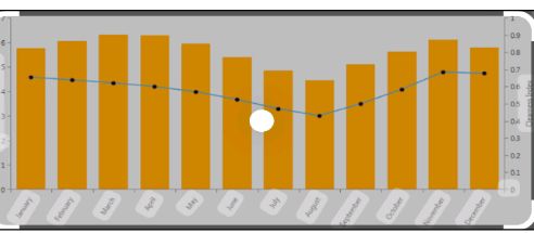
While designing a solar PV system one must investigate these factors thoroughly so that maximum output can be obtained. One of the tools most commonly used is solar pathfinder which gives the direction of the sun throughout the year and how much any specific area will receive sunlight throughout the year. Apart from having this tool, it is important that the site assessment is done properly to locate the best site keeping in mind all the aspects. Sun hours: Sun hours are important to know how much radiance will be required to generate the needed output wattage. This parameter gives us the knowledge of number of hours an area will receive maximum sunlight. With advances in technology we have this data available online and anyone can use it. We have studied the data from NREL and NASA but for our project we will be uvsing data given by NREL as it is giving information of the Sun hours to a closer proximity to Charleston. The following chart gives the required information of the Sun hours depending on different zones classified by NREL chart 2.2 Sun hours depending on different time zones
Sun hours depending on different time zones
Tilt angle: Tilt angle is the setting of the panels one needs to have to get the maximum radiance. Ideally the tilt angle is the latitude of the geographic location. It is suggested to have an adjustable panel frames as the sun hours keep changing with respect to the tilt in winters and summers. Hence for any area a specaific tilt angle is calculated to get the maximum radiance throughout the year for a fixed panel. Also, it is advised to have the panels facing the south to get the maximum afternoon sun. A couple of devices are used in the process of finding the tilt angle and the radiance that will fall upon panel at that tilt angle are inclinometer and pyrometer, respectively. An inclinometer is kept on the panel and the degrees are read to find the latitude of the area as it is perpendicular to the Sun’s radiations when it is at its highest point in the sky. Pyrometer measures the solar irradiance that will fall at a given tilt angle. It measures solar irradiance in Watts per meter Sq. 2.3.3 Battery Sizing; PV battery system assesses various strategies from a financial perspective. The valuable existence of the battery is limited to 5,000 cycles or in the planned living time of 20 years. The maintenance of photovoltaic and rechargeable annual activities and expenditure systems is set at 1.5% per the speculative cost. Assume that the cost system for the battery and PV is comparable to their size. Following is a formula that will enable to calculate what size of battery they should have. (Leonics, n.d.) Battery Capacity (Ah) = Total Watt-hours per day used by appliances x Days of autonomy (0.85 x 0.6 x nominal battery voltage) 2.3.4 Inverter: Inverter deals with following main tasks of energy: (ALTE store, n.d.) Convert DC from PV module to AC Ensure that the cycle of alternating current cycles is 60 cycles Reduce voltage variations Ensure that the condition of the AC waveform is suitable for the application Most system-connected inverters can be introduced externally, and most of the off-grid inverters are not weather-resistant. There are basically two types of grid intelligent Inverters: Those designed for batteries and those designed for systems without battery-connected inverter systems and give excellent void-quality strength. For matrix associations, the inverter should have a “useful-interactive” typeface, which is printed specifically for the publication name. Grid-connected systems measure the power of extracting PV clusters rather than a bunch of prerequisite buildings. It asserts that what each power supply needs are what the matrix-related PV system can give naturally is drawn from the net. Invertors used for solar PV systems are usually based upon the total wattage of the solar panels, as the invertor will be continuously converting the power generated. The second consideration one must investigate, is the voltage level of the system. For example, if the system is designed to generate 2000 Watts at a voltage level of 12 V then the invertor selected should be rated 12V, 2000 Watts (Alternative Energy, n.d.). 2.3.5 Charge Controller: The charge controller, sometimes referred to as a photovoltaic controller or charger, is only necessary for the system which involves a battery (Wholesale Solar, n.d.). The main capacity of the charge controller is to counteract the battery spoofing. The basic function of charge controller is to monitor charging and discharging of the battery. It prevents the battery from being completely charged or discharged. This is important because over charging can lead to destruction of the battery and under charging decreases the battery life. Another important reason to use a charge controller is to prevent a reverse current flowing from battery to the system. There are two types of controllers that are widely available in the market; 1) Pulse width Modulation (PWM), 2) Maximum Power Point Tracking (MPPT) (Northern Arizon Wind and Sun, n.d.) 1. Pulse width modulation: A pulse width modulation charge controller is set match the input power of the battery irrespective of the power generated by the panels. There is an inherent loss in power observed in this type of charger. 2. Maximum Power Point Tracking (MPPT): This type of charger helps to get the optimum charging power for any given point of time and offers better efficiency that PWM. Though the MPPT charge controllers enable you to have better efficiencies and provides more power than compared to PWM for similar condition, the main cause of not opting for MPPT is price of it (Solar Guy, 2016). MPPT charge controllers are more expensive than PWM controllers. Keeping this parameter in mind, this project will be using a PWM charge controller for realizing the concept. To select the size of charge controller one must know the voltage level of the system and the maximum operating current. It is a usual practice to over size the controller for safety reasons. Proposal to Convert 7th Street Bus Stand into a Standalone PV System Bus shelters are common in every structure one can find in urban and sub-urban settings and most of them are tied to the grid to provide electricity. But most of the rural and sub-urban areas do not have this facility of having their bus shelters electrified through grid. In such place we could use the off-grid or standalone PV system which can function without the grids assistance. Eastern Illinois University has always been a leader in embracing new technologies that promotes betterment of the environment and its students. Panther shuttle bus-stops across the campus serve hundreds of the students on a day-to-day basis. Currently, all the bus stops on the campus are not connected with the existing electrical grid. Hence, taking an initiative to serve the students an also realizing a proof of concept for standalone systems the following PV system has been designed.
1.0 INTRODUCTION 1.1 BACKGROUND OF THE STUDY With the rising need of electricity in its efficient, less toxic, consistent and cheapest form, there is need to explore every means of satisfying the aforementioned needs and solar electricity has been one of the leading ways to achieving that. Solar electricity provide consistent and steady source of solar power throughout the year. The main benefit of solar energy is that it can be easily deployed by both home and business users as it does not require a huge setup. Solar energy not only benefits individual owners, but also benefit environment as well. It is non-polluting as it does not release harmful gases like carbon dioxide, nitrogen oxide, or sulphur oxide. Solar energy requires low maintenance, does not create noise, is easy to install and can be used in remote locations. Solar electricity is one of the most widely used renewable energy source.
Solar battery
Solar energy is energy that comes directly from the sun. The sun is a constant natural source of heat and light, and its radiation can be converted to electricity. This source will last for at least a billion years (Royal Swedish Academy of Sciences, 2010). First photovoltaic (PV) solar panels have been designed and used mainly in space technologies, as the production costs of such panels were very high. As the time passes, the photovoltaic cells can be produced cheaper and cheaper and their efficiency is rising (Nese and Grenci, 2011). This is also a reason why they are being used much more frequently and it is not rare to see them on the rooftops any more. The future offers even bigger possibilities, as new thin plastic solar cells are being developed with prospects of cheap large scale production using printing technology (William T. et al., 2010). Photovoltaic solar systems can be divided into two basic categories grid connected and off-grid(also stand alone or isolated) solar systems. The grid connected systems feed the electricity produced by solar panels to the grid using an inverter. When the electricity is needed during night or periods with little sunlight, the energy is taken back from grid (AlekIndra, 2011). In isolated systems, the excess electricity is usually stored in batteries during the day and batteries are used to power the appliances in times when photovoltaic panels do not produce enough energy. A photovoltaic (PV) system may be a combination of several components such as a battery system, DC/AC conversion circuits and other power conditioning devices, in addition to the solar panels themselves (Piao, Z.G. et al., 2005). A lead-acid battery is an electrical storage device that uses a reversible chemical reaction to store energy. Using lead-acid battery charge can be stored more swiftly by grid connected system. A dc chopper converts directly from dc to dc and is also known as a dc-to-dc converter. A dc chopper circuit can be considered as dc equivalent to a transformer with a continuously variable turn ratio. Like a transformer, it can be used to step-down or step-up a dc voltage source. Here a dc-to-dc converter is used to charge the battery sufficiently. The information presenting in this body of work concentrates more on the electronic means of enhancing energy efficiency in a PV system as well as describing energy storage and power grid integration techniques. This branch of power electronics is generally called power conditioning and in the present case is used to describe the management of electrical energy to effectively charge batteries, draw maximum power from the solar panels or provide a high quality AC output.
1.2 STATEMENT OF THE PROBLEM Today the micro-grid for solar home system has turned out to be a very promising solution for remote places of Nigeria where the grid supply has not reached yet. In this regard our conventional solar home system charge controller is asking for a solid and innovative solution to accommodate variety of solar panels with different voltage level for micro grid. So far the solar home system charge controller we have in the present market is customized for 15V panel mostly. Looking at this problem we tried to come up with a new charge controller, based on DC to DC fly-back converter which enables the system to use any voltage level solar panel and charge the same 12V battery. One of the other important features of this charge controller is that, as it allows the system to use high voltage panel like 48V, the copper loss from panel to charge controller is much smaller compared to other system. As the charge controller remains with the battery, the panel to charge controller wire loss dominates the total system loss and therefore our proposed charge controller can make the conventional solar home system more efficient and more effective. An important aspect of the solar electricity setup is the charge controller. It is inevitable when mentioning solar electricity as it forms an integral part of the solar electricity family. A charge controller limits the rate at which electric current is added to or drawn from electric batteries. It prevents overcharging and protect against overvoltage, which can reduce battery performance or lifespan and may pose a safety risk. It may also prevent completely draining (deep discharging) a battery, or perform controlled discharges, depending on the battery technology, to protect battery life. Because the intensity of sunlight fluctuates throughout the day, the output voltage of a solar panel fluctuates as well. In addition, because of this fluctuation, a solar panel is padded with more cells to compensate for times when the intensity of sunlight is low. The intensity from the sun fluctuates all day which increases or decreases the current and voltage entering the battery and leads to its damage and shorter life-span. This gave rise to the invention of the charge controller which regulates the voltage and current to keep the batteries from overcharging and also deals with reverse current. The Maximum Power Point Tracker (MPPT) as an advancement of the charge controller family helps to maximize the voltage from the solar array and provide stabilized voltage for the battery.
1.3 AIM AND OBJECTIVES OF THE PROJECT 1.3.1 Aim This project is aimed at assembling a solar battery with charge controller to effectively regulate the current and voltage coming from the photovoltaic into the battery bank ensuring efficient power supply and longevity. 1.3.2 Objectives The main aim shall be achieved by: Constructing a working circuit diagram for the proposed charge controller Getting the necessary components needed to realize the set project Programming the microcontroller to track the output power of the MPPT while comparing the output voltage with the battery voltage and preventing the battery from overcharging. Monitoring the LCD to ensure the display matches the current behaviour of the system
1.4 SIGNIFICANCE OF THE PROJECT The assemblage of solar battery with charge controller is of great significance as it gives the students a hands-on experience on modern day electrical/electronic equipment. It serves to broaden the students horizon and to unveil the challenges and possible flaws that are associated with charge controllers in the market while encouraging more research into the field. The charge controller is applied in the following areas: Charging the batteries used in solar home system, hospitals or industries Solar lantern in rural area Cell phone charging
1.5 SCOPE OF STUDY This project work covers only the assemblage of a solar battery with charge controller for the regulation of current and voltage coming into the battery bank. The design takes into cognizance of the fact that the charge controller is a Maximum Power Point Tracking (MPPT) charge controller which is more efficient..
1.6 METHODOLOGY To achieve the aim and objectives of this work, the following are the steps involved: Construct a fly back converter as the charge controller of solar home system. Simulate this DC to DC converter circuit in LTSPICE simulation platform. Then implement it in the PCB board. PCB board is designed in express PCB platform. For easy and better understanding a simplified block diagram of this system is illustrated below;
A block diagram of a solar battery with charge controller
Fig. 1.0: Simplified block diagram of the model.
1.7 DEFINITION OF TERMS RELAY: This is an electromagnetic switch. Switching on/off of relays is based on the flow of current through its coil. Relay is used for switching on/off various high voltage circuits. Changeover switch. TRANSFORMER: This a device used for stepping up and down of voltages. Transformer is one of the most important components of the automatic changeover switch. The job of the transformer is to step down 220v to15v as the output of the automatic changeover switch. RECTIFIERS: The rectifier circuit consists of a rectifies in series with the AC input to rectifies and the load requiring the DC output i.e. it convert AC to DC. DIODE: These are two terminal devices which exhibit low resistance to current flow in one direction and hinder resistance to resistance to current in the other direction. Diode is electronic components. CAPACITORS: These are passive components that provide a means of storing electrical energy in form of an electric field. REGULATOR: These are device that are used control the rate of current or voltage that from in a process. LIGHT EMITTING DIODE (LED): This is a small semiconductor devices which emit light when small forward current is applied to them. RESISTORS: These are defines as devices that alter or resist the flow of current in an electric circuit. POWER OUTAGE/ POWER FAILURE: is the loss of the electrical power network supply to an end user. AUTOMATIC CHANGEOVER: is device that automatically transfers power from generator supply to PHCN supply when available and stops the generator without human intervention.
CHAPTER TWO
2.0 LITERATURE REVIEW 2.1 RENEWABLE ENERGY Renewable energy is energy created from natural sources. This includes sunlight, wind, rain, tides and geothermal heat. With global warming, such as climate change, concerns linked to high oil prices, the drive for more renewable energy is being lobbied by local governments (Ch. Brunner, 2002). Not only would renewable energy help with the global warming concerns, but also may help turn around the recent economic crisis. This would mean less money spent on expensive fossil fuels and more focus on renewable energy sources. So world energy now requires renewable sources to sustain more power accuracy in future. Among the natural sources sunlight is more essential to mankind. Using this source power can be generated within cheap rate (M. Gohul, et al., 2009). Power failure in Bangladesh is a major issue and this condition is degrading with time. People are making themselves dependent on power backup machines such as Instant Power Supply (IPS), generator, Uninterruptible Power Supply (UPS) etc. These machines have a high market value and besides they require expensive maintenance such as fuelling the generator at regular interval, high electricity bill for charging an IPS, checking the distilled water in IPS. Still there are many rural areas in third world countries where the power transmission lines have not been provided yet. As a consequence people leaving over those areas have no other way but to suffer from lack of electricity using the energy of sun, solar panels at home, is the best solution to all these problems. To make this system more efficient and cost-effective it is better to use a dc-dc converter to charge a battery instead of using a simple charge controller (Sabuj D.G., et al., 2014). There are some conventional charge controllers, which have some problems of charging system. So these charge controllers cannot charge batteries at some extent. To overcome these problems a new type of dc to dc converter, naming fly back converter has been introduced. A block diagram of the conventional charge controller is given below:
Conventional charge controller
Fig. 2.1: Conventional charge controller. The conventional charge controller of solar home system has the following disadvantages:
it provides inadequate current during low sunlight.
It cannot support a solar panel of high voltage.
In the conventional charge controller excessive power loss occurs in the transmission line between solar panel and charge controller.
In the conventional system the panel gets shorted when the battery is completely charged, which affects the panel longevity.
In this circuit MPPT (Maximum Power Point Tracking) cannot be introduced (Sabuj D.G., et al., 2014).
To overcome these shortcomings, a new type of dc to dc converter (fly back converter) is introduced. The advantages of using this converter over the conventional charge controller are:
It can take variable panel voltage.
Its efficiency is better than the conventional one as it reduces wire loss.
It is suitable for micro-grid.
No panel- short circuit occurs here.
It is possible to add MPPT (Maximum Power Point Tracking) with our system (Sabuj D.G., et al., 2014).
2.2 OVERVIEW A charge controller is needed in photovoltaic system to safely charge sealed lead acid battery. The most basic function of a charge controller is to prevent battery overcharging. If battery is allowed to routinely overcharge, their life expectancy will be dramatically reduced. A charge controller will sense the battery voltage, and reduce or stop the charging current when the voltage gets high enough. This is especially important with sealed lead acid battery where we cannot replace the water that is lost during overcharging. Unlike Wind or Hydro System charge controller, PV charge controller can open the circuit when the battery is full without any harm to the modules. Most PV charge controller simply opens or restricts the circuit between the battery and PV array when the voltage rises to a set point. Then, as the battery absorbs the excess electrons and voltage begins dropping, the controller will turn back on. Some charge controllers have these voltage points factory-preset and non-adjustable, other controllers can be adjustable (German, 2016). Electricity generations of solar panels are strongly related with solar radiation intensity. However the intensity is not stable. Therefore, charge efficiency is a very important topic in solar systems. Charge controllers are designed to improve charge efficiency and safety. The figure 2.2 below shows the front view of a typical charge controller:
Fig. 2.2: Front View of a PV Charge Controller [source: intelligent charge controller design]Where:
Battery LED indicator
LCD display
Reset button
Temperature sensor
12V DC load terminal with Low Voltage Disconnect
12V battery connection terminal
PV panel connection terminal
Remote Signal Terminal
Side Door (open to access switches for settings)
2.2.1 REVIEW OF THE EXISTING THEORY IN SOLAR CHARGE CONTROLLER POWER SYSTEM The primary function of a charge controller is to protect the battery from overcharge and over discharge in a stand-alone PV system (REN, 2016). There are a lot of studies about the charge controller in the literature. Harrington and Dunlop (1992) analyzed the typical strategies for battery charge regulation in stand-alone PV systems and conclude that the battery information is very important in designing PV systems. Ullah focused on the design of a super-fast battery charger based on Nationals proprietary neural network based neural fuzzy technology in 1996. They compared their method with conventional fast chargers and indicate that their method reduce the charging time (Tam Hunt, 2015). Masheleni and Carelse in 1997 designed an intelligent charge controller, incorporating an SGSThompson microcontroller, ST62E20 and discussed the advantages of such charge controllers. Hsieh in 2001 proposed a fuzzy-controlled active state of- charge controller (FC-ASCC) for improving the charging behaviour of a lithiumion (Liion) battery. In this method, a fuzzy-controlled algorithm is built with the predicted charger performance to program the charging trajectory faster and to remain the charge operation in a proposed safe-charge area (SCA). They increased the charging speed about 23%. Yi presented a novel switch-mode charger controller IC in 2007 for improve the charging efficiency of valve regulated lead-acid (VRLA) battery and save its life. They achieved fast transient response and the precisions of both constant current and constant voltage charge modes met the specifications well (Bullis, K., 2006). Chiang (2009) presented the modeling and controller design of the PV charger system implemented with the single-ended primary inductance converter (SEPIC) and gave a detailed modeling of the SEPIC with the PV module input and peak-current-mode control. The system has been proved to be effective in the MPPT and power balance control. The MPPT controller was implemented with the Matlab real-time control in their study. Tesfahunegn (2011) proposed a new solar/battery charge controller that combines both MPPT and overvoltage controls as single control function. They conducted two case studies in Simulink/Simpower, first to evaluate the performance of the designed controller in terms of transient response and voltage overshoot. Secondly, realistic irradiance data is used to evaluate the performance of the developed charge controller in terms of parameters such as PV energy utilization factor and overvoltage compared to the conventional hysteretic on/off controller. They achieved good transient response with only small voltage overshoot, better in terms PV energy utilization and same level of overvoltage control (Bazilian M. et al., 2013). Dakkak and Hasan (2012) analyzed a charge controller based on microcontroller in stand-alone PV systems and concluded that such systems reduce the power consumption for charging battery and give flexibility to the designer (Swanson, 2009). Karami (2012) focused on the load type and suggest new methods to reach the MPP depending on the load state and the development of the PV array mathematical model. They analyzed the effect of temperature and irradiance on the battery charger and showed the difference between the direct-coupled and the indirect-coupled applications of a PV panel (Branker, K. et al., 2011).
2.3 SYSTEM DESCRIPTION In the review of a charge controller, one must not fail to mention that the charge controller is a part of the solar family set-up and this solar family set-up make up the complete system description. This solar family setup is briefly reviewed below and consists of:
Solar panel
Battery
Charge controller
Maximum Power Point Tracker
DC DC converter
2.3.1 Solar Panel A solar panel is a packaged connected assembly of photovoltaic cells. The solar panel can be used as a component of a larger photovoltaic system to generate and supply electricity in commercial and residential applications. Solar panels use light energy photon from the sun to generate electricity through the photovoltaic effect. The majority of modules use wafer based cells or thin film cells based on non-magnetic conductive transition metals, telluride or silicon. Electrical connections are made in series to achieve a desired output voltage and or in parallel to provide a desired current capability. The conducting wires that take the current off the panels may contain silver, copper or other nonmagnetic conductive transition metals. The cells must be connected electrically to one another and to the rest of the system. Each panel is rated by its DC output power under standard test conditions, and typically ranges from 100 to 320 watts. Depending on construction, photovoltaic panels can produce electricity from a range of light frequencies, but usually cannot cover the entire solar range (specifically, ultraviolet and low or diffused light). Hence, much of the incident sun light energy is wasted by solar panels, and they can give far higher efficiencies if illuminated with monochromatic light. The figure below shows the interconnection of solar panels.
Plate 2.3: Interconnection of solar panels [source: Fort Benning Solar]
The advantages of solar panels are:
They are the most readily available solar technology.
They can last a lifetime.
They are required little maintenance.
They operate best on bright days with little or no obstruction to incident sunlight.
2.3.2 Battery In stand-alone photovoltaic system, the electrical energy produced by the PV array cannot always be used when it is produced because the demand for energy does not always coincide with its production. Electrical storage batteries are commonly used in PV system. The figure below shows a typical 12V 200Ah solar battery:
Plate 2.4: A typical solar battery [source: kingdom power company]
The primary functions of a storage battery in a PV system are:
Energy Storage Capacity and Autonomy: to store electrical energy when it is produced by the PV array and to supply energy to electrical loads as needed or on demand.
Voltage and Current Stabilization: to supply power to electrical loads at stable voltages and currents, by suppressing or smoothing out transients that may occur in PV system.
Supply Surge Currents: to supply surge or high peak operating currents to electrical loads or appliances.
2.3.3 Charge Controller A charge controller or charge regulator limits the rate at which electric current is added to or drawn from electric batteries. It prevents overcharging and may prevent against overvoltage, which can reduce battery performance or lifespan, and may pose a safety risk. It may also prevent completely draining (“deep discharging”) a battery, or perform controlled discharges, depending on the battery technology, to protect battery life. The figure 2.5 below shows a typical charge controller.
Plate 2.5: A typical charge controller [source: china solar power] In simple words, Solar Charge controller is a device, which controls the battery charging from solar cell and also controls the battery drain by load. The simple Solar Charge controller checks the battery whether it requires charging and if yes it checks the availability of solar power and starts charging the battery. Whenever controller found that the battery has reached the full charging voltage levels, it then stops the charging from solar cell. On the other hand, when it found no solar power available then it assumes that it is night time and switch on the load. It keeps on the load until the battery reached to its minimum voltage levels to prevent the battery dip-discharge (Encyclobeamia.solarbotics.net). Simultaneously Charge controller also gives the indications like battery dip discharge, load on, charging on etc. In this design we are using microcontroller based charge controller. Microcontroller is a kind of miniature computer containing a processor core, memory, and programmable input/output peripherals.
The Functions of a microcontroller in charge controller are:
Measures Solar Cell Voltage.
Measures Battery Voltage.
Decides when to start battery charging.
Decides when to stop battery charging.
Decides when to switch on the load.
Decides when to switch off the load.
Most importantly in this design, microcontroller also tracks the MPP of the output power.
2.3.4 Maximum Power Point Tracker The maximum power point tracker (MPPT) is now prevalent in grid-tied PV power system and is becoming more popular in stand-alone systems. MPPT is a power electronic device interconnecting a PV power source and a load, maximizes the power output from a PV module or array with varying operating conditions, and therefore maximizes the system efficiency (www.Encyclobeamia.solarbotics.net.). MPPT is made up with a switch-mode DC-DC converter and a controller. For grid-tied systems, a switch-mode inverter sometimes fills the role of MPPT. Otherwise, it is combined with a DC-DC converter that performs the MPPT function. 2.3.5 DC-DC Converter DC-DC converters are power electronic circuits that convert a dc voltage to a different dc voltage level, often providing a regulated output. The key ingredient of MPPT hardware is a switch-mode DC-DC converter. It is widely used in DC power supplies and DC motor drives for the purpose of converting unregulated DC input into a controlled DC output at a desired voltage level. MPPT uses the same converter for a different purpose, regulating the input voltage at the PV MPP and providing load matching for the maximum power transfer. There are a number of different topologies for DC-DC converters. In this design we are using DC-DC converter as it is obtained by using the duality principle on the circuit of a boost converter (www.Encyclobeamia.solarbotics.net.).
2.4 THE CHARGE CONTROLLER 2.4.1 Working Principle of a Charge Controller The basic components of a solar charge controller (especially that used for this design) are:
Microcontroller
Boost converter
MOSFET
Voltage sensor
Liquid Crystal Display (LCD)
Light Emitting Diode (LED)
There are other components like the power inductor, capacitors, resistors, diodes etcetera. The working circuit diagram is shown in the figure below:
Figure 2.6: Working circuit diagram of a charge controller (source: solar energy Centre)
From the circuit diagram above, it can be seen that the voltage from the solar panel first comes to the boost converter circuit which does the job of stepping up the input DC voltage to get a higher DC output voltage if the input voltage is lower than the specified rating (12V in this case). The boost converter is connected to the voltage sensor which is further interconnected to the microcontroller. The function of the microcontroller has already been established earlier in this chapter. The LED indicates when the charge controller is charging the battery and when it is fully charged while the LCD displays the battery voltage and panel input voltage. Generally, there are two types of charge controllers namely:
The Pulse Width Modulation (PWM)
The Maximum Power Point Tracking (MPPT)
2.4.2 Pulse Width Modulation Charge Controller Pulse Width Modulation (PWM) charge controllers are simple and more affordable. It uses a series of pulses to charge the battery. It regulates the voltage by varying the width of the pulse. If it wants to increase the voltage, it increases the pulse width and when it wants to lower the voltage, it reduces the pulse width (Palz, W., 2013). The technology behind Pulse Width Modulation (PWM) charge controllers is one of the most popular charge controller technologies on the market today. A time-tested technology that has been used for many years in solar photovoltaic (PV) systems with batteries, it is also needed for wind, hydro, fuel, or utility grid. PWM charge controllers are inexpensive (when compared to MPPT charge controllers), available in different amperages, and highly durable. PWMs help to regulate often inconsistent voltage put out by power sources (for example solar panels) in order to protect the system batteries from overcharging. When the solar array has the PWM mode activated, the charge controller uniquely handles the job of battery charging by constantly checking the current battery and self-adjusting accordingly to send only the right amount of charge to the battery. This type of charge controller works by reducing the current from the power source according to the batterys condition and recharging requirements. The PWM charge controller does this by checking the state of the battery to determine both how long (wide) the pulses should be as well as how fast they should come (Jacobson, M.Z. 2009). With this information, the PWM charge controller then self-adjusts and sends the appropriate pulse to charge the battery it varies the length and speed of the pulses sent to the battery as needed. This is a rapid on and off switch. When the battery is nearly discharged, the pulses may be long and continuous, and as it becomes charged, the pulses become shorter or trickled off. This trickle or finish type charging mode is important for systems that can go days or weeks with excess energy during periods when very little of the solar energy is consumed (Jacobson, M.Z. 2009). This type of charge controller is ideal for solar arrays where excess energy is a regular occurrence, and provide several key benefits: higher charging efficiency, rapid recharging, and healthier batteries that operate at full capacity. 2.5 BENEFITS OF USING A PWM CHARGE CONTROLLER Traditional systems for charging solar system batteries relied on on-off regulators to limit battery out gassing during periods of excess energy production, but this often resulted in early battery failures and increased load disconnects. With a PWM algorithm, the charge controller can slowly reduce the charging current to prevent problems like gassing and overheating of the battery (Jacobson, M.Z. 2009). The benefits are thus:
Battery Aging Adjustments: By automatically adjusting to the batterys needs, a PWM charge controller will overcome traditional problems with charge acceptance seen in older batteries.
Battery Gassing and Heat Reductions: By recharging more quickly than other charge controllers, a PWM avoids problems with gassing and heating which damage the battery.
Charge Acceptance Increase: Charge acceptance is a necessity with solar system batteries, though this has typically been a problem in solar arrays. A PWM algorithm, however, increases the charge acceptance of the battery so that more of the energy generated by the array gets captured.
Drifting Battery Cell Equalization: Many PWM charge controllers hold battery cells in better balance through equalization, which evens out the acceptance of charge to avoid capacity deterioration.
High Battery Capacity Maintenance: The state-of-charge should remain high in order to maintain a healthy system and preserve the life of the battery. PWM algorithms provide better battery capacity maintenance due to the increased number of charge/discharge cycles.
Lost Battery Recovery: Sulfation of lead-acid batteries in solar systems is a significant problem due to extended undercharging, which results in grid corrosion and sulfate crystal formation on the batterys positive plates. PWM charge controllers have been shown to recover lost capacity over time by deterring sulfate deposit formation, and pushing through corrosion at the interface.
Self-Regulation with Drops in Voltage or Temperature: Older charge controllers can be negatively impacted by temperature effects or voltage drops, creating problems with the final charge of the battery. But a PWM charge controller will taper the charge to minimize these impacts.
Taken together, these PWM advantages can be very attractive to PV owners looking for a simpler way to manage their solar set-up.
2.5.1 Maximum Power Point Tracker Charge Controller The MPPT charge controller tries to keep the voltage and the power stable. The MPPT charge controller will harvest more power from the solar array it will adjust its input voltage to harvest the maximum power from the solar array and the transform this power to supply the varying voltage requirement of the battery plus load (Jacobson, M.Z. 2009). An MPPT charge controller is an electronic DC to DC converter that optimizes the match between the solar array (PV panels), and the battery bank or utility grid. To put it simply they convert a higher voltage DC output from solar panels down to the lower voltage needed to charge batteries or vice-versa. Maximum Power Point Tracking is electronic tracking usually digital. The charge controller looks at the output of the panels, and compares it to the battery voltage. It then figures out what is the best power that the panel can put out to charge the battery. It takes this and converts it to the best voltage to get maximum amps into the battery. Most modern MPPTs are around 93-97% efficient in the conversion (Jacobson, M.Z. 2009). The power point tracker is a high frequency DC to DC converter. They take the DC input from the solar panels, change it to high frequency AC, and convert it back down to a different DC voltage and current followed by the output regulator to exactly match the panels to the batteries. MPPTs operate at very high audio frequencies, usually in the 20-100kHZ range. The advantage of high frequency circuits is that they can be designed with very high efficiency transformers and small components. The design of high frequency circuits can be very tricky because of problems with portions of the circuit broadcasting just like a radio transmitter, causing radio and TV interference. Noise isolation and suppression becomes very important. 2.5.2 Effectiveness of the MPPT MPPTs are most effective under these conditions:
Winter, and/or cloudy or hazy days – when the extra power is needed the most.
Cold weather – solar panels work better at cold temperatures, but without a MPPT you are losing most of that. Cold weather is most likely in winter – the time when sun hours are low and you need the power to recharge batteries the most.
Low battery charge – the lower the state of charge in your battery, the more current an MPPT puts into them – another time when the extra power is needed the most. You can have both of these conditions at the same time.
Long wire runs – If you are charging a 12 volt battery, and your panels are 100 feet away, the voltage drop and power loss can be considerable unless you use very large wire. That can be very expensive. But if you have four 12V panels wired in series for 48 volts, the power loss is much less, and the controller will convert that high voltage to 12 volts at the battery. That also means that if you have a high voltage panel setup feeding the controller, you can use much smaller wire.
2.5.3 Smart Power Trackers Charge controllers for solar panels need to be a lot more smart as light and temperature conditions vary continuously all day long, and battery voltage changes All recent models of digital MPPT controllers available are microprocessor controlled. They know when to adjust the output that is being sent to the battery, and they actually shut down for a few microseconds and look at the solar panel and battery and make any needed adjustments. Although not really new (the Australian company AERL had some as early as 1985), it has been only recently that electronic microprocessors have become cheap enough to be cost effective in smaller systems (less than 1kW of panel). MPPT charge controllers are now manufactured by several companies, such as Outback Power, Xantrex XW-SCC, Blue Sky Energy, Apollo Solar, Midnite Solar, Morningstar and a few others (Jacobson, M.Z. 2009). 2.5.4 Preference of MPPT Charge Controller over PWM for the design MPPT is at least 30% more efficient than PWM. PWM have been around for ages and rely on old technology. They work to match the voltage of the panel to battery voltage and pulls down the panel output voltage in doing so. Another downside to the PWM is that it also creates interference in radios and TVs due to the sharp pulses that it generates. The MPPT charge controllers offer a potential increase in charging percentages, offers up to 80 amps sizes, MPPT charge controller warranties are typically longer than PWM and offer great flexibility for system growth.
CHAPTER THREE
3.0 RESEARCH METHODOLOGY 3.1 Brief Outline of the Chapter This chapter includes the research methodology, different forms of component that make up the solar photovoltaic system such as the battery bank, the solar charger controller and the load (appliance) were. Also discussed.
3.2 RESEARCH DESIGN The first step in understanding a solar photovoltaic system is to find out total power and energy consumption of all loads that are needed to be supplied by the solar photovoltaic system as follow: Calculating the total watt hour per day needed from the photovoltaic modules. This is done by multiplying the total appliances with hours per day the energy loss factor in the system to get total watt- hours per day which must be delivered to the appliances. These following stages were adopted:
Power supply
Power Transformer
Voltage Regulator
The Inverter Stage
Inverter Sizing
POWER SUPPLY All electronic equipment needed to be energized by means of electric power supply. An inverter uses a 12V accumulated battery.
It supplies 12V to the input of the voltage regulator that regulates it to a stable and constant supply to power the control circuit.
POWER TRANSFORMER A transformer is a device of two coils called primary and secondary coil. The Alternating Current voltage applied to the primary coil appears across the secondary coil by electromagnetic induction.
Power transformers convert incoming Alternating current (AC) power from the incoming voltage to a different voltage by a process called electromagnetic induction, the generation of an electric current by passing metal wire through a magnetic field used in electronic circuit; they generally provide power to an electronic device at a steady voltage, solving the problem of voltage fluctuation (Electrical 4u (2014).
Fig. 3. 1 Transformer
If the input (primary) has more turn than the output, the secondary voltage is smaller than the primary voltage. Ns =number of turn in secondary Np=number of turn in primary Ep=primary voltage / input voltage Es=secondary voltage / output voltage Is=secondary current Ip=primary current
Ns/Np=Es/Ep=Ip/Is
VOLTAGE REGULATOR A voltage regulator is piece of equipments designed for the maintenance of a constant level of voltage. Several types of voltage regulator exist and has their own advantages and disadvantages. Most voltage regulator work by using an internal fixed voltage as a reference to be compared to the voltage being put out. Voltage regulator is an integrated circuit component that gives a constant output voltage supply. Voltage regulator can be divided into fixed and adjustable regulator. The three terminals of the fixed voltage regulator are the input, common and the output terminals while those of the adjustable voltage regulator are the input, output and adjustment terminals.
There are four types of voltage regulator SERIES PASS VOLTAGE REGULATOR Series pass regulators are considered the least effective of voltage regulator. Its power is continuously dissipated. Thus making it more reliable than other type. SHUT VOLTAGE REGULATOR They are more efficient than the series types because, their power is usually none dissipated until the battery approaches full capacity. STEP DOWN SERIES SWITCH REGULATOR The step down series switch regulator, like the series type regulator, increases efficiency at the voltage output increases. The increases complexity of the circuitry, however, makes this type less reliable than either the series pass or shut type. STEP-UP SHUT SWITCHING REGULATING It has the highest efficiency as a result of its complex circuitry. That complexity makes the cost of this type of regulator so high that its impractical to use for certain purposes.
COMPONENT OF VOLTAGE REGULATOR
Capacitor
Resistor
Diode
Transistor
THE INVERTER STAGES The inverter unit is made of, sourcing, regulating, oscillating, driving, transformation, output, change over, battery charger, and MOSFET driver. SOURCING STAGE: This stage consists mainly of direct current (D.C) battery and in this case is from solar panel . The battery provides 12V direct current (D. C) supply to the inverter system when the alternating current (A. C) from the main supply fails. REGULATING STAGE : The regulating stage consists of an Integrated Circuit voltage regulator. This is a three pm 9V. integrated Circuit voltage regulator it is a simple precision regulator that regulates the supplied voltage of 12V from battery. The regulated voltage is then used by the oscillator to come on. OSCILLATING STAGE: The oscillating stage is the heart of inverter design. An oscillator is essentially an electronic circuit designed to produce an alternating current signal of the known frequency and wave form. The inverter system needs to generate signal at 50Hz as which is sent driver for amplification through the pin 11 and 14 Integrated Circuit. DRIVING STAGE: The driving stage is required to drive the current derived from the output of the oscillator to the amplifier. The stage consists of metallic oxide semiconductor field effect transistor (MOSFET) which has high impedance.
The transistor user are both PNP and NPN transistor which are connected in a push-pull arrangement. The MOSFET driver stage does not match the oscillator to amplifier but also ensure that the stage of the MOSFET when in parallel are properly isolated from each other even when they are driven by the gate of the MOSFETs which result in the MOSFETS channel being alternatively switched on and off. That its when one second MOSFET channel which is a crucial process in the outlet section is repeatedly 50 tons per seconds that is at frequency of 50Hz. TRANSFORMATION STAGE: Here, a step-up transformer is used. It is a type of transformer used for increasing voltage supply to the output. The step-up transformer consists of two coils called primary and secondary coils, wounded round a soft iron that is made of sheet of soft iron. The secondary coil of this type of transformer is however greater than the number of turns in the primary coil.
The primary winding of the step-up transformer is 24V-0V-240V and the secondary winding is transferred to the socket outlet of the output of the inverter system. OUTPUT STAGE: In this stage, the Alternating Current voltage produced by the inverter reaches socket output the action of the pulse width modulation (PWM) of the Integrated Circuit, Also, the expected load is connected through this socket outlet so as to power it.
CHANGE OVER STAGE: The change over stage takes the center stage when the alternating current main supply is off, then the yellow led indicator comes on indicating that the inverter has started to operate on the battery mode and when the alternating current supply returns, the green led indicator is on then inverter.
SOLAR CHARGED CONTROLLER SIZING The solar charge controller is typically against amperage and voltage of photovoltaic away and batteries then identify which type of solar charge controller is right for the application. The solar charge controller must have enough capability to handle the current from photovoltaic arrays.
For the series charge controller type, the sizing of controlled depends on the total photovoltaic input current which is delivered to the controller and depends also or photovoltaic panel configuration (series or parallel configuration). According to the standard practice, the sizing of solar charge controller is to take the start circuit (ISC) of the photovoltaic array and multiply it by 1.3 solar charge controller =(total short circuit current rating of VP x 1.3)
3.3 BLOCK BY BLOCK (UNIT BY UNIT BLOCK DIAGRAM OF THE PROJECT)
Fig. 3.2 Block Diagram of a solar battery charger
If you find this post helpful, please share it and spread the word! Want more content like this? Sign up for our newsletter to receive helpful Tips
A PROJECT REPORT SUBMITTED TO THE DEPARTMENT OF ELECTRICAL ENGINEERING IN PARTIAL FULFILMENT OF THE REQUIREMENTS FOR THE AWARD OF NATIONAL DIPLOMA IN ELECTRICAL ENGINEERING OF THE POLYTECHNIC, IBADAN
This is to certify that this project work “CONSTRUCTION OF KRYPAD ACCESS CONTROL LOCK WITH CARD” was carried out by the following students of the department of ELECTRICAL ENGINEERING, The Polytechnic, Ibadan. ADEGOKE ABDULBASIT ARAMIDE 2018702030023 ADEGOROYE ISKILU BOLAJI 2018702030024 ADEKOLA TOHEEB BABATUNDE 2018702030026 ADEKOYA OLANREWAJU OLUWASEUN 2018702030027 ADEMUWAGUN CHRISTOPHER BAMISE 2018702030028
DEDICATION
This project is dedicated to God Almighty, the author of wisdom, understanding and knowledge
ACKNOWLEDGMENT
We give glory, honor and adoration to almighty God, who is the Alpha and Omega who had made it easier for us through this project. We also appreciate our supervisor MR. M. O. AYENI for his effort, encouragement, advice and support, when we undertake this project our sincere gratitude also goes to our parents, siblings and those who contribute immensely to the completion of the project.
ABSTRACT
The main purpose of this project is to design and implement a system based on a password using Radio-Frequency Identification RFID. This system is basically a password and an RFID based access-control system which permits only an authorized person to unlock. For doing this, the system will activate and authenticate the user. Application of a security system via a passive ID number form RFID tag was used. Then enter the password from a keypad, if the ID number of the tag and password are correct, then it will unlock. The aim of constructing this system is to put in place a formidable locker security system with low cost and free of errors. Keywords – RFID Reader, Atmega328p, Keypad, LCD, Buzzer. The security system plays a significant role to keep out unknown users to access protected physical and logical places with no permission. Furthermore, unwanted people can hack the lock and have access to the protected place. It can further be use for smart cart can be interfaced with wireless technologies to make it completely portable in the nearest future.
TABLE OF CONTENT
Pages Title page i Certification ii Dedication iii Acknowledgement iv Abstract v Table of content vi-x CHAPTER ONE 1.0 Introduction 1 1.1 Background of Study 1-2 1.2 Statement of Problem 2 1.3 Research Objectives 3 1.4 Expected Contribution to Knowledge 3 1.5 Limitations/Scope of Project 3-4 1.6 Methodology 4 Definition of Terms 4-6 CHAPTER TWO 2.0 Literature Review 7 2.1 Brief Outline of the Chapter 7 2.2 Historical Background of the Project 7-10 2.3 Theories/Concept Related to Project 10-11 2.3.1 Readers 11 2.3.2 Signaling 11-12 CHAPTER THREE 3.0 Research Methodology 13 3.1 Brief Outline of the Chapter 13 3.2 Research Design 13 3.3 Block by Block, Unit by Unit Design of the Project 13 -14 3.3.1. Radio-frequency Identification 14-15 3.3.2 Keypad 15-16 3.3.4. A Microcontroller 16-18 3.3.4. LCD 18-19 3.3.5 Solenoid Lock 19-21 CHAPTER FOUR 4.0 Principle of Operation 22 4.1 A brief Outline of the Chapter 22 4.2 Principle of Operation of the Project 22 4.3 Explanation of the various unit (block) in the Project 22 4.3.1 The power supply Unit 22-24 4.3.2 Micro Controller Unit 24 4.3.3. RFID reader Unit 25 4.3.4 Keypad Unit 25
CHAPTER FIVE 5.0 Construction of the Design Project 26 5.1 Brief Outline of the Chapter 26 5.2 Choice of Materials 26-30 5.3 Construction of the Project 31 5.4 Bill of Engineering Measurement and Evaluation (BEME) 31 5.5 Test and Result 32-33 CHAPTER SIX 6.0 Conclusion, Summary and Recommendations 34 6.1 Summary of the Project Chapter by Chapter 34 6.2 Problems Encountered 34-35 6.3 Recommendation 35-36 6.4 Conclusion 36
LIST OF FIGURES Fig 2.1 RFID hard tag 11 FIG 3.1 Block diagram of the construction of keypad access control lock with card and buzzer alarm system 13 Fig 3.2 RFID Module 14 Fig 3.3 RFID Tag 15 Fig 3.4 KEYPAD Module 16 Fig 3.5 ATMega328P Pin out 17 Fig 3.6 LCD Module 18 Fig 3.7 Solenoid Lock 20 Fig 4.1 Schematic Diagram of Keypad Access Control Lock with Card 21 Fig 4.2 Circuit diagram of Power Supply Unit 22 Fig 4.2 Pin Configuration 24 Fig 4.3 RFID reader unit 25 Fig 4.4 Keypad 25 Fig 5.1 Construction of the Project 31 Fig 5.2 Testing of the Project 33
LIST OF TABLE Table 5.1: Bill of Engineering Measurement and Evaluation (BEME) 32
If you found this post helpful, please share it and spread the word!
ABSTRACT This project, solar powered mobile phone charger is designed for use in mobile phones and other gadgets which uses a 5v input for charging. The circuit makes use of a microprocessor (LM256T-ADJ) to create a buck converter which steps down the voltage from the solar panel to suit the level of voltage needed by the mobile phone. The use of this charger guarantee’s the safety of mobile phones being charged as it is being charged in range and at one’s comfort
BACKGROUND OF THE STUDY Portable Solar Mobile Phone Charger is a power electronic device that converts the sun’s radiation into electrical energy for the purpose of charging the batteries of mobile phones. It does this by converting, controlling and conditioning the flow of electrical energy from source (solar panel) to load (mobile phone) according to the requirements of the load. In a densely populated, poverty-stricken country with a population of over 160 million people in the case of Nigeria, it is unarguable that the epileptic state of power supply is an issue of great concern to Nigerians. Citizens find it very difficult to charge their phones when they eventually have a flat battery. We are now left with the option of putting on a generating set (Generator) which causes air pollution and depletion of the atmospheric ozone layer (greenhouse effect), generators are also very expensive to operate due to the hike in price of petrol in the country. The option of charging through public charging centers is inconvenient as most times these centers are crowded and employ the use of a generator as well. Theft of mobile phones is prevalent with charging centers and fire outbreaks in many cases due to overload of supplying cables and very unprofessional connections done in order to realize money as quickly as possible.
1.2 STATEMENT OF THE PROBLEM Most country are faced with many challenges ranging from air pollution due to smoke from some source of power supply. Lack of effective and reliable power supply system. The epileptic and incessant power supply in Nigeria in this case Owerri imo state in particular has necessitated once need for this project, cause most student and people always on stand-alone generators to charge up their phone and appliances which can be charge using the USB ported solar charger. So, there is a need to design and construct the solar panel charger which will complement the electricity supply from the public grid because the reduction injunctive and capacitive load. It is less noisy and does not have any consequence(s) on human health 1.3 AIMS AND OBJECTIVES 1.3.1 Aim: The aim of this project is to design a cost effective solar powered mobile phone charger, which has a USB port and can also be used to charger other appliance with same input or charging mode 1.3.2 Objectives: The following are specific objective i. To design a portable solar charger. ii. To construct the designed solar mobile phone charger. iii. To evaluate the performance of the designed charge
1.4 SIGNIFICANCE OF THE STUDY The project completion will be of great help to country if adopted, in order to maintain a stable power source for mobile phones in country. The use of solar power has advantages firstly the energy from the sun is free and readily accessible in most part of the world. More over the sun will keep shining until end. Also, silicon from which most photovoltaic cell are made is in abundant and nontoxic element. The whole energy conversion process is environmentally friendly. It produces no-noise, harmful emission or polluting gases. The burning of natural resource of energy can create Smoke, cause acid rain and pollute water and air
CHAPTER TWO
LITERATURE REVIEW
2.1 RELATED WORK A lot of research work has been carried out on the design of a cost-effective solar power charger. Engr Chinedu P.A Okwaraokwa, Engr Azubogu and Engr M.I Ariguzo researched on a cost effective solar charger controller for lithium ion battery using 555 time IC in 2016. in this work an 8 watt photovoltaic (PV) Panel successfully used to charge a lithium ion battery using a custom designed and constructed pulse width modulated(PWM) solar charge controller . The charger controller includes automatic cut off to prevent battery overcharge (international journal of electrical and telecommunication system research. Anurag project a channel on you tube did similar work on the project on 2021, he used 1c78056x1, capacitor 1000ufx2, diode 1n 4007×1, resistor 1kx1 ledx1, USB female port connector x1 and a solar panel 6x2w to construct the project as shown in the diagram.
DESIGN OF PORTABLE SOLAR MOBILE CHARGER
Figure 2.1 Design and construction of a portable solar mobile charger by salim mudi in the department of telecommunication engineering, federal university of technology, mina Nigeria (2018). The charger was made by converting, controlling and condition the flow of electrical energy from source to load according to the requirement of the load.
2.2 PROJECT ANALYSIS 2.2.1. Solar panel Solar panels are devices that convert light into electricity. They are called “solar” panels because most of the time, the most powerful source of light available is the Sun, called Sol by astronomers. Some scientists call them photovoltaic’s which means, basically, “light-electricity”. A solar panel is a collection of solar cells. Lots of small solar cells spread over a large area can work together to provide enough power to be useful. The more light that hits the cell, the more electricity it produces. Solar panels generate free power from the sun by converting sunlight to electricity with no moving parts, zero emissions, and no maintenance. The solar panel, the first component of an electric solar energy system, is a collection of individual silicon cells that generate electricity from sunlight. The photons (light particles) produce an electrical current as they strike the surface of the thin silicon wafers. A single solar cell produces only about 1/2 (.5) of a volt. Multiple solar panels can be wired in parallel to increase current capacity (more power) and wired in series to increase voltage for 24, 48, or even higher voltage systems. The advantage of using a higher voltage output at the solar panels is that smaller wire sizes can be used to transfer the electric power from the solar panel array to the charge controller & batteries Embark electronics. The solar panel is made up of the following: The semiconductor material which absorbs light and converts it into electron-hole pairs. The junction formed within the semiconductor, which separates the photo-generated carriers (Electrons and holes). The contacts on the front and back of the cell that allow the current to flow to the external circuit. The glass sheet that protects the semiconductors and also prevent reflection of the sun rays. The frame that holds the whole component together as one component. The terminals where the generated direct current is tapped from.
Cell- Module- Panel
Figure 2.2.1 Shows Cell- Module- Panel- Array
Multiple modules can be wired together to form an array. In general, the larger the area of a module or array, the more electricity that will be produced. Photovoltaic modules and arrays produce direct-current (dc) electricity.
2.2.2 Types of Solar Panels Basically, there are three basic types of solar panels and they include; Monocrystalline Solar Panels Polycrystalline Solar Panels Amorphous solar panels
Monocrystalline Solar Panels: The most efficient and expensive solar panels are made with Monocrystalline cells. These solar cells use very pure silicon and involve a complicated crystal growth process. Long silicon rods are produced which are cut into slices of .2 to .4 mm thick discs or wafers which are then processed into individual cells that are wired together in the solar panel.
Polycrystalline Solar Panels: Often called Multi-crystalline, solar panels made with Polycrystalline cells are a little less expensive & slightly less efficient than Monocrystalline cells because the cells are not grown in single crystals but in a large block of many crystals. This is what gives them that striking shattered glass appearance. Like Monocrystalline cells, they are also then sliced into wafers to produce the individual cells that make up the solar panel.
Amorphous solar panels: These are not really crystals, but a thin layer of silicon deposited on a base material such as metal or glass to create the solar panel. These Amorphous solar panels are much cheaper, but their energy efficiency is also much less so more square footage is required to produce the same amount of power as the Monocrystalline or Polycrystalline type of solar panel.
2.2.3 Specifications Of Solar Panels Solar panels have many specifications. The most important values are: Peak Power Open Voltage Short Circuit Current
Peak Power The peak power is the maximum power that a solar panel can give when it is being operated in full sunlight. The higher the peak power, the higher the energy output of the panel will be. Open Voltage The open voltage is the voltage which is measured when the panel is not connected to anything but a voltmeter and pointed to the sun. The open voltage can be used to determine whether is panel is positioned in the right way. The higher the open voltage, the higher the energy output of the panel will be.
Short Circuit Current The short circuit is the current which is measured when the panel is not connected to anything but a current meter to measure the short circuit current. The higher the short circuit current, the higher the energy output of the panel will be. 2.2.4 Dc to Dc converter A DC-to-DC converter is an electronic circuit or electromechanical device that converts a source of direct current (DC) from one voltage level to another. It is a type of electric power converter. Power levels range from very low (small batteries) to very high (high-voltage power transmission). DC-to-DC converters are used in portable electronic devices such as cellular phones and laptop computers, which are supplied with power from batteries primarily. Such electronic devices often contain several sub-circuits, each with its own voltage level requirement different from that supplied by the battery or an external supply (sometimes higher or lower than the supply voltage). Additionally, the battery voltage declines as its stored energy is drained. Switched DC to DC converters offer a method to increase voltage from a partially lowered battery voltage thereby saving space instead of using multiple batteries to accomplish the same thing. Most DC-to-DC converter circuits also regulate the output voltage. Some exceptions include high-efficiency LED power sources, which are a kind of DC to DC converter that regulates the current through the LEDs, and simple charge pumps which double or triple the output voltage.
2.2.5 TYPES OF DC TO DC CONVERTERS Buck converter Boost converter
A buck converter (step-down converter) is a DC-to-DC power converter which steps down voltage (while drawing less average current) from its input (supply) to its output (load). It is a class of switched-mode power supply (SMPS) typically containing at least two semiconductors (a diode and a transistor, although modern buck converters frequently replace the diode with a second transistor used for synchronous rectification) and at least one energy storage element, a capacitor, inductor, or the two in combination. To reduce voltage ripple, filters made of capacitors (sometimes in combination with inductors) are normally added to such a converter’s output (load-side filter) and input (supply-side filter). It is called a buck converter because the voltage across the inductor “bucks” or opposes the supply voltage. Switching converters (such as buck converters) provide much greater power efficiency as DC-to-DC converters than linear regulators, which are simpler circuits that lower voltages by dissipating power as heat, but do not step up output current. The efficiency of buck converters can be very high, often over 90%, making them useful for tasks such as converting a computer’s main supply voltage, which is usually 12 V, down to lower voltages needed by USB, DRAM and the CPU, which are usually 5, 3.3 or 1.8 V.
CHAPTER THREE
MATERIALS AND METHOD
3.1 MATERIALS The following materials were used for the construction, for this project to be completed there is a need to know the component to be used for the design these includes: Solar panel Universal serial bus connector Vero board 16v 1500uf capacitor x6 Buck converter materials: LM256T-ADJ x1 IN5822 diode x1 Capacitor 100uf x1 Electrolytic capacitor 2200uf x1 Inductor 150uh x1 Potentiometer 47k x1 Through hole resistor 1.2k ohms x1 3.2METHOD Circuit diagram:
Design of a solar powered mobile phone charger
Figure 2.1.2 : showing the circuit diagram of project 3.3 SYSTEM OPERATION The solar panel absorbs energy produced by the sun and converts it into electrical energy. It does this by absorbing sun rays into the modulus of solar panel hence produce free electrical charge carriers in the conduction and valence bonds. The electricity produced by the solar panel is DC and it is transferred to the capacitor, due to variation in intensity of sunlight to avoid lower or higher voltage which would damage our circuit or device the capacitors are added to store up the charge acting as a battery to provide a steady voltage at input. The input charge is transferred to the buck converter, the buck converter makes use of LM2576T-ADJ microprocessor and it has feedback and output will stay the same using different loads, with it we have feedback pin connected to output voltage divider, the LM256T-ADJ will change the width of the pulse depending on the output in other to keep the output constant. In this project we used a Schottky barrier rectifier diode because it has a load forward voltage; this diode will allow the current to flow when the microprocessor switch is open 3.4 DESIGN CALCULATION Capacitors: A capacitor is an electrical device that can store charge or energy. Capacitors can be connected in two ways namely: Serial capacitor connection. Parallel capacitor connection. When capacitors are connected in series the amount of charge output is the addition of the reciprocal of each capacitors charge and the voltage across them is not the same, there is voltage drop across each capacitor CT = 1/c1 + 1/c2 + 1/c3 Total v = v1 + v2 + v3 In a parallel connection the amount of output charge is the addition of individual charge of each capacitor. The voltage in this type of connection is the same across each capacitor. CT= C1 + C2 + C3 Total v = v1 = v2 = v3 Therefore, total charge in capacitor = 1500uf x 6 = 9000uf Voltage =16v LM2576T-ADJ The lm2567-adj regulators are monolithic integrated circuit that provides all the active functions of a step-down (buck) switching regulator capable of driving 3A load with excellent line and load regulation. The LM2576T-ADJ description Maximum supply voltage = 45V On/off pin input voltage -0.3v =< V = < +V in Output voltage to ground (Steady state). -1V Power dissipation internally limited Maximum junction temperature. 150°C vout = vref(1+R2/R1) R2 = R1(vout /vref -1) Where Vref = 1.23v R1 is between 1k to 5k ohms
When Vout = 5v Vin = 18v R1 = 1.2kohms R2 which is the potentiometer is set to R2 = 1.2×10³ (5/1.23 – 1) = 3.68k ohms I load (max) = 3.0A So the potentiometer will be set to 3.6k for there to be a 5v output for charging the gadget Inductor An inductor is a passive electronic component that stores energy in the form of a magnetic field. In its simplest form, an inductor consists of a wire loop or coil. The inductance is directly proportional to the number of turns in the coil. we used the induction selection guide in figure below to select the inductance of the inductor
From the figure above the inductance of inductor needed is L100 Output capacitor A capacitor of capacitance ranging from 680uf to 2200uf is used at the output , the capacitor should be a standard aluminum electrolytic capacitor. The voltage rating should be 20V . Input capacitor A 100uf 25v aluminum electrolytic capacitor is located near the input and ground pin , it provides sufficient bypassing Catch diode The buck regulator requires a diode to provide a return path for the inductor current when switch is off. Thus, this diode should be located close to the lm2576t-adj using short leads. Because of their fast switching speed and low forward voltage drop, schottky diodes provide the best efficiency for the project. An in5822 diode was selected.
The voltage of the solar panel increases when exposed to sunlight with respect of time of explosion. Similar, applies to the current and electrical power produced.
If you find this post helpful, please share it and spread the word!
A PROJECT REPORT SUBMITTED TO THE DEPARTMENT OF ELECTRICAL ENGINEERING IN PARTIAL FULFILLMENT OF THE REQUIREMENT FOR THE AWARD OF NATIONAL DIPLOMA IN ELECTRICAL ENGINEERING OF THE POLYTECHNIC, IBADAN.
This is to certify that the project work, “CONSTRUCTION OF AN AUTOMATIC CHANGE OVER SWITCH” was done by;
OJO EMMANUEL IBUKUNOLUWA 2018232040045 OKE AYOMIDE DAVID 2018232040046 OKUNADE ADEKUNLE 2018232040047 OLADEJO MAYOWA AYOMIDE 2018232040048 ASOGWA CHUKWUEBUKA PETER 2018232040021 Of the department of Electrical Engineering, The Polytechnic, Ibadan.
__________ M. T. FOLAMI DATE SUPERVISOR
__________ ENGR. M.O. SADIQ DATE HOD
DEDICATION
This project work is dedicated to Almighty God for his loving kindness and fulfillment for his grace over us during the study in The Polytechnic, Ibadan. Also to our beloved parents for their encouragement, understanding, love and support during the course of our study.
AKNOWLEDGEMENT
First we express our heartiest thanks and gratefulness to almighty God for his divine blessing makes us possible to complete this project successfully. We feel grateful to and wish our profound indebtedness to our Supervisor ENGR E. T OPALEYE. The deep knowledge & keen interest of our supervisor has worked as an influencer to carry out project. His endless patience, guidance, continual encouragement, constant and energetic supervision, constructive criticism and valuable advice have made it possible to complete this project. We would like to express our heartiest gratitude to him for motivation and valuable suggestions time to time. I am also thankful to other faculty member and the staff of the Electrical department of our institution. We would like to thank our friends & course-mate, who took part in this project and helped us a lot while completing the circuit design work. Lastly, we express our heartily regards to our parents whose blessings have always been with us.
ABSTRACT
This project work deals on the design and construction of an automatic changeover that will change or transfer power4 control from the MAINS to a generator set and can switch on the generator set automatically whenever there is power outage. The system integrates phase selector in the MAINS and changeover to the generator and vice-versa. It is designed in several blocks all combined to from one functional unit. A +5V regulate DC power supply unit forms the first block. The output of the BCD- Decimal decoder is used to select the phase in priority through a transistor driver stage and electromagnetic relay that activates contactors. The least prioritized phase is the generator set which contains a circuitry that automatically starts and stops the generator set. The system is realized with TTL chips market. LEDS and AC panel lamps are used to indicate the status of the system while a manual switch is used to demonstrate the mode of operation of the system.
LIST OF FIGURE
Fig. 2.1. Schematic diagram of 15V DDC power supply 8 Fig. 2.2. A Rackmount, adjustable regulated DC power supply 8 Fig. 2.3. Electronic bench power supply unit 9 Fig. 2.4. Alternating current from wall outlet 13 Fig. 2.5. Full wave rectified 13 Fig. 2.6 Full wave rectified +capacitor 14 Fig. 3.1. Pin configuration of 7806 16 Fig. 3.2. Increasing output voltage of regulator 17 Fig. 3.3. Using the capacitor filter and output voltage wave forms are plotted 17 Fig. 3.4. Block diagram of 0-30V variable DC power supply 18 Fig. 3.5. A step-down transformer 18 Fig. 3.6. AC to DC conversion full wave rectification 19 Fig. 3.7. Circuit diagram of smoothening Capacitor 20 Fig. 3.8. Circuit diagram of transient current compensator 21 Fig. 3.9. Circuit diagram of voltage regulator for adjustable 0-30V DC power supply 21 Fig. 3.10. Diagram of variable DC power supply 24 Fig. 4.1. Circuit diagram of variable power supply 26 Fig. 4.2. Diagram of transformer 28 Fig. 4.3. Circuit diagram of a bridge rectifier 29 Fig. 4.4. Diagram of an Electrolytic capacitor 30 Fig. 4.5. Diagram of LM317T 31 Fig. 4.6. Diagram of resistor 33 Fig. 5.1. Soldering wire 36 Fig. 5.2. Flux 36 Fig. 5.3. Wire cutter 36 Fig. 5.4. Multimeter 36 Fig. 5.5. Construction of the 0-30V variable DC power supply with digital display 38 Fig. 5.6. End result of the 0-30V variable DC power supply with digital display 38
LIST OF TABLE
2.1. Categorization of the types of power supplies 14 5.1 Bill of Engineering, Measurement and Evaluation (BEME) 35
TABLE OF CONTENTS
Title Page i Certification ii Dedication iii Acknowledgement iv Abstract v List of Figure vi List of table vii Table of Contents viii
Chapter One 1.0. Introduction 1 1.1. Background of the Project 2 1.2. Statement of the Problem 2 1.3. Aims of the Project 3 1.4. Contribution to Knowledge 3 1.5. Scope of the Project 3 1.6. Methodology 3 1.7. Definition of Term 4 CHAPTER TWO 2.0 Literature Review 6 2.1. A brief Outline of the Chapter 6 2.2. Historical Background of the Project 6 2.3. Theories and Concept of Research 7 CHAPTER THREE 3.0 Research Methodology 16 3.1. A Brief Outline of the Chapter 16 3.2. Research Design 16 3.3. Block by Block Design of a variable 0-30V DC Power Supply 18 CHAPTER FOUR 4.0. Principles of operation of the project 25 4.1 Brief introduction of the chapter 25 4.2. Principle of operation 26 4.3. Explanation of various unit 27 CHAPTER FIVE 5.0. Construction of the designed project 34 5.1. Brief introduction of the chapter 34 5.2. Choice of materials 34 5.3. Bill of Engineering, Measurement and Estimation (BEME) 35 5.4. Construction of the project 36 5.5. Test(s) results of the test 38 CHAPTER SIX 6.0 Summary, Conclusion and Recommendation 39 6.1. Summary of the project chapter by chapter 39 6.2. Problems encountered 40 6.3. Conclusion 40 6.4. Recommendation 41
REFERENCES 42
CHAPTER ONE
Construction of Automatic Changeover Switch
1.0 INTRODUCTION 1.1 BACKGROUND OF THE STUDY The need for constant and stable power supply in a country, state or city cannot be overemphasized. In most developing nations, industries, firms and organizations contest for power supply that is unreliable and insecure, thus marring the effect of productivity and development. In these nations, the quest for secure and reliable power supply remains a dream yet to be achieved. This is as a result of increase in population, industrialization, urbanization (Aguinaga, 2008; Fuller, 2007; Kolo, 2007), and lack of proper planning by the government and utility providers. Most manufacturing industries, firms and institutions such as hospitals and healthcare facilities, financial institutions, data centers and airports to mention, but a few require constant power supply throughout the year. Volatility in power generally delays development in public and private section of any economy (Kolo, 2007; Anon, 2010; Chukwubuikem, 2012). For instance, power failure could lead to prohibitive consequences ranging from loss of huge amounts of money to life casualties (Aguinaga, 2008). This instability in power supply has led to the development of switching systems between national grid power system and standby generators used as backup. In the past decade, various equipment and configurations have been put in place in order to manage this problem (Aguinaga, 2008). An automatic changeover switching system makes use of contactors, active and passive components and transducers to realize changeover in a shorter time while excluding human interference and its attendant (Chukwubuikem, 2012). The research project is designed for power supply applications. It involves automatic change over between the mains power supply and a standby generating set. The project implements an automatic switching or starting of the power generator, whenever the main power fails. The circuit of the project consists of logical control units, display units, alarm units and relay switches. The design of the project takes into consideration practical or real life situations and a lot of precautions were put in place to make its performance acceptable, even though it is a prototype design. The basic operation of the project is to switch ON an auxiliary power supply (a generator). This operation connects the power supply from the generator to the load after a predetermined time interval. This is intended to normalize the current from the generator. Switching is possible through the use of the relays. The system was designed to automatically change power supply back to the main supply moments, after the A.C. mains are restored and to switch OFF the generator.
1.2 STATEMENT OF THE PROBLEM Power failure or outage in a country, state or city is highly detrimental to development in public and private industries. The insecurity associated with constant or frequent power failure or outage brings about limitation to power consistent investments, thus hampering the development of industries and multinational ventures. Processes like carrying out surgical operations in hospitals, laboratories which require constant power supply for research, money transactions between banks and more require constant use of uninterrupted power. In other to solve this problem, an automatic changeover switch was invented. This research covers the design and construction of a single phase digital automatic power changeover. It has the capacity to automatically switch power from national grid to generator and vice versa, once there is power failure in any of the two power supplies and at the same time has the capacity of shutting down a generator set once the mains grid is been restored.
1.3 RESEARCH OBJECTIVES OF THE PROJECT This project is aimed at constructing a changeover switch which switches ON power from Ibadan Electricity Distribution Company (IBEDC) to a generator when power fails and from generator to IBEDC when power comes back and then shut down the generator automatically. Therefore, objectives of this study are: To design a device that will change from public power supply to generator when there is power failure or power outage. To construct a device that will change from generator to public power supply. To construct a reliable electrical power device which is highly efficient. To construct automatic changeover switch. Studying of various component used in circuit.
1.4 CONTRIBUTION TO KNOWLEDGE In every home, office or industries, automatic power changeover plays a vital role, that is, It provides a means of switching from utility AC mains to generator in the case of power failure; This project has been improved on the existing types of electromechanical device that has being in use over the years.
1.5 LIMITATION OF THE PROJECT This work covers only a one phase automatic changeover which can only be used for providing a means of switching from one phase of AC mains to generator set in the case of failure in public utility.
1.6 METHODOLOGY To achieve the aim and objectives of this work, the following are the steps involved: Study of the previous work on the project so as to improve it efficiency. Draw a block diagram. Test for continuity of components and devices. Design and calculation for the changeover was carried out Studying of various component used in circuit. Construct a digital changeover circuit. Finally, the whole device was cased and final test was carried out.
1.7 DEFINITION OF TERMS
RELAY: This is an electromagnetic switch. Switching on/off of relays is based on the flow of current through its coil. Relay is used for switching on/off various high voltage circuits. Changeover switch.
TRANSFORMER: This a device used for stepping up and down of voltages. Transformer is one of the most important components of the automatic changeover switch. The job of the transformer is to step down 220v to15v as the output of the automatic changeover switch.
RECTIFIERS: The rectifier circuit consists of a rectifies in series with the AC input to rectifies and the load requiring the DC output i.e. it convert AC to DC.
DIODE: These are two terminal devices which exhibit low resistance to current flow in one direction and hinder resistance to resistance to current in the other direction. Diode is electronic components.
CAPACITORS: These are passive components that provide a means of storing electrical energy in form of an electric field.
REGULATOR: These are device that are used control the rate of current or voltage that from in a process.
LIGHT EMITTING DIODE (LED): This is a small semiconductor devices which emit light when small forward current is applied to them.
RESISTORS: These are defines as devices that alter or resist the flow of current in an electric circuit.
POWER OUTAGE/ POWER FAILURE: is the loss of the electrical power network supply to an end user.
AUTOMATIC CHANGEOVER: is device that automatically transfers power from generator supply to PHCN supply when available and stops the generator without human intervention.
CHAPTER TWO
2.0 LITERATURE REVIEW 2.1 BRIEF OUTLINE OF THIS CHAPTER This chapter presented the existing literature on the study variables of automatic changeover switch. This is secondary data and major sources were textbooks, and previous research reports, publications, journals and Internet etc. It provides a description, summary and evaluation of each source.
2.2 HISTORICAL BACKGROUND OF THE PROJECT 2.2.1 Uninterrupted Continuous Power Supply Uninterrupted continuous power supply is essential to the industrial sector, university operations, and residential sector. These standby power supply systems are used to supply power to several types of loads such as: Essential Loads particularly in industrial processes where they require high restarting times or high shut down times. So the automatic transfer from the main supplies to the standby generator must be available. Critical Loads such as elevators, or lighting in the buildings where the automatic changeover is very important especially in hospitals, malls, and public places. Sensitive Loads such as computers, equipment and appliances in hospitals, microprocessor, controlled industrial machines, and the monitoring system where it is costly to shut them down and may be required to use of Uninterrupted Power Supply (UPS) system until the automatic changeover happens. If a power failure occurs in any hospital or factory, it is essential to switch between the main supplies and the standby generator and make the transition as smooth and safe as possible (Hatem A., 2014). A changeover system is an active and pivotal system. When there is a main electrical failure, the changeover system would switch to standby alternative power supply (generator), and return back to the main supply when it is restored. Meanwhile an automatic changeover system allows a smooth and automatic transfer of electrical current between multiple sources of power to loads. The automatic changeover system would ensure that all power sources synchronized before connecting the loads with any source to prevent any feedback current from any source to the load when any one of them takes over. The changeover would sense the interruption if the main supply remains as unavailable the changeover is sensitive to the fluctuations as voltage drops below a particular level within a specified time in the main power supply line. In this case the automatic changeover would switch on the generator and starts feeding the load through a relay that switches the battery voltage to the ignition of the generator. In a few seconds the generator starts producing full power. During this time, the relays would disconnect the load from the other power supplies simultaneously and connect it to the generator. The changeover senses the main power supply continuously. If it is restored, the changeover would return back the connection between the load and the main supply because of its priority. Then, the generator would shut down after a few seconds. The automatic changeover switch that is being designed would be a complete system with various subsystems and components arranged and linked to function primarily as a means of manipulating the supply of electrical power to any desired load (Hatem A., 2014). The switching that is obtainable from the ordinary changeover system is usually manual, that is, the user would have to move a lever to change from one source to another. This is usually associated with time wasting as well as some health hazards like electric shock. In order to eliminate this human intervention as well as introduce some speed and precision, there is a need for an automatic changeover switch. The switching system selects the available power source without the intervention of the user; hence, ensuring the availability of supply at all times provided that at least one power source is available. The change from one source to another could only be achieved by device or a system that determines when the change should actually take place and which source is to be given preference to supply the load. Preference would be given to the power sources such that only one source supplies the load at a time and when the (first utilities) source fails, the link immediately connects the (second utilities) source to the load. When the (second utilities) source fails, the link immediately connects the generator to the load. The paper deals with single-phase power source instead of three-phase source. The three-phase was left for future work. Under/over voltage relays with timers to delay the start-up operation until the power supply is stable were used. A delay associated with the automatic changeover system could reach 5Sec. An uninterruptable Power Supply (UPS) could be used to cover this period. The design problem could be subdivided into basically two parts: the power part and the control power. The power part would supply and handle all the power requirements of the automatic changeover switch. The two input power sources would be handled by this subunit as well as the final output to be supplied to the load. It would also provide the necessary control voltage needed by the control section of the unit as a whole. The control part is actually the brain of the automatic changeover switch. It is the part of the unit that would perform the necessary switching based on the prewired configuration of the relaying and triggering system to be developed. This would ensure that only one source actually supplies the load at all times and the required preference for the power sources would be achieved by this subunit. Fig. 2.1 shows the block diagram of a single phase automatic changeover switch.
Fig. 2.1: The block diagram of the system
Change over switch block diagram
2.3 THEORIES AND CONCEPT RELATED TO THE RESEARCH 2.3.1 Review of Existing Work A research by Atser A. et al., (2014), a “3-Phase Automatic Power Change Over switch” has been designed and implemented using three voltage Comparators (LM741 AH1883), 3-input-AND gate (4073), two BC 108 transistors and 12V, 30mA relay as well as some biasing resistors. The voltage Comparators (LM741 AH1883) were biased to sense the unregulated voltage – one for each of the three phases (Rø, Yø, Bø) and then couple the analogue outputs to the 3-input-AND gate (4073). The AND gate produces an output of “0” (OFF) when all the three phase input voltages are all within the normal (preset) range, else it produces an output of “1” (ON) implying a voltage drop or phase failure in at least one of the compared phases. The output of the gate when coupled to the base of switching transistors (BC 108) determines their states (OFF or ON). Since the transistors are configured in a Darlington pair arrangement, the second is ON only when the first is OFF. This then triggers the public power supply ON due to normal phase voltage. On the contrary, when the first transistor is ON, the 12V battery produces a potential which triggers ON the alternative power source (Generator) via the 12V, 30mA relays hence breaking contact from the public power supply to the Generator side. The switch is tested to have function optimally within ±5% nominal voltage of 220 or 415V supply at the point of changing over to an alternative power source. Hence this device can be of Industrial or domestic use where 3-phase power supply is available with a stand-by power source. Power supply instability in developing countries creates a need for automation of electrical power generation or alternative sources of power to back up the utility supply. This automation becomes necessary as the rate of power outage becomes predominantly high. Most industries and commercial processes are partly dependent on generators and public power suppOkayly which is epileptic especially in tropical African countries where Nigeria forms a part. Therefore, if the processes of power change-over between these two power-supplying sources are manual, human error during change-over connections may occur; leading to machine damage, electric shock/electrocution as well as increased down time consequently introducing massive losses (Mazur and Rocks, 2001). To ensure the continuity of power supply, many commercial/industrial facilities depend on both utility service and on-site generation (generator set). And because of the growing complexity of electrical systems it becomes imperative to give attention to power supply reliability and stability. Over the years many approaches have been implored in configuring a changeover system. Some of them are discussed below.
2.3.2 Manual Changeover Switch Box Manual changeover switch box separates the source between a generator and public supply. Whenever there is power failure, changeover is done manually by human and the same happens when the public power is restored and this is usually accompanied with loud noise and electrical sparks. 2.3.3 Limitations of Manual Changeover Switch Box Below are some of the limitations of manual changeover switch box.
Time wasting whenever there is power failure
It is strenuous to operate
It is causes device, process or product damage
It could cause fire outbreak
It makes a lot of noise.
Maintenance is more frequent as the changeover action causes wears and tears.
Figure 2.2 is a diagram of manual changeover switch box
The block diagram of a manual change over switch
Fig.2.2: Manual changeover switch box 2.3.4 Automatic Changeover System with Electromechanical Relays (EMRs) A relay is an electromagnetic device that is activated by varying its input in order to get a desired output. Recently, electromechanical relays (EMRs) have been used with other component to implement automatic changeover. Such components could be logic gates, transistors, opto-coupler, microcontroller etc. Most of these components make use of 5v since they are Transistor Transistor Logic (TTL) based. Such control system must be properly isolated from the relay as shown in figure 2.3 to avoid the flow back of ac signal into the control electronics.
Fig. 2.3: Block diagram of automatic changeover system with electromechanical relay.
Figure 2.4: Diagram of electromechanical relays. This type of changeover system is better than the manual changeover with switch box because it is automatic and faster, but has its limitations which are listed below: • Noise associated with switching of relays. • Wear and tear. • Arching which could cause fire outbreak. • High Component count making the system more prone to failures. 2.3.5 Changeover with Automatic Transfer Switch This type of changeover system has an automatic transfer switch which monitors the alternating current (AC) voltage coming from the utility company line for power failure conditions. Upon detection of power failure for predetermined period of time, the standby generator is activated (started), after which the load is transferred from utility to the standby generator. Then, on return of the utility feed, the load is switched back after some time and the generator is stopped. The limitations of this approach are more or less the same thing with automatic changeover system with electromechanical relays.
2.3.6 Description of the New System In view of the limitations of the above previous works, this paper proposes and implements a changeover system that drastically reduced the shortcomings. The noise, arching, wear and tear associated with EMRs are eliminated totally by the introduction of solid state relay. Digital components were also used to make the work more reliable unlike the previously existing ones that make use of circuit breakers. Also an AT89C52 microcontroller was also incorporated to help improve the speed of automation. The system is controlled by a software program embedded in the microcontroller. This work is handy and portable compared to the bulky works done previously. It also have some important features like liquid crystal display (LCD) which makes the system user friendly, an alarm system for indicating generator failure, automatic phase selector for selecting most appropriate phase, over-voltage and under-voltage level monitoring. Economically, this project is of low cost due to the use of ICs in place of discrete components. 2.3.7 Description of Solid State Relays With emergence of semiconductor technology the production of solid state relays were made possible which in many applications out perform their predecessors. A typical solid state relay consists of a light emitting diode (LED) optically coupled to a photovoltaic device such as a Field Effect Transistor (FET). Light from the LED creates a voltage across the photovoltaic array and activates the output FET. FET is the preferred switching element in a solid state relay because it presents comparatively less electric resistant when it is in a conductive state than a triac in the same state and therefore generates less heat. As a result of this, FET requires smaller heat dissipating fins and could reduce the overall size of the solid state relay. The internal circuitry of a typical solid state relay is shown figure 2.5 while figure 2.6 is a solid state relay from FOTEK:
The internal circuit of a typical solid state relay
Fig. 2.5: The internal circuitry of a typical solid state relay
Fig. 2.6: Solid state relay from FOTEK
2.3.8 Advantages of solid state relay over electromechanical relay Solid state relay has the following properties which gave it an edge over the EMR: It has no moving coil part. It has long operating life. Bounce-free operation. It has immunity to electromagnetic interference. It has high switching speed It could be controlled by a low signal (3v). Multi function integration No arching or sparking. No acoustical noise. High reliability. Resistance to shock and vibration. Wide input voltage range. High input-output isolation. Because of the low signal control feature, solid state relays could be driven directly by the microcontroller the use of interface drivers. This could save space, time and money, reduce component count as well as improve product life, performance and reliability.
2.4 THE STAND-BY POWER UNIT (GENERATOR) The stand-by generator set is commonly used to supply emergency power to most of the power consumers where the mains supply is unstable. For best performance of the system, we must put into consideration the type of generator, engine type, its cooling system and fuel, the load capacity and the operating environment. Whatever cooling system is used to cool the generator, it is recommended that the heated air be channeled outside through an exhaust pipe while provision should be made to bring in fresh air so that the generating room, where the generator is installed, can be kept from becoming excessively hot, as this might cause damage to the engine of the generating set (Ezema, et al., 2012). Furthermore, the lubrication of the set is much important; the recommended lubricant should be used in order to maintain smooth and prolonged life span of the set by reducing wear and tear of the engine and other parts due to friction (Ezema, et al., 2012). Finally, it is important to determine the correct rating of the mechanical engine to drive a given generator so that it has the minimum capacity necessary to supply the selected load.
2.5 FEATURES OF GENERATOR TO BE USED ON AUTOMATIC CHANGE OVER SWITCH The automatic change-over switch can be used in any place where alternative power is needed to complement the main power supply. In this project, a generating set is used as an alternative power supply. Thus, it is very important to note the necessary peripherals to be used with the automatic change-over switch. (a) The generator must have electrical ‘start and stop’ facility. (b) The generator’s battery has to be in good condition always. (c) The inter-connecting cables must be in good order (Ezema, et al., 2012).
CHAPTER THREE
3.0 RESEARCH METHODOLOGY 3.1 A BRIEF OUTLINE OF THE CHAPTER The methodology of this research involves construction of an Automatic Changeover Switch. The incorporation of the Automatic Changeover Switch involves the use of automatic switching between the phases of the mains supply and automatic switching between the generator/backup power supply. The main objective of this research is to compare the stress levels experienced during automatic switching with the aid of the Automatic Changeover Switch and the stress levels experienced when the switching is done manually, analyzing the relationship between them and drawing conclusions based on the analysis. Also the time delay during switching with the use of the Automatic Changeover Switch and with the switching done manually are also compared and analyzed and conclusions are drawn from the analysis.
3.2 RESEARCH DESIGN 3.2.1 Design Consideration of a Change-over Switch In designing and construction of this change-over switch, a generator with the capacity of 12KVA was used and its rating determines the ratings of the components and circuit elements to be used. It does not function with a faulty generating set and the generator must have a manual starter and engine stopper which is a sine quo non to the function of the automatic change-over. This automatic change-over switch is designed and constructed with the aim of achieving the following automatic actions. To automatically switch on the generator and switch over the load to the generator whenever there is mains power failure. To automatically switch over to mains supply once restored and simultaneously switch off the generator. However, a good switch should be the one whose contact is made in such away as to limit the arc formation by having no contact-bounce and by having contacts made of good conductive, corrosion resistance and wears resistance materials. Change-over switch must have adequate insulation and must be so contracted and located as not to constitute a potential hazard. A good change-over switch should also have tight contact points so as to limit or eliminate the possibility of partial contact at the contact point. The partial contact may lead to fire outbreak or possible damage to the contactor itself. The following are the advantages that are associated to the change-over switch.
Design Consideration of a Change-over Switch
It minimizes damages to lives and equipment since it has its own monitoring system and its switching requires no human contact with the switch, thus eliminating human error.
It reduces change- over time to a minimum, due to its fast response to power restoration.
It maintains high quality of service through its fast and prompt response.
Moreover, the unit is portable, easy, convenient and safe to install.
Fig. 3.1: Phase Automatic Change Over with Generator Control
Phase Automatic Change Over with Generator Control
3.3 MATERIALS AND COMPONENTS 3.3.1 Materials Three voltage Comparators (LM741 AH1883), 3-input-AND gate (4073), two BC 108 transistors, two 12V; 30mA relays, biasing resistors, 240/12V; 500mA transformer, bridge rectifier (1N4002), two voltage regulators (LM7812 and LM7805), variac, Multimeter plus some other components. 3.3.2 Components The components involved in the construction of the ATS are made up mainly of contactors and relays. This is so because they are very effective when used for electrical controls. They operate on the principle of electromagnetism and can carry out automatic switching very effectively. They are very rugged and durable and their operation is similar but the difference between them is that contactors can switch higher currents. Other components include miniature circuit breakers and indicator lights. On table 3.1 is a list of components to be used and their ratings. Table 3.1 List of components and rating Quantity Component Rating
2 Magnetic contactor 220/240, 20A
1 Solid state relay 12V
1 Relay (ac) 220/240V
2 Miniature circuit breaker 220/240V, 20A
3 Indicator light 220/240V
2 Digital voltmeter 220V
1 Emergency switch NC/NO contact
3.4 DESCRIPTION OF COMPONENTS 3.4.1 Relay A relay is usually an electromechanical device that is actuated by an electrical current. The current flowing in one circuit causes the opening or closing of another circuit. Relays are like remote control switches and are used in many applications because of their relative simplicity, long life, and proven high reliability. Relays are used in a wide variety of applications throughout industry, such as in telephone exchanges, automatic changeover switch, digital computers and automation systems. Highly sophisticated relays are utilized to protect electric power systems against trouble and power blackouts as well as to regulate and control the generation and distribution of power. In the home, relays are used in refrigerators, washing machines and dishwashers, and heating and air-conditioning controls. Although relays are generally associated with electrical circuitry, there are many other types, such as pneumatic and hydraulic. Input may be electrical and output directly mechanical, or vice versa. 3.4.2 Basic Operation of Relay All relays contain a sensing unit, the electric coil, which is powered by AC or DC current. When the applied current or voltage exceeds a threshold value, the coil activates the armature, which operates either to close the open contacts or to open the closed contacts. When a power is supplied to the coil, it generates a magnetic force that actuates the switch mechanism. The magnetic force is, in effect, relaying the action from one circuit to another. The first circuit is called the control circuit; the second is called the load circuit. There are three basic functions of a relay: On/Off Control, Limit Control and Logic Operation. On/Off Control: Example: Air conditioning control, used to limit and control a “high power” load, such as a compressor Limit Control: Example: Motor Speed Control, used to disconnect a motor if it runs slower or faster than the desired speed Logic Operation: Example: Test Equipment, used to connect the instrument to a number of testing points on the device under test.
3.4.3 Types of Relays There are two basic classifications of relays: Electromechanical and Solid State. Electromechanical relays have moving parts, whereas solid state relays have no moving parts. Advantages of Electromechanical relays include lower cost, no heat sink is required, multiple poles are available, and they could switch AC or DC with equal ease. i. Electromechanical Relays General Purpose Relay: The general-purpose relay is rated by the amount of current its switch contacts could handle. Most versions of the general-purpose relay have one to eight poles and could be single or double throw. These are found in computers, copy machines, and other consumer electronic equipment and appliances. Power Relay: The power relay is capable of handling larger power loads – 10-50 amperes or more. They are usually single-pole or double-pole units. ii. Solid State Relays These active semiconductor devices use light instead of magnetism to actuate a switch. The light comes from an LED, or light emitting diode. When control power is applied to the device’s output, the light General Purpose Relay is turned on and shines across an open space. On the load side of this space, a part of the device senses the presence of the light, and triggers a solid state switch that either opens or closes the circuit under control. Often, solid state relays are used where the circuit under control must be protected from the introduction of electrical noises. Advantages of Solid State Relays include low EMI/RFI, long life, no moving parts, no contact bounce, and fast response. The drawback to using a solid state relay is that it could only accomplish single pole switching (Hatem 2014). Figure 3.2 is a relay switch at rest and when is energize.
Fig. 3.2: Diagram of a Relay switch
3.3.5 Operating Principle of Contactors Unlike general-purpose relays, contactors are designed to be directly connected to high-current load devices. Relays tend to be of lower capacity and are usually designed for both normally closed and normally open applications. Devices switching more than 15 amperes or in circuits rated more than a few kilowatts are usually called contactors. Apart from optional auxiliary low current contacts, contactors are almost exclusively fitted with normally open (“form A”) contacts. Unlike relays, contactors are designed with features to control and suppress the arc produced when interrupting heavy motor currents. When current passes through the electromagnet, a magnetic field is produced, which attracts the moving core of the contactor. The electromagnet coil draws more current initially, until its inductance increases when the metal core enters the coil. The moving contact is propelled by the moving core; the force developed by the electromagnet holds the moving and fixed contacts together. When the contactor coil is de-energized, gravity or a spring returns the electromagnet core to its initial position and opens the contacts. For contactors energized with alternating current, a small part of the core is surrounded with a shading coil, which slightly delays the magnetic flux in the core. The effect is to average out the alternating pull of the magnetic field and so prevent the core from buzzing at twice line frequency. Because arcing and consequent damage occurs just as the contacts are opening or closing, contactors are designed to open and close very rapidly; there is often an internal tipping point mechanism to ensure rapid action. Rapid closing could, however, lead to increase contact bounce which causes additional unwanted open-close cycles. One solution is to have bifurcated contacts to minimize contact bounce; two contacts designed to close simultaneously, but bounce at different times so the circuit would not be briefly disconnected and cause an arc. A slight variant has multiple contacts designed to engage in rapid succession. The first to make contact and last to break would experience the greatest contact wear and would form a high-resistance connection that would cause excessive heating inside the contactor. However, in doing so, it would protect the primary contact from arcing, so a low contact resistance would be established a millisecond later. Another technique for improving the life of contactors is contact wipe; the contacts move past each other after initial contact on order to wipe off any contamination. (Lanre O.R. 2014). Figure 3.3 is a diagram of contactor switch
Fig. 3.3: Diagram of a Contactor switch
Diagram of a Contactor switch
3.4 DIGITAL MULTIMETER The digital multimeter, DMM, is one of the most common items of test equipment used in the electronics industry today. While there are many other items of test equipment that are available, the multimeter is able to provide excellent readings of the basic measurements of amps, volts and ohms. In addition to this the fact that these digital multimeters use digital and logic technology, means that the use of integrated circuits rather than analogue techniques, enables many new test features to be embedded in the design. As a result, most of today’s digital multimeters incorporate many additional measurements that could be made.
3.5 DMM FACILITIES While the facilities that a digital multimeter could offer are much greater than their analogue predecessors, the cost of DMMs is relatively low. DMMs are able to offer as standard the basic measurements that would typically include: Current (DC) Current (AC) Voltage (DC) Voltage (AC) Resistance However, using integrated circuit technology, most DMMs are able to offer additional test capabilities. These may include some of the following: Capacitance Temperature Frequency Transistor test – hfe, etc Continuity (buzzer) While some of these additional test features may not be as accurate as those supplied by dedicated test instruments, they are nevertheless very useful, especially where approximate readings only are needed. In addition to an increase in the number of basic measurements that could be made, refinements of some of the basic measurements are also available on some models. True RMS multimeters are available. In many instances, AC waveforms use forms of average measurements that are then converted to RMS measurements using a form factor. This method of measurement is very dependent upon the shape of the waveform and as a result a true RMS digital multimeter may be required. In addition to the availability of a true RMS meters, similar refinements of the other basic measurements are also available in some instances. In addition to the additional measurement capabilities, DMMs also offer flexibility in the way measurements are made. Again this is achieved because of the additional capabilities provided by the digital electronics circuitry contained within the digital multimeter. Many instruments would offer two additional capabilities: Auto-range: This facility enables the correct range of the digital multimeter to be selected so that the most significant digits are shown, i.e. a four-digit DMM would automatically select an appropriate range to display 1.234 mV instead of 0.012 V. Additionally it also prevent overloading, by ensuring that a volts range is selected instead of a millivolts range. Digital multimeters that incorporate an auto-range facility usually include a facility to ‘freeze’ the meter to a particular range. This prevents a measurement that might be on the border between two ranges causing the meter to frequently change its range which could be very distracting. Auto-polarity: This is a very convenient facility that comes into action for direct current and voltage readings. It shows if the voltage of current being measured is positive (i.e. it is in the same sense as the meter connections) or negative (i.e. opposite polarity to meter connections). Analogue meters did not have this facility and the meter would deflect backwards and the meter leads would have to be reversed to correctly take the reading. Figure 3.3 is a diagram of digital multimeter and table 3.2 is the rough estimate of cost implication of the project.
Fig. 3.4: Diagram of Digital multimeter
Diagram of Digital multimeter
Table 3.2: Rough Estimate of the Cost Implication of the Project Quantity Component/Materials Unit Total Cost(N)
4.0 PRINCIPLES OF OPERATION OF THE PROJECT 4.1 Brief Introduction of the Chapter This chapter reveals the research design, and the different stages of the project, the concept as well as the techniques adopted in the project and the working principle of the project.
4.2 Principle of Operation 4.2.1 Working Operation of A 10 KVA Change Over Switch The project is designed such that everything takes place automatically and the appliances are never switched OFF, just reverted from inverter AC to Mains AC and vice versa during mains power failures and restorations. A scenario in which the change over switches from a generator source to AC mains whenever is available, but not design to put on the generator when there is AC mains power out. All these are done automatically.
Fig. 4.1: Circuit diagram of construction of Automatic Changeover Switch The entire unit requires three relays; the relays are serving as switches, the first relay is used to switch between the outputs of both the main and generator, that is, LIVE and neutral from their respective direct connections before entering the house. The second relay is used such that when there is the relay NORMALLY CLOSED (NC) remains closed and the house is supplied with the available voltage source. When the generator is ON as a result of outage, the NORMALLY OPEN (NO) overrides on the NC of the initial condition, while the NC remains closed, the house is supplied with the generator voltage. The third relay is a small 12V relay that is used to permanently put off the generator when there is power supply. The relay works by first an LED which comes on to show that there is power supply available and shut down the generator. The microcontroller used for this project is ATMEGA 8 forms the heart and central controlling unit for the project as it controls the three relays used for the switching of the whole processes. From the control of the first relay to the last relay, it is being governed by microcontroller. The entire unit is microcontroller based, the microcontroller through the communication received from the first relay which serves as a monitoring and switching device, the first relay monitor either the IBEDC or generator’s voltage to know which to switch to by comparing the voltages which is displayed on the LED ( Light emitting diode ) display. If the voltage compared is IBEDC it relates this to the microcontroller which triggers the second relay to put off the existing source, that is, generator, and switch the supply back to IBEDC and the microcontroller triggers the third relay which put ON an LED to show power supply availability and to put off the generator When there is power outage, which the microcontroller senses through the second relay by the compared voltages value, the microcontroller triggers this relay to switch to existing generator. The rating of the first relay is a 12V 80A, the second relay is 12V 30A while the third relay is 12V 25A. Other components used are sub-circuit needed for the working of the major components explained above. A sub-circuit called reset circuit is connected to the microcontroller to enable its operation, the heart of the project is the control unit which uses an ATMEGA8 microcontroller, this microcontroller controls the activities of all major components connected to it.
Circuit Diagram Showing the Microcontroller Section Connection to the Reset
Fig. 4.2: Circuit Diagram Showing the Microcontroller Section Connection to the Reset This section gives instruction to the all the sub-circuits connected to it while all the sensors monitoring the environmental parameters report to the microcontroller via a written set of programming codes written in ASSEMBLY language to activate it sensing operation, measure and give the value in analogue data to the microcontroller which converts it to digital signal, a format recognized by the ATMEGA Circuit. It constantly monitors the signal from the relays before it takes action. It checks if any corrective action is to be taken for the condition at that instant of time. In case such a situation arises, it activates the actuators to perform a controlled operation. A programmer is used to program these instructions into the microcontroller chip. The assembler software; MPASM converts text to machine code. Inside the microcontroller, the program is stored in the EPROM (Electrical Programmable Read Only Memory). The instructions programmed into the microcontroller work by moving and manipulating data in memory locations as user files and registers call RAM (Random Access Memory). Master clear reset circuit From the diagram shown in the above figure, Pin 1 is the reset pin. The reset logic is used to place the device into a known state. The source of the reset can be determined by using the device status bits. The reset logic is designed with features that reduce system cost and increase system reliability. While MCLR voltage is less than +4V, the microcontroller is held at reset point, when the voltage rises beyond +4V, program begins. Diode IN4148 D4 helps discharge the capacitor quickly when power is down; Resistor R33 is chosen as 10KΩ to limits the current flowing into MCLR from capacitor C3 in the event of MCLR pin breakdown. It should be noted that most of the microcontroller pins are input pins by default apart from some designated pins like RESET, OSILLATORS, +VE and –VE pins, therefore to set some pins to output pins in order for signals to be generated from them, the following commands/ instruction were initiated at the start of the codes writing before proceeding to others set of instructions. We can configure the ports as output; this is done through program codes written thus; BCF STATUS, PC0: PC5; (BIT CLEAR PORT C); To set as output Clear PORTC In the above piece of codes, the first line selects the bank where the register PORTC is found, that is Bank0. Clearing the port, done with line two, initializes the port. The third line is responsible for moving to Bank1 where the TRIS register is found, clearing TRIS means all the pins of port are outputs (the direction of data is to the LCD), and finally the last line moves back to the default Bank0. Bits 5 and 6 of the status register are responsible for the bank selection. Another sub-circuit know as relay driver From the above circuit, each relay section was used to switch the Feeder ON and OFF, with the target condition in mind, the generate +12V supply from the power supply section which is applied to the coils of the each relay, capacitor 470uF was connected to prevent spikes by eliminating over and false clicking of the relay; diode IN4007 connected together with relay and connected in a reversed direction to function as a protection diode, transistor TIP 41 was used to amplify the voltage to the microcontroller and the resistors 200 and 10K resistors are protecting the microcontroller pin against over voltage. 4.3 EXPLANATION OF VARIOUS UNITS i. RELAY: This is an electromagnetic switch. Switching on/off of relays is based on the flow of current through its coil. Relay is used for switching on/off various high voltage circuits changeover switch. ii. TRANSFORMER: This a device used for stepping up and down of voltages. Transformer is one of the most important components of the automatic changeover switch. The job of the transformer is to step down 220v to15v as the output of the automatic changeover switch. iii. RECTIFIERS: The rectifier circuit consists of a rectifies in series with the AC input to rectifies and the load requiring the DC output i.e. it convert AC to DC. iv. DIODE: These are two terminal devices which exhibit low resistance to current flow in one direction and hinder resistance to resistance to current in the other direction. Diode is electronic components. v. CAPACITORS: These are passive components that provide a means of storing electrical energy in form of an electric field. vi. REGULATOR: These are device that are used control the rate of current or voltage that from in a process. vii. LIGHT EMITTING DIODE (LED): This is a small semiconductor devices which emit light when small forward current is applied to them. RESISTORS: These are defines as devices that alter or resist the flow of current in an electric circuit. TRANSISTORS: These are three terminal devices which is used in automatic changeover switch circuit to generate oscillation signal, amplification of signal and switch on/off various circuit. CONTACTOR: This is an electrically controlled switch used for switching a power circuit, similar to a relay except with higher current ratings. A contactors controlled by a circuit which has a much lower power level than the switched circuit. CONNECTOR: This is an electrical device that is used for joining circuit together. FUSE AND FUSE HOLDER: This is a very important component in an automatic changeover switch. Fuses are used to self-destruct and protect the circuit from flow of heavy voltage. CUT OUT FUSE: This is a combination of a fuse and switch, used in primary- overhead feeder lines and taps to protect. VERO BOARD: This is a brand of strip board, a pre-formed circuit board material of copper strips on an insulating board. SOLDER: This is a fusible metal alloy used to join together metal work pieces and having a melting point below that of the work piece. JUMPER: This a short length of conductor used to close a break in or by pass of an electrical circuit.
CHAPTER FIVE
5.0 CONSTRUCTION OF THE DESIGNED PROJECT 5.1 Brief Introduction of the Chapter This chapter reviews the materials used in the construction of project. It contains the choice of materials used; the Bill of Engineering Measurement and Evaluation (BEME), construction of the project and the test result.
5.2 Choice of Materials The following factors are considered for choosing the materials: Magnetic Contactor, 220/240V, 20A Relay, 220/240V Digital voltmeter, 220/240 Miniature circuit breaker, 220/240V, 16A Indicator Light, 220/240V Package box Mounting rail Single core cable, 2.5mm2 (red) Single core cable, 2.5mm2 (black) Single core flexible cable, 0.75mm2 Packet screw Packet Nylon cable ties
5.2.1 Materials used Magnetic Contactor Relay Digital voltmeter Miniature circuit breaker Indicator Light Package box Mounting rail Single core cable Single core flexible cable Packet screw Packet Nylon cable ties
5.3 BILL OF ENGINEERING MEASUREMENT AND EVALUATION (BEME) TABLE 5.3.1 Bill of Engineering Measurement and Evaluation (BEME) for a 10KVA Automatic Change Over Project S/N Components Units Qty Total (N)
5.4 Construction of the Project 5.4.1 Design As stated earlier in previous sections, this ATS design is for single phase supply. The circuit can be divided into two major parts namely The Power circuit The Control circuit Though these two circuits work hand in hand, the control circuit is the brain box of the device that ‘gives the orders’. The design is an adaptation from some already existing designs but some modifications have been carried out on it to ensure that it takes care of some issues not considered in previous designs. The circuit for this project work is therefore designed to perform the following functions. Ensure that both sources of power do not supply at the same time and this is ensured through its electrical interlocks. It ensures that when primary supply is restored, it is monitored and confirmed that it is not just momentary or a surge before it stops the generator and connects it to load. Ensures that the whole installation i.e. the device and the load is well protected with the use of miniature circuit breakers 5.4.2 Construction
The Power section: The power section of the ATS is responsible for the switching between generator and primary source of supply. The circuit diagram for this is shown in figure 5.1
Power circuit
Fig. 5.1: Power Circuit The miniature circuit breakers, B2, and B3 are meant for isolation and protection of various parts of the circuit. The contactors C1 and C2 are the generator and primary source contactors respectively. The control circuit send signals to this circuit on when to switch and to which supply to switch.
The Control section: This is the brain box of the device. It controls everything that goes on in the entire ATS and ensures that the circuit works exactly the way it is configured. This section can be divided into two parts which are the auto – start section and the auto – transfer section. The auto – transfer section can be further divided into two circuits namely the generator auto – transfer circuit and the primary source auto – transfer circuit.
5.4.2 Various Tools & Equipment Needed For Fabrication
Fig. 5.1: Soldering wire Fig. 5.2: Flux
Fig. 5.3: Wire cutter Fig. 5.4: Multimeter
Soldering, multimeter soldering wire and multimeter
5.4.3 Soldering Soldering is a process in which two or more metal items are joined together by melting and flowing a filler metal into the joint, the filler metal into the joint, the filler metal having a relative low melting point. Soft soldering is characterized by the melting point of the filler metal, which is below 40000C (7520F). The filler metal used in the process is called solder. In a soldering process, heat is applied to the parts to be joint by capillary action and to bond to the materials to be joined by wetting action. After the metal cools, the resulting joints are not as strong as the base metal, but have adequate strength. Soldiering is something that needs to be practiced. These tips should help you began successful so you can stop practicing and get down to some serious building. Keep the iron tip clean. A clean iron tip means better heat conduction and a better joint. Use a wet sponge to clean the tip between joints. Double check points. It is good idea to check all the solders joints with an Ohm meter after they are cooled. If the joint measures any more than a few tenths of an ohm, then it may be a good idea to resolder it. Use the proper iron. Remember that bigger joints will take longer to heat up with an 30W iron than with a 150w Iron. Solder small parts first. Solder resistors, jumper leads, diodes and any other small parts before you solder larger parts like capacitors and transistors. This makes assembly much easier.
5.5 Test(s) Results of Test The importance of testing in the field of Electronic and Electrical Engineering before, during and after the implementation of a design cannot be overemphasized. This is of great importance because there is need to analyze the functions and working conditions of components before using them in a circuit. Various tools and equipment are available for carrying out these tests depending on the kind of test. Circuits could also be simulated using different software packages in order to observe how they work and make necessary corrections and adjustments before implementation on hardware. In the course of implementing these circuits, the test instruments used were the multimeter, variable and fixed dc supply, variable and fixed ac supply. The 230Vac relays were tested to ascertain their working condition; each of them was tested separately. The relay was plugged to the base and a fixed 230V a.c source was used in energizing it through pins A1 and A2 (the coil) and it was confirmed working. The contacts Normally Open (N.O) and Normally Close (N.C) were also tested using a multimeter in the continuity range. The N.C contacts were short circuited when the relay was not connected to supply (i.e. when the relay was not energized) and open circuited when the relay was energized. Reverse was however the case for the N.O contacts as they were open circuited when the relay was de-energized and short circuited when it was energized. 5.5.1 Circuit Testing and Results The test on the contactor was carried out using the supply from the generator and a 60W bulb which served as the load. The supply was connected to the contactor via the terminals A1 and A2 (coil), a neutral and live supply to three of its incomer terminals as the contactor is four pole and the 60W bulb connected to the three corresponding outgoing terminals. The voltage was varied from 0V and the contactor did not respond until 110V. At 110V, the contactor responded by energizing and the bulb came on but the intensity was low. As the voltage was increased, the intensity of the lamp also increased. This implies that the contactor will be suitable for proper operation between 110- 230Vac supply. Likewise the voltmeter was tested by connecting three-single phase supply to its pins. The circuit breakers and indicator lamps were also tested and confirmed working. The finished work was tested with a 2.0kVA Generator with a rated capacity of 8.33A as the secondary source and a mini residential apartment with a connected load of about 14A supplied from the primary source. For the generator to work perfectly with the circuit for automatic starting and transfer, the key must be at the “ON” position. The terminal of the kick starter has six wires connected to it, two of which are for switching off the generator, two for putting it ON and the other two for starting it. In connecting the automatic power transfer switch to the generator, only four of the wires which are used for starting and switching off the generator are needed. In order to detect the function of each wire, a short test was conducted. A short piece of wire peeled on both ends was taken to be the bridging plug. To find out the wires meant for starting the generator, the key was turned to the ON position and two of the six wires were picked simultaneously at random and bridged with the short piece of wire. When a particular two were bridged, the generator cranked and was about to start indicating the starting wires of the gen. It should be noted however that the generator can either be started by pulling it or with the key. It can only be started with the key or work with the project if the battery is fully charged and in proper working condition. If the battery is bad, the generator will not work with the ATS and cannot also be started with the key. The user will have to result to pulling it to start. To detect the wires meant for switching off the generator, the generator was started. While it was working, two of the four wires were picked at random and bridged at the terminals. On bridging a particular two, the gen shutdown and the wires were also marked. The mains supply to the building was connected to the incomer terminals of the circuit breakers B1 – B3 while the supply from the generator was connected to the incomer terminal of the circuit breaker B4. The load was connected to the outgoing terminal of the circuit breaker B.
Construction of Automatic Changeover Switch
Fig. 5.5: Construction of Automatic Changeover Switch
CHAPTER SIX
6.0 SUMMARY, CONCLUSION, AND RECOMMENDATION 6.1 Summary of the Project Chapter by Chapter Chapter one introduces the automatic change over switch as the zeal for change over on public power supply and stand-by generator increases, Engineers have researched deep into the different ways and methods of achieving power change-over both manual and automatic types Chapter Two discusses the literature review of the inverter which explains the historical background of the device, and the theories and concepts relevant to the research of the project. Chapter Three is on research methodology and design of the project. Chapter Four explains the Principle of Operation, Working Operation of A 10 KVA Change Over Switch, Digital multimeter, DMM facilities using integrated circuit technology, most DMMs are able to offer additional test capabilities including; Capacitance, Temperature, Frequency , Transistor, Continuity etc. Chapter Five discusses the construction of Automatic Changeover Switch, Choice of Materials, Bill of Engineering Measurement and Evaluation (BEME) for a 10KVA Automatic Change Over, Materials used Various Tools & Equipment Needed for Fabrication and Soldering, Test(s) Results of Test. It is imbedded in each chapter relevant figures as need arises.
6.2 Problems Encountered Power supply instability in developing countries creates a need for automation of electrical power generation or alternative sources of power to back up the utility supply. This automation becomes necessary as the rate of power outage becomes predominantly high. Most industries and commercial processes are partly dependent on generators and public power supply which is epileptic especially in tropical Africa countries where Nigeria forms a part. However, if the starting of the generator is automatically done by a relay which switches the battery voltage to ignition coil of the generator while the main power relay switches the load to either public supply or generator, the down time would greatly be reduce thereby maintaining the tempo of production in such industries. The approach used in this work is the modular approach where the overall design is first broken into functional blocks. Each of these blocks carries out a specific function in the entire system by the interconnections between the block. In any technical work carried out, there are bounds to be problems either on the board or the component been used. Some faults on the board while soldering which lead to the damage of some component that will be used was encountered. Then will trace it out the fault and rectify the problem. In the course of this project work, there is always power failure at most times which slow down the rate of construction of the automatic changeover switch control circuit because power supply is needed for soldering of components. Also some of the components were not readily available, and those that were available were bought and kept in good condition, while other components were easy to get at electronics stores along Ogunpa, Ibadan, Oyo State.
6.3 Conclusion An automatic power changeover switch has been designed and constructed. The prototype of the automatic power changeover switch worked according to the specification and quite satisfactorily. The device is quite cheap, reliable and easy to operate. Whenever there is power outage, it reduces stress for manpower changeover. The automatic changeover system has immense advantage in every area where uninterrupted power is required. Whenever the reliability of electrical supply from the utilities is low and wherever continuity of supply is necessary, the automatic changeover system switches to an alternative source from main supply and vice versa. Hence this device can be of Industrial or domestic use where power supply is available with a stand-by power source.
6.4 Recommendations Considering the problem encountered, the knowledge and the training acquired during the course of this project, the recommendation can be made. This automatic changeover switch is reliable and easy to understand it operation. This system can be used for automatic changeover of power supply and auxiliary supply. This automatics changeover switch can be used in our home and offices. It can be used for effective switching of electricity supply. It is further recommended from the experience acquired during the course of this project that: The practical session carried out during the course of study should be review to meet up with the current trends of study in order advanced part of the world. The choice of project topic should base on student’ specialization to enhance the interest and effectiveness in completion of the project work. Further work may be carried out on this project in order to improve its function.
REFERENCES Ahmed, M.S, A.S. Mohammed (2006). “Development of a single phase Automatic Changeover Switch”, Department of Electrical and Computer Engineering, Federal University of Technology, Minna, Nigeria. Atser A. Roy, Gesa, F. Newton & Aondoakaa, I. Solomon (2014). “Design and Implementation of a 3-Phase Automatic Power Change-over Switch”. American Journal of Engineering Research (AJER). e-ISSN : 2320-0847 p-ISSN : 2320-0936 Volume-3, Issue-9, pp-07-14 Brown, P. E, J. Guditis, “Critical Power System Functional Block diagram”. Critical Power Automation Transfer Systems-Design and Application, pp18-19. Hatem A. (2014). “Automatic changeover switch for power source” Department of Electrical Engineering, Islamic University of Gaza , Gaza, Palestine. http://www.articlesbase.com/tool_and_equipments. November, 2009. Kolo, J.G. (2007). “Design and Construction of a Single Phase Automatic Change-Over Switch”, Department of Electrical and Computer Engineering, Federal University of Technology Minna, Nigeria. L.S. Ezema, B.U. Peter and O.O. Harris (2012), “Design of Automatic Change-Over Switch with Generator Control Mechanism”, Electrical Power and Electronic Development Department Projects Development Institute, 3(3):127-129. Available: www.journals.savap.org.pk Oladokun A.S. (2013), “Design and Construction of an Automatic Mains and Phase Changer”. Paper on “Automatic transfer switch (ATS) based on a programmable logic controller (PLC)”, Mechatronics, 2004, ICM ’04. Proceedings of the IEEE International Conference, Issue: 3 -5 Robert D. O. (2010), “Design and Construction of Three Phase Automatic Transfer Switch”. A Thesis Submitted to the School of Informatics and Engineering, Regent University College of Science and Technology,01 – 06. Saiful A.A. (2008), “Automatic Mains Failure (AMF) System”. A Thesis submitted to The Faculty of Electrical and Electronics Engineering University, Malaysia Pahang. 01pp. Silva, R. “How automatic transfer switches work”, retrieved online from
Magnetic flux is the surface integral of the normal components of the magnetic field B over that surface. It is usually denoted as ∅. The SI unit of magnetic flux is Weber ∅ = BAcosø ∅ = Magnetic flux B = Magnetic field A = area ø = Angle between a perpendicular vector to the magnetic field and magnetic flux Magnetic flux density, B is the measure of the magnetic flux passing through a unit area in a plane at right angle to the flux. The SI unit of magnetic flux density is Weber per meter square (wb/m²), B = ∅/A Magnemotive force (M.M.F) This is the flux which drives magnetic flux through a magnetic circuit (i.e the route or path which is followed by magnetic flux) and correspond to electromotive force (e.m.f) in an electric circuit. It’s usually measured in Ampere turns F = IN, where F = Magnemotive force, I = current, N = number of turns
state three factors in which the force on a current carrying conductor in a magnetic field depends
I. Strength of magnetic field II. Strength of electric current III. Length of the conductor
Demonstrate the law of magnetic force of attraction and opposition with the aid of a diagram using a two bar magnets
The law of magnetic force of repulsion state that if two conductor carry current in opposite direction is said to be repulsion while the law of magnetic force of attraction state that if the two fluxes tend to neutralize each other in the space between conductor is said to be law of attraction i.e unlike pole attract each other.
A conductor of active length 0.3m moves in a magnetic field at a linear velocity of 500m/s. If the magnetic flux density is 0.05T, calculate the average value of the induced e.m.f, if the direction of movement of the conductor is perpendicular to the field. The average value of the induced e.m.f = magnetic flux density × length × velocity Therefore e.m.f, E = BLV B = 0.05T, L = 0.3m, velocity= 500m/s 0.3×0.05×500 = 7.5volts
A coil of 1000 turns and length 0.2m carries a current of 5A. If the cross sectional area of the magnetic circuit is proportional to the flux 1.0cm² and the flux produced by the coil is 0.15mWb. Calculate the permeability of the magnetic material. L = 0.2m, N = 1000 turns, I = 5A, A = 1.0cm² = 0.01m², ∅ = 0.15mWb Length= L, number of turns= N, current= I, area = A, flux = 0.15×10–³Wb ∅ = BA; B = ∅/A; B = 0.00015/0.01 Flux density, B = 0.015wb/m² Magnetic field=H H = IN/L (5 × 1000) ÷ 0.2 = 25,000A/m Calculate the permeability of the magnetic material Permeability of the magnetic material = flux density/ magnetic field B/H = 0.015/25000 6 × 10–⁷ Tesla/Ampere meter
TRANSMISSION COMPANY OF NIGERIA (TCN) PAPALANTO SUB REGION, OLORUNSOGO, OTTA, OGUN STATE
BETWEEN 2nd DECEMBER, 2019 TO 28th MARCH, 2020
BY
OJO EMMANUEL IBUKUNOLUWA 2018232040045
SUBMITTED TO THE DEPARTMENT OF ELECTRICAL ENGINEERING IN PARTIAL FULFILLMENT OF THE REQUIREMENT FOR THE AWARD OF NATIONAL DIPLOMAT IN ELECTRICAL ENGINEERING OF THE POLYTECHNIC, IBADAN.
The technical report contains a detailed explanation of the Student Industrial Work Experience Scheme(SIWES), the Transmission Company of Nigeria(TCN), Papalanto Works Centre, the variuos departments in the company including the departments I worked under my four months industrial training and the problem encountered during my Industrial placement.
DECLARATION
I hereby declare that, I Ojo Emmanuel Ibukunoluwa, of matriculation number 2018232040045 of the department of Electrical/Electronics Engineering of The Polytechnic, Ibadan underwent the four months Students Industrial Work Experience Scheme (SIWES) at Transmission Company of Nigeria (TCN), Papalanto Works Centre, PMB 1001, Olorunsogo, Ogun State, from 2nd of December, 2019 to March, 2020.
MR. M. T. FOLAMI
ACKNOWLEDGEMENT
I want to use this medium to appreciate all the workers of the Transmission Company of Nigeria for their friendly attitude towards IT students and the HODs of the departments i participated in. Special thanks to the PC&M crew in general, ENGR Adegbenle, ENGR Oyebisi, Mr. Kola and Mr. Auwal for their knowledgeable contributions throughout my Industrial training in the company.
DEDICATION
I dedicate this project to the one who deserves all the thanks, Almighty God for his divine protection and grace from the start to the end of my Industrial placement. I dedicate this report to my father for his support both financially and mental encouragement and also finding me the IT placement for my SIWES.
TABLE OF CONTENT
Abstract i Declaration ii Acknowledgement iii Dedication iv CHAPTER ONE: SIWES Introduction 8 History of SIWES 8 Objectives and aims of SIWES in Nigeria 8 Importance of SIWES 9 CHAPTER TWO: THE TRANSMISSION COMPANY OF NIGERIA (TCN) 2.1. The power system grid in Nigeria 10 2.2. History of Transmission Company of Nigeria 11 2.2.1. Vision and Mission 12 2.2.2. Scope of their activities 12 2.3. Organization structure of the Transmission Company of Nigeria 13 2.4. The department at the transmission of Nigeria, TCN, Papalanto Works centre and their functions 14 CHAPTER THREE: THE WORK DONE AND EXPERIENCE GAINED 3.1. Introduction 16 3.2. The lines maintenance department, LMD. 16 3.2.1. The work done and experience gained in LMD 17 3.2.1.1. The transmission tower line inspection 17 3.2.1.2. The replacement of the yellow phase conductor linking the line isolator and the line circuit breaker 17 3.2.1.3. Replacement of the 330kV transmission tower glass disk insulation to a silicon composite insulator 18 3.3. The Electrical maintenance department, EMD 20 3.3.1. The work done and experience gained 20 3.3.1.1. Topping of the insulation oil of the line current transformer 20 3.3.1.2. Refilling of the SF6 in a circuit breaker 22 3.3.1.3. Conduction of annual preventive maintenance 24 3.3.1.4. Illumination of the Olorunsogo 330kV switchyard 24 3.3.1.5. Repairs of the yellow phase line current transformer oil leakage 24 3.3.1.6. Repairs of the bus isolator broken finger socket 25 3.3.1.7. Lubrication of the stiffed movable parts 25 3.4. The Protection, Control & Metering department 26 3.4.1. Work done under the protection, control & metering department 26 3.4.1.1. The energy reading for the end of the month 26 3.4.1.2. Annual preventive maintenance of a circuit breaker 27 3.4.1.3. Maintenance of the circuit breaker 28 3.4.1.3.1. The replacement of burnt closing coil in the circuit breaker 28 3.4.1.3.2. the failure of the hydraulic oil pump motor to actuate due to defective motor relay contactor 29 3.4.1.3.3. The failure of a circuit breaker to close 29 3.4.1.3. The design of a protection wiring scheme modification 30 3.4.1.4. Rearrangement of the wiring system of a circuit breaker 30 3.4.1.5. Installation and commissioning of a transformer 31 3.4.2. Experience gained under the department 32 3.5. The system operations department 33 3.5.1. Work done under the system operation department 33 3.5.2. Work experience gained 34 3.5.3. Equipment and materials used in the system operation department 34 CHAPTER FOUR: IMPORTANT ELECTRICAL EQUIPMENTS USED IN THE PAPALANTO WORKS CENTRE, TRANSMISSION COMPANY OF NIGERIA. 4.1. Introduction 40 4.2. The functions and usage of the electrical equipment 40 CHAPTER FIVE: CONCLUSION, PROBLEM ENCOUNTERED AND RECOMMENDATION 5.1. Conclusion 50 5.2. Problem encountered during the SIWES training. 50 5.3. Recommendations and suggestions 50
CHAPTER ONE THE STUDENT INDUSTRIAL WORK EXPERIENCE SCHEME (SIWES)
Siwes report first page
1.1 INTRODUCTION The Student Industrial Work Experience Scheme (SIWES), also known as Industrial Training (IT) is a compulsory skills training program designed to expose and prepare students of the Nigerian universities, polytechnics, colleges of education, colleges of technology and colleges of agriculture for the industrial work situation they are likely to meet after graduation. The scheme also afford students the opportunity of familiarizing and exposing themselves to the needed experience in handling equipment and machinery that are usually not available in their institutions. Before the establishment of the scheme, there was a growing need or concern among industrialists, that graduates of institutions of higher learning lacked adequate practical background studies preparatory for employment in industries. Therefore, employers were of the opinion that the theoretical education in higher institutions was not responsive to the needs of the employers of labor. 1.1.1 HISTORY OF THE STUDENT INDUSTRIAL WORK EXPERIENCE SCHEME (SIWES) The introduction, initiation and design of the SIWES were done by the Industrial Training Fund (ITF) in 1973, to acquaint students with the skills of handling employers equipment and machinery. It was solely funded by the Industrial Training Fund (ITF) during its formative years. However, due to financial constraints, the fund withdrew from the scheme in 1978. The federal government noting the significance of the skills training which the SIWES is, handed the management of the scheme to both the National Universities Commission (NUC) and the National Board for Technical Education (NBTE) in 1979. The management and implementation of the scheme was however reverted to the Industrial Training Fund (ITF) by the Federal government in November, 1984 and the administration was effectively taken over by the Industrial Training Fund (ITF) in July, 1985, with funding solely borne by the Federal Government 1.2. OBJECTIVES AND AIMS OF SIWES IN NIGERIA Arising from the need of founding the organization or scheme, its (SIWES) objectives as an organization are as listed below: Exposing students to the work method and techniques in handling equipment and machinery that may not be available in their institutions. Providing an avenue for students in institutions of higher learning to acquire Industrial skills and experience in their course of study, which are restricted to Engineering and Technology including Environmental studies and other courses that may be approved courses of NCE (Technical), NCE (Agricultural), NCE (Business), NCE (Fine and Applied Arts) and NCE (Home Economics) in colleges of Education are also included. It provides students with an opportunity to apply their knowledge in real work situation thereby bridging the gap between theory and practice Preparing the students for the industrial work situation they are likely to meet after their graduation. Making the transition from school to the world of work easier and enhance students contact for later job placement. Enlisting and strengthening of employers involvement in the entire educational process and prepare students for employment after graduation. Provide students the opportunity to develop attitudes conducive to effective interpersonal relationships towards the job. Ernest placement and strengthen employees involvement in the educational process of preparing students for employment in industries. 1.3. IMPORTANCE OF SIWES It exposes students to more practical work methods and techniques. It also prepares the students for the labor market after graduation. It provides students with an opportunity to apply their theoretical knowledge in real life situations. It strengthens links between the employers, universities and Industrial Training Fund (ITF).
CHAPTER TWO THE TRANSMISSION COMPANY OF NIGERIA (TCN)
.1 THE POWER SYSTEM GRID IN NIGERIA
The transmission company of Nigeria
Electrical energy has a lot of importance all-over the world and therefore being used for different purposes in complexity or simplicity either for industrial purposes or for the satisfaction of the end user. We would have noticed that, the moment we switch on our electrical appliances at home, it works once there is electricity. Well, have you ever wondered how the electricity got to the appliance fast? This involves a very technical and systematic process on making the electricity available for our maximum usage. Therefore, making this electrical power or energy circulate throughout the Nation (Nigeria), the process involves three (3) stages, which are the generation sector of the energy, the transmission of this energy and finally the distribution of the energy through a systematically arranged grid known as the National Grid. THE GENERATION SECTOR (GENERATION STATIONS) IN NIGERIA In Nigeria, a total number of twenty-three (23) generating power plants are available with the capacity to generate 11,165.4 MW of electricity in Nigeria. The energy are mostly generated through thermal and hydropower sources which comes from fossil fuels especially gases which accounts for eighty-six percent (86%) of the capacity in Nigeria with the remainder gotten from hydropower. These sources of energy are used to set the turbine engine in motion to produce an induced electromotive force (voltage) ranging from 10-16kV. The Transmission Company of Nigeria (TCN), Papalanto Works Centre where I did my Industrial Training (IT) was linked with a generating station which has two (2) phases; Phase 1 having 8 generators (Gas Turbine Generator, GTG) and 4 transformers (Gas Main Transformers, GMT) with 2 generators serving a transformer each. The generators generate a voltage of 10kV before the transformer of 105MVA capacity is used to step it up to 330kV. Meanwhile, the Phase 2 has 6 generators (4 Gas Turbine Generators, GTG and 2 Steam Turbine Generators, STG) and 7 transformers (4 Gas Main Transformers, GMT and 3 Steam Main Transformers, SMT) but a transformer is inactive. The GTG generates 10kV each and the STG generates 16kV each and transferred into a step-up transformer of 150MVA capacity before it’s step-up to 330kV. The Transformers have their primaries to be 10/16kV and their secondaries to be 330kV being a step-up transformer. It is generated at this high voltage to reduce power loss over a long distance along the transmission lines (conductors) which are connected to the National Grid from all generation stations in Nigeria for transmitting. B. THE TRANSMISSION SECTOR IN NIGERIA This is the next phase of getting the energy to the consumers, the transmission sector serves as an intermediary of the voltages transferred from the generation sector to the distribution sector, standing as an interface between them (generation and distribution).
THE OLORUNSOGO 330kV TRANSMISSION STATION PHASE 1 SWITCHYARD This process starts by the transmission sector receiving High Voltage Alternating Current (HVAC) of 330kV from the generation and transporting it through transmission lines (conductors) to another transmission sub-station to step-down to 132kV by a transformer and further transmission to a sub-station to step-down to 33kV for transmitting it to a distribution substation or injection sub-station. C. DISTRIBUTION SECTOR IN NIGERIA This is the last stage of electricity before it gets to the consumers, they accept voltage at 33kV and step it down with the aid of distribution Transformers to 11kV which is in turn stepped down to 0.415kV and transferred through a low tension pole line phase (Red, Yellow, Blue and Neutral) which it is then tapped from any of the 3 phases and a Neutral to give the 240V (household voltage appliance). The household voltage formula relationship: Line voltage: VAB, V AC, VCA Line voltage = √3 Phase voltage Vpn = 415 / √3
2.2. HISTORY OF THE TRANSMISSION COMPANY OF NIGERIA (TCN) The Transmission Company of Nigeria (TCN) manages the electricity transmission network in the country; the Transmission Company of Nigeria (TCN) emerged from the former National Electric Power Authority (NEPA) now known as the Power Holding Company of Nigeria (PHCN). It was brought about due to the fusion or merger of the Transmission and Operations sectors on April 1, 2004 and it was incorporated in November, 2005. It is one of the unbundled business units under the Power Holding Company of Nigeria (PHCN), the company was licensed a transmission license on the 1 July, 2006 and another on the 10 June, 2013 for electricity transmission and system operations. The Transmission Company of Nigeria (TCN) licensed activities includes electricity transmission, system operations and electricity trading. It comprises of 9 transmission Regions: Bauchi, Benin, Enugu, Kaduna, Kwara, Lagos, Osogbo, Port-Harcourt and Shiroro and a National Control Centre (NCC) at Osogbo with 3 Regional Control Centre (RCC) at Benin, Kaduna and Lagos. It is responsible for evacuation electric power generated by the electricity Generating Companies (GenCos) and wheeling it to the Distribution Companies (DisCos). It provides the vital transmission infrastructure between the GenCos and the DisCos Feeder Sub-station. 2.2.1. VISION AND MISSION The Company’s vision is to be “one of the leading electricity transmission company in the world with a solid reputation for delivering reliable, cost-effective electric power to the end users in Nigeria and in West-Africa sub-station. It’s mission is to “cost-effective build, plan, provide operate and maintain the required assets, equipment along with a reliable and efficient transmission Grid network for evacuating and dispatching high quality electricity with minimal losses. 2.2.2. SCOPE OF THEIR ACTIVITIES The activities being carried out by the Transmission Company of Nigeria (TCN) revolves around the electricity transmission, system operations and electricity trading which are being carried out by the Transmission Service Provider (TSP), System Operations (SO) and Market Operations (MO) by collecting the electricity generated and wheeling it to the distribution company. The Transmission Service Provider, TSP: They oversee the development and maintenance of the transmission infrastructure. It is responsible for the National inner-connected transmission system of sub-stations and power lines and providing open access transmission services. It’s role is to maintain the physical infrastructure that make up the transmission Grid and expand it to new areas. The System Operations, SO: The SO manages the flow of electricity throughout the power system from generation to distribution companies. It operates the Grid Code for the Nigerian Electricity Supply Industries (NESI). The SO has the responsibility for ensuring that the Transmission Grid lines are reliable and maintaining the technical stability of the Grid through its operations of planning, dispatch and control of the electricity on the Grid. The Market Operations, MO: The MO administers the Market rules of the Nigerian Electricity Supply Industries, NESI. It is responsible for the administration of the Electricity Market and promoting efficiency in the market. The Transmission Company of Nigeria, TCN, activities are generally based on; Operate; expand/upgrade transmission facilities for efficient and effective wheeling of generated electricity. Build a Transmission Grid that can efficiently evacuate all generated power. Create adequate network redundancies to ensure at least 99.9% reliability. Reduce transmission losses to less than 5%. Pursue inter-connection with neighboring countries for power exchange with associated cost savings from the sharing of reserve capacity and energy resources. Provide an effective project management system. Provide standard human capacity development of the Transmission Company of Nigeria staff for high level performance. Standardization of procurement procedure to reflect international standard. Ensuring that safety and environmental issues are managed to meet international standards. Improve the TCN’s revenue base to ensure a self-sufficient and self-sustaining company.
Group of transformer used for high voltage for end consumers
2.3. ORGANIZATION STRUCTURE OF THE TRANSMISSION COMPANY OF NIGERIA
The Organizational Structure of the TCN, Papalanto Works Centre
The Organizational Structure of the TCN, Papalanto Works Centre
2.4. THE DEPARTMENTS AT THE TRANSMISSION COMPANY OF NIGERIA, TCN PAPALANTO WORKS CENTRE AND THEIR FUNCTIONS The Transmission Company of Nigeria, TCN, Papalanto Works Centre is divided into units of various departments which are 8 in numbers, namely; Human Resources department Accounting department Protection, Control and Metering department Electrical Maintenance department System Lines Maintenance department System Operation department Drivers department Stores department HUMAN RESOURCES DEPARTMENT: It has an acronym “HR”. They provide essential administrative support to the executives and departmental managers (HODs) of the Transmission Company of Nigeria (TCN), Papalanto Works Centre and Olorunsogo as its Area Control Centre (ACC). The human resources department is able to assist with both complex and general administrative duties with their communication and data entry skills creating more time to carry out managerial tasks by the supervisors. This department is responsible for the data processing, file maintenance, communication and clerical management functions of the Transmission Company of Nigeria (TCN), Papalanto Works Centre. ACCOUNTING DEPARTMENT: The primary purpose of every accounting department is the keeping of the ongoing financial record keeping. The account department base on the monetary information (operational expenses, salaries, donations, capital expenditures, investments, cash-flow, and utilities) which are all tracked or recorded on a monthly basis at a minimum. The financial history of Transmission Company of Nigeria (TCN), Papalanto Works Centre are being created by this department which can be used in different ways as it gives the management of the firm the financial health and wealth status of the firm at any given time. PROTECTION, CONTROL AND METERING DEPARTMENT: Being referred to as PC&M( acronym), they can be termed as the life of the electrical and electronics equipments as they are responsible for ensuring correct and efficient protection of the various electrical equipment and devices in the transmission station. They also deal with the wiring protection or configuration of the electronic equipment(relays, circuit breakers) of the Transmission Company of Nigeria(TCN), Papalanto Works Centre in Olorunsogo station and the four(4) other substations under its jurisdiction. They solely deal with the maintenance, protection and configurations of these equipment in the transmission station under their Area Control Centre (ACC). The department is also responsible for installation, commissioning and decommissioning, maintaining, troubleshooting and repairing of the critical systems used for detecting and responding to power system faults, controlling system devices and Metering schemes throughout the entire transmission Grid under its Area Control Centre. ELECTRICAL MAINTENANCE DEPARTMENT: This department carries out both preventive and corrective maintenance as well as being responsible for installation, commissioning and decommissioning, troubleshooting, maintaining the equipments along with the Protection, Control and Metering( PC&M) crew as it involves the Protection of these equipments. SYSTEM LINES MAINTENANCE DEPARTMENT: This department are responsible for the maintenance of the transmission lines in any form to avoid tripping on earth fault from the feeder’s relay, maintenance of the transmission lines towers which involves cutting of elongated trees that are surrounding and in between the transmission towers that can cause disturbance or resistance in the sense of tripping caused by earth fault and bush burning respectively. The department is also responsible for the safety and maintenance of conductor lines in the switchyard grid throughout the stations under it’s ACC. SYSTEM OPERATIONS DEPARTMENT: The System Operations termed SO, which the workers can also be referred to as the Independent System Operators(ISO) are responsible for the management of the flow of electricity throughout the power system grid coming from the generation and going to the distribution end before getting to their respective end users. They are also responsible for ensuring that the transmission grid lines are reliable(they are maintaining their technical stability) through its operations by planning, dispatching and controlling of the Electricity flow on the Grid. The Independent System Operators(ISO) monitors the functionality status by monitoring and operations of the whole system of the Transmission Company of Nigeria(TCN), Papalanto Works Centre before calling on the maintenance crews if a problem persists as well as the National Control Centre NCC. There operations involves the Generation Companies(GenCos) and the Distribution Companies(DisCos) in terms of load management(the quantity of electricity to be supplied and the quantity o the electricity needed respectively) and the enforcement of the Grid discipline. DRIVERS DEPARTMENT: The drivers department are responsible for the transportation of the maintenance crews(field workers) to any expected destination where there is a fault to be corrected. The drivers HOD I.e Head of Department is to direct, choose and issue the transportation fees in terms of petrol purchasing to a driver for transporting the crew to the point of work. STORES DEPARTMENT: This department is in charge of the safekeeping of all the electrical and electronic equipments to be used or to be repaired by the work centre in any necessary case. These equipments can be line Current Transformer(CT), line Voltage Transformer(VT), line Power Transformer(PT), Relay Sensors, Contactor motor, so on and so forth.
CHAPTER THREE THE WORK DONE AND EXPERIENCE GAINED
3.1. INTRODUCTION This chapter contains the discussion of the work done and the experience gained during my four (4) months Industrial Training course which includes every training in each of the department visited or attached. The first most important experience gained is the importance and the very significance of safety because any single mistake made at switch yard will leads to instant death by electrocution, there is no second chance of mistake at the Transmission Company of Nigeria, TCN, because of the High Voltage Alternating Current, HVAC, the company is dealing with. Therefore, many emphasis and precautions were always taken before entering the switch yard to perform any kind of work scheduled to be done even for inspection purposes. Having said this, the first and very crucial procedure to take before starting any work in the switchyard is to; collect the work permit or work and test permit from the operator on duty. Have the operator open the isolator or the disconnected on both sides and finally. Ensure that the operator on duty guarantees that the electrical equipments are safe to be worked on before proceeding with the work. It is necessary for the maintenance crew to apply the ground wire so as to discharge(Earth) the electrical equipment of any residual charge, this is done to prevent electrocution of the maintenance crew by the residual charge inthe equipment. Safety is very crucial to this job therefore it’s advisable that the maintenance crew are putting on there safety materials like the safety boots, hard hats (helmet) and so on. The scope of work done and experience gained will be analyzed below on each of the department visited in their order of visitation. During the period of four 4 months being spent under the supervision of the various head of department(s) HODs of the various departments I was posted to which are of namely, the Lines Maintenance Department (LMD), the Electrical Maintenance Department (EMD), the Protection, Control and Metering Department (PC&M) and the System Operation (SO). 3.2. THE LINES MAINTENANCE DEPARTMENT, LMD The period spent in this department was a total of four, 4 weeks (2nd December to 27th December, 2019). This department which is being lead by Engr. Oyetunde as the senior manager and the HOD of the department. The line maintenance department is responsible for the maintenance of the transmission line conductors in and out of the switchyard. Their activities evolves around carrying out of the preventive maintenance and corrective maintenance of the transmission line conductors in and out of the switchyard. PREVENTIVE MAINTENANCE: These are the maintenance done according to the name to prevent and unforseen faults tripping of the relays on the transmission line conductors. Examples of the preventive maintenance is the Inspection of the transmission towers and line tracing, the Inspection of the transmission towers Insulators (Glass disk Insulators) and the cutting of crippling plants around the transmission towers. CORRECTIVE MAINTENANCE: These are the maintenance done for the actual repair of already existing faults on the transmission line conductors inside or outside the switchyard. Examples are the replacement of broken or melted conductors in the switchyard and the changing of the glass disk Insulators to the silicon composite Insulators. 3.2.1. THE WORK DONE AND EXPERIENCE GAINED IN LMD TCN, PAPALANTO The scope and procedure of the works done as well as the experience gained after the work was done are going to be listed below. They are as follow; Transmission tower lines inspection. Replacement of the Yellow Phase conductor linking the bus isolator and the line breaker. Replacement of the 330kV tower glass disk Insulators to a silicon composite Insulator. 3.2.1.1. THE TRANSMISSION TOWER LINE INSPECTION The scope behind the inspection done on the transmission towers involves line tracing (it is the term used in transmission referring to the clearing of bushes or the cutting down of dangerously high trees beneath or close to the towers), cutting of cripplers ( plants that grows on the tower which tends to crawl up on the tower) and inspection of the glass disk Insulators in case of corrosion of the Insulator. These are the basis of preventive maintenance of the line maintenance department on the transmission towers. EXPERIENCE GAINED After undergoing the work process, I learned the following: I can successfully locate a transmission tower number on the nameplate of the tower. I understand the basics and importance of Line tracing. The equipment used is the cutlass for cutting of the bushes around the towers. 3.2.1.2. THE REPLACEMENT OF THE YELLOW PHASE CONDUCTOR LINKING THE LINE ISOLATOR AND THE LINE CIRCUIT BREAKER In the Papa 132/33kV transmission sub-station, the Yellow Phase conductor linking the isolator and line breaker was replaced due to its melting at isolator end of the conductor. The melting of the conductor (The Aluminum Conductor Steel Reinforced) was as a result of the heat generated in the conductor when High Voltage Alternating Current, HVAC, pass through it. The equipments and materials required to carry out the job are: Ground stick and ground wire. Spanners and a pair of pliers. The Aluminum Conductor Steel Reinforced cable. Measuring tape. Hacksaw Bolt and nut. PROCEDURES ON THE JOB: Apply the ground wire using the ground stick in order to discharge the electrical equipment from any residual charges by connecting the ground wire at the end of the isolator and circuit breaker while tightening it to the earth wire around the equipment respectively. Lose the conductor linking the isolator and the circuit breaker at both ends and also the existing cable key because the key has also melted alongside the conductor with the aid of a spanner and a pair of pliers. Now, measure the length of the cable to be fixed with the aid of a measuring tape, but if a measuring tape is not available, the cables maybe placed beside each other leaving a little margin for mistake. Mark the length out on the new cable, tightening of the conductor at both ends before cutting is necessary so as to avoid the scattering or misalignment of the cable from its original position before cutting with the aid of a Hacksaw. Fix the one end of the cable into a cable key, we can always use a pair of pliers to the conductor end in order to fit into the cable key. Connect the conductor end with the cable key on the isolator end and tighten the connection by using bolt and nut while the other end of the conductor is screwed to the circuit breaker. EXPERIENCE GAINED At the end of the job, I learnt the following; The reason for using a copper cable key in the connection. How to cut and fix a conductor into a cable key of its size. How to successfully apply a ground wire using a grounding stick to an electrical equipment.
Engineer (NEPA) working on LT transformer
THE LINES MAINTENANCE CREW AT WORK 3.2.1.3. REPLACEMENT OF THE 330kV TRANSMISSION TOWER GLASS DISK INSULATORS TO A SILICON COMPOSITE INSULATOR The type of transmission tower is determined mostly on the number of Insulators the transmission tower gantries or cross arms are carrying. For further explanation, the 330kV transmission towers carries a total of 18 or 20 Insulators on each gantry respectively, while the 132kV transmission towers carries a total of 11 or 10 Insulators on their gantries respectively and the 33kV transmission towers carries 3 each on their gantries. The replacement of Olorunsogo Ayede 330kV transmission tower lines Insulator after Idi-aba, Abeokuta were replaced from the previous glass disk Insulators to a silicon composite Insulators. The following apparatus or equipment are needed, they are; The belts: These belts are being used by the climbers (the contract engineers that climbs the transmission tower), it enables them to hang up in the air while they work. Cutlasses: They are used to cut down bushes and clippers surrounding the transmission tower so as to create space for the climbers to climb and other workers to stand and assist the work progress. The grounding stick and ground wire: The grounding stick and ground wire are being used for discharging the skyline or the conductor on the gantries of the transmission tower by connecting the end of the ground wire to the skyline and the other end to the fastened to the transmission tower. The hook ladder: The hook ladder is being hung on the gantry of the transmission tower, it is very useful in helping the climbers get closer to the conductors before getting on the conductor after grounding the conductor. The High Line: These are much thicker ropes used for transferring virtually all of the equipments which range from the grounding stick and wire, the hook ladder, the composite Insulators, the conductor yoke and the pull lift to be used except from the G-shackle and wire spring from the ground to the tower climbers and from the tower gantries to the ground. The Conductor Yoke: The conductor yoke is placed on the conductors of the tower gantry. It is used to suspend or tension the conductors before connecting it with the pull-lift. The Pull-lift: The Pull-lift is used to jack up the conductor yoke to enable the proper tensioning of the conductors or skyline. Procedures for the Job: The bushes around the transmission tower is going to be cleared if there are any bushes around the tower with the aid of the cutlass. As at the time of clearing the bushes, the climbers woube getting prepared by fastening their belts on them and the high line is then strapped to their belts while they climb the tower. When the climbers get to the tower gantry they are to work on, the high line is then thrown down for knotting, after the knotting, the ground stick and ground wire is passed up to the climbers for the earthing of the skyline, the hook ladder is then passed up to them after the earthing is done. The pull-lift and conductor yoke is knotted to the high line and transferred to the climbers, the conductor yoke is fitted to rest on the skyline while the pull-lift is hastened on the conductor yoke, when the pull-lift is being jacked it cause the tensioning of the skyline. When the skyline is finally properly tensioned, the glass disk Insulator contract for its removal. During this process, the G-shackle and the wire spring should be prepared by fastening it to the bottom leg of the tower. At this point the high line is hastened around the G-shackle and wire spring for the easy dropping of the glass disk Insulator. Also, the silicon composite Insulator is tightened to the high line to be transferred to the climbers. Then, as the glass disk Insulator is coming down, the silicon composite Insulator is going up to the climbers. EXPERIENCE GAINED The replacement of the Olorunsogo-Ayede 330kV transmission tower glass disk Insulators to silicon composite Insulators was indeed the best experience I had, I also learnt a lot during the course of the job which were very important and crucial points to observe, and they are as listed below; I learnt how to differentiate between transmission towers of different voltage ratings. I learnt how to knot the equipments around the high line to be transferred to the climbers. I also learnt how to separate the glass disk Insulators into smaller pieces. I was lectured over the advantages of the silicon composite Insulators over the glass disk Insulators which are the glass disk Insulators gets corroded and break off which can cause the cutting or tripping of the skyline when it breaks, the advantage that the silicon composite Insulators do not rust during the harmattan season while the glass disk Insulators do and finally for the that the silicon composite Insulators are more durable, weighs less when compared to the glass disk insulators and the silicon composite Insulators last longer than that of the glass disk Insulators in terms of their respective expiry dates. 3.3. THE ELECTRICAL MAINTENANCE DEPARTMENT, EMD After finishing my schedule with the line maintenance department, LMD I waposted to the Electrical Maintenance Department, EMD, where I spent another five(5) weeks (30th December, 2019 to the 31st January, 2020). The department is lead by Engr. Babatunde as the senior manager of the department and the HOD. This department is responsible for the maintenance and repair of all the Electrical equipments in the switchyard of the area control center and the other sub-station under its jurisdiction. The scope of activities done in this department are preventive maintenance and corrective maintenance. PREVENTIVE MAINTENANCE in the sense that Preventive maintenance are procedures carried out on the equipment to ensure proper functioning of the equipments and avoid any unforeseen faults or breakdown. For example: refilling of the gas in the circuit breaker, the annual preventive maintenance (APM), topping of the insulation oil of the current transformer, lubrication of the movable parts of a line isolator and bus isolator et cetera. CORRECTIVE MAINTENANCE is a type of maintenance that is carried out to correct or repair any existing faults in the switchyard. For example: the repair of the Yellow Phase oil leakage, repair of the bus isolator broken finger, illumination (fixing of new lighting bulbs). 3.3.1. THE WORK DONE AND EXPERIENCE GAINED Under the five 5 weeks program spent in this department, I participated in the following jobs listed below: Topping of the insulation oil of the line current transformer, CT. Refilling of the Sulphur hexafluoride gas, SF6 gas, in the circuit breaker, CB. The conduction of the Annual Preventive Maintenance, APM. Illumination of the switchyard. The repair of the Yellow Phase current transformer oil leakage. The repairs of the bus isolator broken finger. Lubrication of the stiffed movable parts of the Line isolator and the bus isolator. 3.3.1.1. Topping of the insulation oil of the line current transformer The line current transformer, CT, can be simply defined as an electrical equipment used to measure or determine the total amount of current flowing in the power system circuit. It also serves as a relay protection, in the sense that it assist the relay panel in the detection of over current, short circuit and earth fault as the current transformer helps to measure the current in the power system circuit. Therefore, any current above the rated current would send a signal to the relay panel causing the relay to trip. There are four, 4, types of current transformer which are the Window type, Bushing type, the Bar type and the Wound type of current transformer(s). The type of current transformer used in the transmission station grid is the Bushing current transformer which are specifically constructed to fit around a bushing. They are also mounted in a transformer or a circuit breaker mostly used for current greater than 100A. The insulating oil used to fill up the current Transformers are often called transformer oil, which are mainly mineral oil. There are different colors of a transformer oil, they include; Silver, Gold and plain color et cetera. The functions of a transformer oil is as follows; Cooling of the transformer because the current transformer carries a lot of current due to the amount of power flowing through it, then heat would be generated. The oil serve as an insulation medium for the current transformer for preventing the injected current from getting to the body of the current transformer so as to avoid electrocution of the maintenance workers. The insulation oil also helps suppress corona discharge and arcing in the transformer. The apparatus or tools needed to complete the job above are as follows: Ground stick and ground wire Manual hand pump and hose Spanners Ladder and an iron gasket. Procedures on the Job Open the bus isolator on both ends before applying the temporary ground to the Electrical equipment. Fix the iron gasket to the hose and then tighten it to the current transformer oil tap with the manual hand pump placed inside the transformer oil container. After this open the current transformer oil valve while pumping the transformer oil into the current transformer by turning the manual hand pump handle in a clockwise direction. Fill the current transformer to three-quarter of the current transformer oil gauge to avoid the bursting of the current transformer oil bulb. Close the current transformer oil valve and withdraw the remaining transformer oil in the hose into the container by turning the manual hand pump handle in the anticlockwise direction to reduce oil spillage or wastage. Finally, remove the temporary ground wire and close the bus isolator on both ends. Experience Gained At the Ota 132/33kV substation which the topping of the insulation oil was done, I gained the following experience:
I learnt that before beginning any job in the switchyard, it is compulsory to collect the work or work and test permit and ensure the operator guarantees the electrical equipment is safe to work on.
It is also important to apply the ground wire with the aid of a ground stick for proper earthing of the equipment.
I learnt how to plan and improvise based on the job at hand before beginning.
After the job, carry out the functionality and operational test.
High voltage transmission line (330kv transmission lines)
THE EQUIPMENTS USED IN TOPPING THE LINE CURRENT TRANSFORMER
3.3.1.2. REFILLING OF THE SF6 GAS IN A CIRCUIT BREAKER The circuit breaker is an electrical switching device which can be operated manually and automatically for controlling and protecting an electrical powered system. The circuit breaker is used for protecting or clearing any short circuit fault or any other type of electrical fault( such as electric cable faults), therefore residing to high fault current flowing through this equipment as well as the power network itself from damaging the equipment and the network permanently. The Circuit breakers of the high voltage alternating current varies in the form of names from different producers, but they are similar in their performance either by their operating mechanism or their quenching mechanism. In the sense of operating mechanism of Circuit breakers, it can be categorized into three, namely; Spring operated circuit breaker Pneumatic circuit breaker Hydraulic circuit breaker. It can also be categorized by its quenching mechanism, namely; Oil circuit breaker. Air circuit breaker. Sulphur hexafluoride gas (SF6) circuit breaker. Vacuum circuit breaker. The job above is done in a spring charged circuit breaker by operation and the sulphur hexafluoride gas SF6 by quenching mechanism. The function of the sulphur hexafluoride gas in the circuit breaker is used in the arc quenching medium of the circuit breaker as the sulphur hexafluoride gas is an electronegative gas and has a strong tendency to absorb free electrons. The sulphur hexafluoride gas is used in the circuit breaker because the contacts of the breaker are opened in a high-pressure flow of sulphur hexafluoride gas and an arc is struck between them. The sulphur hexafluoride gas captures the conducting free electrons in the arc to form relatively immobile negative ions. This loss of conducting electrons in the arc quickly builds up enough insulation strength to extinguish the arc. The apparatus used in this job are a gas hose return valve adaptor and the sulphur hexafluoride gas cylinder to fill the circuit breaker with. Procedures for refilling the sulphur hexafluoride gas in a circuit breaker Open the bus isolators at both ends and open the circuit breaker. Prepare the apparatus by screwing the gas hose return valve adaptor to the sulphur hexafluoride gas cylinder before connecting it to the circuit breaker. Ensure the connection is tightened and secure if not apply threading to make the connection tight. Open the circuit breaker sulphur hexafluoride gas tap before opening the sulphur hexafluoride gas cylinder tap. Fill the circuit breaker continuously checking on the sulphur hexafluoride gas indicator, it is to be filled to the green bar on the indicator usually at 0.42MPa equivalent to 4.2 Bar and 60Pa/in2 , the indicator is always in any of the metrics reading listed. Lock the circuit breaker sulphur hexafluoride gas tap, then lock the sulphur hexafluoride gas cylinder respectively before detaching the gas hose return valve adaptor from the circuit breaker. Experience Gained I learnt that it is always important to be safety conscious by ensuring the operator guarantees the safety of the equipment and i learnt how to conduct the refilling of the sulphur hexafluoride gas of a circuit breaker.
THE SF6 GAS CYLINDER
SF6 GAS CYLINDER
The annual preventive maintenance (APM), mostly done on circuit breakers in evolves two(2) processes, which are the cleaning aspect and the carrying out of the operational and functional test. Procedures for Carrying Out an Annual Preventive Maintenance The cleaning process: Before commencing the annual preventive maintenance, it is necessary to clean up the circuit breaker in and out by removing any form of dirt around the circuit breaker and cleaning the Sulphur Hexafluoride gas indicator is as important as the rest of the circuit breaker. The Operational and Functional Test: This involves the checof all the electrical equipments that makes up the circuit breaker and checking all other materials used for the running of the circuit breakers are in the right condition. For example, the hydraulic oill that indicates the the actuating state of the circuit breaker, the SF6 gas indicator the actuating coil state if It is not burnt and the motor contactors. After all these checks, the operational test and functional test are carried out by opening and closing the circuit breaker locally(at the circuit breaker switch) , the operator is also contacted to operate it remotely at his station. Experience Gained After the end of this job, I can conduct a proper operational and functional test with a proper annual preventive maintenance. 3.3.1.4. THE ILLUMINATION OF THE OLORUNSOGO 330KV SWITCH YARD The illumination of the switch yard can be referred to as the switch yard lighting. It is done by providing light bulbs for illumination in the switch yard so as to counter-effect the darkness at night for security purpose o the switch yard. PROCEDURES AND EXPERIENCE GAINED Just like the Normal household bulbs, it also gets burnt so it is going to be replaced by another bulb, but in some cases the bulb might not be the problem but the lamp holder might be. Therefore, the bulb is tested in anoda lamp holder before being condemned and the lamp holder is also changed if discovered faulty. All the above mentioned are the experience gained from the switch yard illumination job. 3.3.1.5. REPAIRS OF THE YELLOW PHASE LINE CURRENT TRANSFORMER (CT) OIL LEAKAGE In the OTA 132/33kV transmission station, it was discovered that there was an oil leakage in the yellow phase line current transformer which was caused by the crack in the oil bulb and it’s shaft at the top of the Current transformer cap. PROCEDURES AND EXPERIENCE GAINED Before starting the job, the remaining transformer oil in the line current transformer was withdrawn into a separate container using the same method as of refilling the insulating oil of the current transformer. A long ladder is rested on the CT in order to make the maintenance crew reach the current transformer cap for washing of the grease off the body of the CT. Then the loosing of the oil bulb is done. Since the oil bulb has a crack, it requires a new oil bulb but due to unavailability of a new oil bulb, the crack was closed using glue and ashes, a new shaft was also cut out from a cardboard of 5pieces to make the existing shaft stronger. The experience gained from the job procedures above made me understand that there are no useless equipment or damaged equipments in engineering it can always be repaired. 3.3.1.6. REPAIRS OF THE BUS ISOLATOR BROKEN FINGER SOCKET The bus isolator fingers are in-built socket controlled by a screw and a spring to create an effective contact between the finger and the socket so as to transmit electricity from the finger end to the socket end for further transmission. The fault encountered was that the screw and the spring on the socket end of the bus isolator got broken due to rust. Procedures First find the replacement of the screw and spring of the same length and put it in its right position. Make sure it is screwed tightly with the socket of the bus isolator. Grease the end of the socket and the finger of the isolator so as to counter-effect the rusted edge of the equipment and reduce friction. Now closed the isolator to confirm the finger and the socket are in the right sequence, keep pushing them together till they are connected tightly. If the finger and socket does not fit in, then improvise on how to make them key together, in our case we made use of a plastic ladder and sticks to push the finger into the socket. Experience Gained I learnt that the most important thing before beginning a job is to know where the fault is, know the required tools and materials needed in order to reduce stress for the job and finally, to improvise on the job is as important as hard work, dedication and patience while working on the job at hand. 3.3.1.7. LUBRICATION OFTHE STIFFED MOVABLE PARTS OF AN ISOLATOR AND BUS ISOLATOR The isolators and bus isolators are electrical equipments used for conducting electricity from the grid to the circuit breaker and from the circuit breaker back to the grid and conducting electricity from the busbars to respective electrical equipments and from those equipments back to the busbar on the grid. The problem encountered is that the isolators and bus isolators are not moving(stiffed) the way the should when operated both electrically and manually. Procedures and Experience Gained The use of scalp folding would be needed as a result of the height at which the isolators are. Therefore, the scalp folding would be arranged beside the isolator to be worked on to a more comfortable height to work from. Lubricants like grease, oil, dissolving solvents would be applied to the movable parts of the isolator while it is being cranked( I.e. opened and closed continuously till it moves properly). I learnt that even without lubricating the isolator just cranking it can make it move freely, since the stiffness was caused by not using or operating the equipment for a long period of time. 3.4. THE PROTECTION CONTROL AND METERING (PC&M) DEPARTMENT Afterthe end of my schedule at the Electrical Maintenance department, I continued my industrial training at the Protection, Control and Metering department which is a duration of 5 weeks (3rd, March to 7th, April, 2020), the department is led by the HOD named ENGR. Adegbenle. The PC&M is a technical department which is responsible for ensuring correct and efficient protection of the various electrical components and devices in the transmission station. They do this by carrying out correct circuit connection, clearing of faults, installation, programming and wiring protection on metering devices like circuit breaker, current transformer, relay, energy meter and so on. They achieve this with the aid of a circuit diagram of the equipment to be worked on designed by the manufacturer of the devices. The department also conducts various scheduled maintenance and tests on power equipments such as the annual preventive maintenance. 3.4.1. WORK DONE UNDER THE PROTECTION CONTROL AND METERING (PC&M) The work done under the protection control and metering department are listed below; The energy reading for the end of the month. Annual preventive maintenance of circuit breakers. Maintenance of circuit breakers. The design of a protection wiring scheme modification. Rearrangement of the wiring system of a circuit breaker. Installation and commissioning of a transformer.
Series connected battery used for generating electricity
3.4.1.1. THE ENERGY READING FOR THE END OF THE MONTH
The term Energy in the TCN is referred to the act of collecting energy or power to be transmitted from the Generating stations to the Distribution stations. Through this process arises the generation of money to be paid by the Distribution companies in respect to the amount of power received by them from the transmission station in turn the capital given is directed to the generation and transmission company for each month. Scope of the job The total energy generated by the generating station for a month has been accumulated in an electrical device called The energy meter. Then the energy meter is set to display the energy accumulated over a period of a month. The value given by the energy meter of the Generating station is then compared with that of the transmission station. THE ENERGY METER
3.4.1.2. ANNUAL PREVENTIVE MAINTENANCE OF CIRCUIT BREAKERS Annual preventive maintenance is a schedule maintenance of power equipments like the circuit breaker, transformer, current transformer. The annual preventive maintenance is done so as to prevent any unforeseen faults that could possibly occur in the equipments. Scope of the job First, the equipment(circuit breaker) is cleaned and dusted with a broom to remove all sorts in the breaker and clean the SF6 gas indicator casing if dirty. The functionality and operational test is then carried out during this process, the circuit bis test run by opening and closing the breaker locally( manually) if it operates then it is tested on remote from the control room. 3.4.1.2. MAINTENANCE OF CIRCUIT BREAKERS The maintenance or repairs of circuit breakers are corrective actions taking on a circuit breakers that developed faults over time. The following jobs are based on the maintenance of circuit breakers; The replacement of burnt closing coil in the circuit breaker. The failure of the hydraulic oil pump motor to actuate. The failure of a circuit breaker not to close. 3.4.1.2.1. REPLACEMENT OF BURNT CLOSING COIL IN THE CIRCUIT BREAKER The closing coil or tripping coil energize the breaker by putting more pressure on the hydraulic oil pump motor to actuate the hydraulic oil for the closing operation of the circuit breaker. Scope of the job The circuit breaker C.B #3112 failed to close after investigation, it was discovered that the closing coil was burnt. Therefore, the closing coil was first measured to confirm it’s actually burnt in ohms(resistance), the result was above 30 ohms which means it is damaged, a good coil value must be less than 30 ohms. A newly reminded coil of 24.6 ohms was used to replace the burnt coil, it was inserted into its coil case . Ensure the push button on the case is free. Operate the circuit breaker locally and remotely to confirm its actuate the oil when closed and opened. 3.4.1.2.2. FAILURE OF THE HYDRAULIC OIL PUMP MOTOR TO ACTUATE DUE TO DEFECTIVE MOTOR RELAY CONTACTOR The Hydraulic Oil Pump Motor: This is an electrical device that comes up or operates whenever the pressure in the circuit breaker is getting low, it operates so as to actuate or pressurize the circuit breaker hydraulic oil system to a pressure between 27MPa to 30MPa. The Motor Contactor: The motor relay Contactor is an electrical equithat picks up the D.C. current signal from the source and sends it to the hydraulic oil pump motor in order to actuate the hydraulic oil system. An Over-load Relay y Contactor: It is an electrical equipment that serves as protection for the motor contactors in case of a power surge or high current. Scope of the Job During the annual preventive maintenance of the circuit breaker #3223, when the functional test was carried out , it eas discoveredthat the hydraulic oil pump motor failed to come up, after investigation it was discovered that the motor contactor was defective. The motor contactors and over-load relay contactor was replaced to a better one and operated which the circuit breaker then became ready for service. 3.4.1.2.3. THE FAILURE OF A CIRCUIT BREAKER TO CLOSE All the faults that occurs in a circuit breaker causes it not to close, the fault encountered or discovered in the circuit breaker was that, the circuit breaker failed to close due to excess SF6 gas in the circuit breaker, this was caused by expansion of the gas due to increase in temperature of the atmosphere. Scope of the Job The SF6 gas was maintained (reduced) to its normal gauge of between 27MPa to 30MPa, in this case 28MPa.
3.4.1.3. THE DESIGN OF A PROTECTION WIRING SCHEME MODIFICATION In the OTA 132/33kV transmission station, the OTA/OGBA 132kV line tripped on no relay indication. Therefore, a protection wiring scheme modification is done on the relay. A protection wiring scheme modification can be referred to as the act of designing a new modified wiring for the protection of a relay. The protection wiring scheme modification is designed so as to meet the need of the fault a ground. Scope of the Job The fault in the relay panel is that the relay tripped without no indication, that is, the tripping or trip signal did not come from the Optimal distance relay or the Backup Siemens O/C + E/F relay. Therefore, a protection wiring scheme diagram is designed to discriminate the trip signal between the Optimal distance relay and the backup Siemens O/C + E/F. That is whenever the relay trips on either each way it trips , the trip signal would be help down to know or indicate the type of tripping. The connection is then carried out in the relay panel according to the protection wiring scheme diagram. . THE WIRING SCHEME MODIFICATION DIAGRAM 3.4.1.4. REARRANGEMENT OF THE WIRING SYSTEM OF A CIRCUIT BREAKER In the OTA Transmission station, it was discovered that the newly installed circuit breaker wiring connections are not in comparison with manufacturer’s circuit diagram. Scope of the Job The circuit breaker manufacturer’s circuit diagram is used to know how the circuit breaker should be connected. The number tags and their functions are compared in the circuit breaker and circuit diagram to be traced out if they are not the same, they are to be corrected. After all the tracing and corrections, the circuit breaker is operating both locally and remotely.
The Circuit diagram used during the rewiring of the circuit breaker
3.4.1.5. INSTALLATION AND COMMISSIONG OF A TRANSFORMER Before the installation and commissioning of a transformer, the following maintenance tests and services are carried out on the transformer and they are as follows; Calibration and tests of the the 3.3kV indoor bus bars and associated components Calibration and tests of incomer 3.3kV breaker, transformer primary and secondary breaker. Calibration and tests of transformer primary and secondary current transformer (CTs) Calibration and tests of the transformer relays. Checks and tests of underground cables associated with transformer secondary side. Checks, wiring and tests on transformer protective device systems. Site confirmatory tests on the transformer after repairs. Maintenance of transformer primary and secondary panels. The checks and tests of the substation earthing system. The irregular voltage of 3.3 kV occurs in the indoor circuit breaker of the incoming transformer panel because it was built by the Chinese, therefore, the indoor circuit breaker contains all its necessary protection. Scope of the Job The Calibration and Tests of the 3.3kV Indoor Bus-Bars, the Incomer 3.3kV Breaker, Transformer Primary and Secondary Breaker and Associated Components: Under this maintenance, the insulation test of the 3.3kV indoor bus bars are done, it is done so as to know the rate of preventing the leakage current (I.e energy loss) using a high voltage Megger of a constant voltage of 5000V which measures in megaohms. The reason behind this test is to know the insulation value of each bus bar phase, a good insulation value ranges from 180000 to 200000(infinity) megaohms. The higher the resistance value gotten from each phase, the better the chances of preventing leakage current. The Calibration and Tests of the Transformer Primary and Secondary Current Transformer (CT): The importance of the test on the primary current transformer is done so as to confirm the functionality of the current transformer. It is done with the aid of a Primary Current Injection Test Set called Megger, in this way, a current of 200A is injected into the primary, a current not less than 2.5A would be in the Secondary. The Secondary Current Transformer is also tested by the aid of a Secondary Current Injection Test Set called Hypotonic. It is used to set the minimum current at which the indoor circuit breaker relay trips, which was set t to trip at a current of 3.3A, it helps improve the relay protection of the indoor circuit breaker. The Calibration, Checks and Tests of the Transformer Relays abd the Underground Cables Associated with the Transformer Secondary Side: The calibration and tests of the transformer relay is done by checking the resistance level of the transformer phase with the aid of a Megger. The checks done on the Underground cables is done to confirm the Underground cables are not damaged on the outside and a continuity test is also done on the cable by the aid of a digital meter. Checks, Wiring and Tests on the Transformer Protective Device Systems: Under this procedure, checks are done on the control cable if it is intact, the checks include the oil temperature alarm, the pressure relief trip, and so on. The tests done includes the functionality test of the protection devices of the transformer which includes the Buchholz relay, Earth fault relay, Over-current relay, Differential relay and digital relay by actuating it to be in sequence o alarm by putting in a positive to make it trip for confirming if it is working properly. They include; The magnetization test, Core balance test, Ratio test, short circuit test and insulation resistance test. Maintenance of Transformer Primary and Secondary Panels, Checks and Tests of the Substation Earthing System and the Site Confirmatory Tests on the Transformer after Repairs: The maintenance of the transformer primary and secondary panel involves checking of the transformer primary and secondary panel in order to remove any form of moisture for preventing Earth fault in terms of voltage transfer in the transformer through induction to avoid earth fault(E/F) trip.
3.4.2. Experience Gained Under my stay in the PC&M department during their work apart from the carrying out of a annual preventive maintenance of a circuit breaker, they work with the manufacturer wiring diagram of the equipment to be worked on. Therefore, I gained the following; I learnt how to take energy readings from a meter. In the maintenance(repair) of a circuit breaker, if the circuit breaker fails to close, I learnt that it is important to check and investigate the fault in the circuit breaker before beginning the job. 3.5. THE SYSTEM OPERATIONS DEPARTMENT The System Operations also known as the Independent System Operators(ISO) department. At the end of my schedule with the Protection, Control and Metering department, I resumed at the system operations department(ISO) where I spent three weeks (9th to 28th of March , 2020). This department is led by the principal manager named ENGR. K. Muyiwa as the HOD. This department is responsible for the monitoring of the electrical transmission line, grid and the switch yard including the faults in the control room or with the relay panels. The functions of an operator in the control room involves the following: The monitoring of the proper operation of the station equipments in the control room and in the switch yard. The quick response to system disturbance. In the sense of fluctuations of the loads on the grid which in turn leads to the fluctuation of voltage, current and frequency in the grid. The load management of the electricity system grid: Load management can be referred to as the means or way of keeping the electricity system grid in equilibrium, whereby the power distribution across the national grid results to the power demanded. In other words, it is the balancing of the power on the grid with the load on the grid to be at equilibrium. The collection of data from various substations under the Area Control Center i.e. the ACC. This data include the voltage transmitted by the station at every hour interval. The recording of events that is being carried in and out of the station. I.e the station situation report and the filling of the daily logbook. The carrying out of switching operations and to ensure safety of personnel and system equipments. To make sure that the power transmitted from the Generating company to the grid at a minimum load loss. 3.5.1. WORK DONE UNDER THE SYSTEM OPERATIONS DEPARTMENT Under the system operations department, the work done there are on a daily basis which includes; Filling of the hourly load reading sheet at an interval of an hour(0000HRS, 0100HRS, 0200HRS, 0300HRS, …). Taking of the periodic energy readings at an interval of 6 hours daily (0000HRS, 0600HRS, 1200HRS and 1800HRS). Updating of the transmitted voltage data collected from various substations under the Olorunsogo Area Control Center, ACC into the Regional Control Center, RCC which is the Ikeja West Transmission Station for safe keeping of the data soft copy. The Transmission Station situation report has to be filled everyday for the previous day i.e the station report for Tuesday is going to submitted on Wednesday. All the work mentioned above are daily activities; The issuing of operating form. 3.5.2. WORK EXPERIENCE GAINED The experiences gathered during the attachment in this department are as follows: Routine inspection and daily checks: this involves a walk around the switchyard by the operator, inspecting and checking the working conditions of the equipment, ensuring the pressure in the gas circuit breakers are normal, taking readings of the temperature of the windings of the transformers in the station, the checking of 110 and checking the electrolyte level in the batteries (for batteries that use electrolyte) so it does nothing get below the minimum, also inspecting the terminals for corrosion. Taking hourly readings from the SCADA system form all the outgoing terminal feeders and the periodic energy readings at six hours interval. Receiving and passing reports: reports including tripping and transformer and feeder load flow are received from substations within the area control; reports of the station activities are also passed to the Regional Control Centre (RCC). Filling of the station situation report. How to apply for, and issue station guarantee for several purposes. Also learnt how to isolate and de-energize a line, also to lift isolation and energize. How to apply for an outage request. 3.5.3. EQUIPMENTS AND MATERIALS USED IN THE SYSTEM OPERATIONS In the department of the system operations, the following equipments or tools and materials are listed below: Frequency monitor Relay panels The 110V DC battery bank A desktop system The Log book Operating forms Energy meter Hourly reading sheets, and The SCADA FREQUENCY MONITOR: The frequency monitor is used to know the frequency of the electricity national grid. The frequency is said to be uniform across the national grid all over the Transmission Station in the country. The frequency on the national grid is highly load dependent, therefore it fluctuates based on the load generated and demanded, that is, if the power generated is lower than the power demanded, then the frequency is going to be low and if the power generated is higher than the power demanded, then the frequency would be high. The normal range of values for frequency is between 50.1 Hz to 50.5 Hz. Therefore, anything lower than 50.1 Hz means the energy generated is low and if it continues to drop, then the NCC would be informed and they would direct some station to drop load from their feeders. This process is known as load shedding (load shedding is the deliberate removal of loads from a feeder so as to either boost the frequency rationing or as well as the transformer capacity). If the frequency tends to rise above 50.6Hz means the energy generated is higher than the energy demanded, then the NCC is also informed which would call for load picking. In other words, all these processes are known as load management.
Relay panels: Relay panels are constructed housing for the relays which helps to facilitate the easier and faster detection of faults as they are sensitive to any fluctuation on the grid so as to give the alarm once a fault or fluctuation is detected.
The 110V direct current (DC) battery bank: The 110V DC battery bank is termed generally as the life of any transmission station at the operations department. This because it is responsible for the powering kf all the relays and control panels equipments used for monitoring the grid. It aids in relay co-ordination, relay co-ordination is the activity of a relay to detect faults and cut off that fault only with the help of the battery bank, because it is the battery bank that provides the electrical power to send signals to the circuit breaker in order to trip while cutting the fault off.
Desktop computer: The computer is one of the tools or equipments used by the operators. It is used to upload the load data collected from other substations, to be filled into the RCC platform. It is used for the safe keeping of the station situation report soft copy, the processing and issuing of outage request form etc.
Log book: The log book can be referred to as a material used for the recording of the daily activities in the office, it is more of a material used for documenting the summary of all occurrence including the time they occurred for safe keeping of the hard copy after all important details and data had been logged into the system. The operating forms: The operating forms are important forms conveying details on the type of equipment to be worked on, the name of the leader of the maintenance crew to work on the equipment, the name of the operator on duty as at the time the job is to commence and the time the job starts and is expected to end. These operating forms are to be filled by the operator on duty and the permit holder that is the leader of the maintenance crew, when a job is to proceed at the station. There are seven(7) types of operating forms, namely; Operating form(O.F) 1, O.F 2, O.F 3, O.F. 4, O.F 11, O.F 19 and Hold-off tags. Operating Form1: The operating form 1 stands for the application for protection which is filled by the Transmission Service Provider, TSP, before commencing any job. Operating Form 2: This is known as the Work permit, it is filled by the operator on duty and the permit holder. This type of form is given when the job involved does not require any testing for functionality. Operating Form 3: It serves as a Station Guarantee. A Station Guarantee form is a type of form given by the Transmission Company of Nigeria to either the Generating company or the Distribution company by the operator on duty so as to assure the safety of an equipment from the Transmission end before working on the equipment at there end. Operating Form 4: This is the Work and Test permit, it is similar to the work permit, but the only difference is that this permit gives room for the testing of the electrical equipment. Operating Form 11: It is known as the self protection form. The difference between the O.F 11 an other Operating Forms is that the equipment involved with O.F 11 are low voltage equipments which does not require any necessary isolation by the operator. Examples of this kind of jobs are that of maintenance of battery banks and illumination of the switch yard. Operating Form 19: This is the Trouble Report. The Trouble Report is being filed by the operators and submitted via emails to the TSP whenever they notice any fault on any equipments that needs attention or repairs. Hold-off Tags: This is a kind of special permit used by the TSP crew when working on the Transmission line that ensures guarantee on jobs that does not require an outage on that line, but if the line should trip, then the operator must communicate with the maintenance crew to confirm if it was their action that lead to the tripping.
THE OPERATING FORMS Energy Meter: The energy meter is a digital electronic equipment that store and measure the energy that is being transmitted by the transformer it is being connected to for over a long period of time. It is used to record the periodic energy readings at the interval of 6 hours daily.
The Hourly Reading Sheet: This is also a material used by the operator daily. It is used to take Hourly load read reading which contains the power(MW), Current(Amps), Voltage(kV), the Loads (MW) on the grid and (MVAR) at hourly basis, with the aid of the SCADA system.
Hourly checking the reading of meter.
The SCADA: SCADA is an acronym for Supervisory, Control And Data Acquisition. It’s function is to Supervise, Control and Acquiring Data. A SCADA system includes the following: One or more computers connected to each other, perform the Supervisory functions and implement human-machine interface (HMI). A communication network with a variety of transmission media and communication protocols, able to ensure the correct exchange of data between peripheral devices and Supervisory computers. A SCADA software is an integrated development environment, which provides all the tools necessary to create SCADA applications, designed to run on Supervisory computers and perform the functions that are typical of a SCADA system; Supervisory, Control and Data Acquisition. The Supervisory functions of a SCADA allow s the operator to have an immediate view of the process status and to control how the process evolves over time by analyzing the sequence operating states. The main task of the supervision is to realize the human-machine interface HMI to be effective. The Control function of a SCADA system consists in the ability of the control system to interact with the controlled process, in order to modify its evolution according to pre-establish rules or decisions taken by the operator. Data Acquisition is the main functions among those performed by SCADA system. The data acquisition not only means transfer of information from peripherals devices to Supervisory computers, but also transfer of information in the opposite direction, in order to allow the supervisory system to get all the information on the process status that are necessary to allow the observation. It’s task is to ensure the error-free transfer of information between process and supervision.
CHAPTER FOUR THE EQUIPMENTS USED IN THE PAPALANTO WORKS CENTRE
4.1. INTRODUCTION This chapter entails the equipment used, the functions of the equipment used and the descriptions of their usage during the cause of this attachment at Transmission Company of Nigeria, Ganmo. The equipment used is as follow; Auto-Transformer Wave traps Instrument transformers The circuit breakers The insulation resistance tester (Megga) The leakage current tester (Clamp on) Earthing transformer Bus isolators and Isolators Relays and control panels The Secondary current injection test set. 4.2. THE FUNCTIONS AND USAGE OF THE ELECTRICAL EQUIPMENTS THE AUTO-TRANSFORMER A transformer is a static machine used for transforming power from one circuit to another without changing frequency. Auto-transformer is a single-winding transformer with taps. With primary voltage applied to the primary terminals, the required secondary voltage from zero volts to the rated primary volts can be availed from the secondary by varying the taps. FUNCTIONS OF AN AUTO-TRANSFORMER Auto-transformer is a power transformer that has incorporated into it a higher level of control techniques and is mostly used in transmission station. An autotransformer is used mainly for the adjustment of line voltages to either change its value or keep it constant. It functions as step down transformer and it keeps the output voltage i.e. secondary voltage constant by the use of tap-changer feature of the auto-transformer. It is a power transformer used in electrical power stations USAGES OF AUTO-TRANSFORMER The usage of autotransformer in Transmission Company of Nigeria is to step up or step down the HVAC to a certain values and maintain a constant output voltage i.e. secondary voltage by tap-changing the winding inside the transformer using the Tap-Changer built with the transformer for the ability to change the position of the secondary winding to maintain a constant output secondary voltages. Auto-transformers are frequently used in power applications to interconnect systems operating at different voltage classes, for example 330kV to 132kV for transmission. On long rural power distribution lines, special autotransformers with automatic tap-changing equipment are inserted as voltage regulators, so that customers at the far end of the line receive the same average voltage as those closer to the source. The variable ratio of the autotransformer compensates for the voltage drop along the line.
REARRANGEMENT OF THE WIRING SYSTEM AS DATABASE IN SYSTEM
THE 105MVA TRANSFORMER OF RATING 10/330kV AT OLORUNSOGO PHASE 1 THE WAVE TRAPS Wave trap is an electrical equipment used on the outgoing or incoming line into a Station, as its name indicates that it is used to trap frequency waves. FUNCTIONS OF WAVE TRAPS The carrier energy on the transmission line must be directed toward the remote line terminal and not toward the station bus and it must be isolated from bus impedance variations. This task is performed by the line trap. A parallel resonant circuit has high impedance at its tuned frequency, and it then causes most of the carrier energy to flow toward the remote line terminal. The coil of the line trap provides a low impedance path for the flow of the power frequency energy. Since, the power flow is rather large at times, the coil used in a line trap must be large in terms of the size. Hence, a line trap unit/Wave trap is inserted between bus bar and connection of coupling capacitor to the line. It is a parallel tuned circuit comprising of inductance (L) and capacitance (C). It has low impedance (less than 0.1Ω) for power frequency (50 Hz) and high impedance to carrier frequency. This unit prevents the high frequency carrier signal from entering the neighbouring line.
REARRANGEMENT OF THE WIRING SYSTEM OF A CIRCUIT BREAKER
WAVE TRAPS INSTRUMENT TRANSFORMERS Instrument transformers are primary used to provide isolation between the main primary circuit and the secondary control and measuring devices. This isolation is achieved by magnetically coupling the two circuits. In addition to isolation, levels in magnitude are reduced to safer levels. Instrument transformer are divided into two categories; (i) Voltage Transformers (VT), VTs have a successor called Capacitor Voltage Transformers (CVT), and (ii) Current Transformer (CT). The primary winding of VT is connected in parallel with monitoring circuit, while the primary winding of the CT is connected in series with monitoring circuit. FUNCTIONS OF AN INSTRUMENT TRANSFORMER
A MEGAOHMETER
To transform currents or voltages from a usually high value to easy to handle for relays and instruments.
To insulate the metering circuit from the primary high voltage system.
To provide possibilities of standardizing the instruments and relays to a few rated currents and voltages USAGES OF VOLTAGE TRANSFORMER (VT) AND CAPACITOR VOLTAGE TRANSFORMER (CVT) 1. The secondary windings proportionally transform the primary levels to typical values of 110V phase to phase. 2. The secondary voltage can be used in switchgear compartments, where it may be used to drive motors that open and close circuit breakers. 3. The secondary voltage can be used in voltage regulators, where it can power a tap-changing drive motor of the Power Autotransformer above. 4. It used for protections of both the equipment in the station and personnel. 5. The secondary voltage is used for metering and operating protection relays such as Over Voltage protection, Under Voltage protection, Over frequency protection, Under frequency protection, Distance Protection, Transformer Differential protection et cetera. 6. The CVT is also useful in communication systems. CTVs in combination with wave traps are used for filtering high-frequency communication signals from power frequency. This forms a carrier communication network throughout the transmission network.
CT at Olorunsogo 330kV. VT at Papalanto 132kV T.S. The Line CT at OTA T.S. USAGES OF CURRENT TRANSFORMER (CT) A current transformer can be used in: To transforms the current on the line to that which is suitable for the meters and relays to function. Metering of power to track energy use. Monitoring of current flow through a circuit. This can be used to monitor the amount of current drawing by are line and the maximum allow current can be set on relay to trip on over current protection. Relay of power through an energy grid. Control of the state of circuit (open or closed) in a ground fault circuit interrupter. Protection of instruments and appliances connected to AC power supplies as well the personnel working at TCN. CIRCUIT BREAKERS Electrical circuit breaker is a switching device which can be operated manually as well as automatically for controlling and protection of electrical power system respectively. As the modern power system deals with huge currents, the special attention should be given during designing of circuit breaker to safe interruption of arc produced during the operation of circuit breaker. There are four type of circuit breaker namely; Air Circuit Breaker (ACB), Oil Circuit Breaker(OCB), SF6 Circuit Breaker and Vacuum Circuit Breaker. They types that is employed at TCN Papalanto, and its substations are Oil Circuit Breaker (OCB) and Spring Charging Circuit Breaker by operating mechanism. FUNCTIONS OF CIRCUIT BREAKER The main functions of circuit breakers are; Sense the current flowing in the circuit Measure the current flowing in the circuit Compare the measured current level to its pre-set trip point Act within a predetermined time period by opening the circuit as quickly as possible to limit the amount of energy that is allowed to flow after the trip point has been reached. USAGES OF CIRCUIT BREAKERS This equipment is used to make or break a circuit or segment of it, for the purpose of preventing Electrical Energy from getting to certain segments of the transmission and/or station. The circuit breaker can operate under normal (when it is operated deliberately) and abnormal conditions (when its contacts open on discovery of a fault within its jurisdiction). Its contacts are embedded in a medium which function as insulation and arc quenching during operation. Its contacts are not visible to the human eyes; however it could have an indicator telling whether the circuit breaker is opened or closed. The medium could be air, oil, gas (Sulphur hexafluoride SF6 gas is widely used), vacuum (absence of oxygen eliminates combustion). The advantages of Gas Circuit Breakers (GCB) over the Oil Circuit Breaker (OCB) are as follows; Oil is combustible and could cause fire outbreak if arcing current is very high. Carbonization of the oil takes place when the contacts are made or broken due to arcing. When the contacts are made or broken, the oil gradually reduces in insulation strength and may result in breakdown, or must be changed regularly. The gases used in the GCB are usually more efficient than using the OCB. The GCB provides neater working environment around the breaker than the OCB.
THE HYDRAULIC OIL AND SPRING CHARGING CIRCUIT BREAKERS BY OPERATION INSULATION RESISTANCE TESTER (MEGGA)
Insulation resistance quality of an electrical system degrades with time, environment condition i.e. temperature, humidity, moisture & dust particles. It also get impacted negatively due to the presence of electrical & mechanical stress, so its become very necessary to check the IR (Insulation resistance) of equipment at a constant regular interval to avoid any measure fatal or electrical shock. USAGE OF MEGGA A Megohmmeter usually is equipped with three terminals. The “LINE” (or “L”) terminal is the so-called “hot” terminal and is connected to the conductor whose insulation resistance you are measuring. The tests are performed with the circuit de-energized. The “EARTH” (or “E”) terminal is connected to the other side of the insulation, the ground conductor. The “GUARD” (or “G”) terminal provides a return circuit that bypasses the meter. For example, if you are measuring a circuit having a current that you do not want to include, you connect that part of the circuit to the “GUARD” terminal.
THE INSULATION RESISTANCE TESTER (MEGGA) LEAKAGE CURRENT TESTER (CLAMP ON) In any electrical installation, some current will flow through the protective ground conductor to ground. This is usually called leakage current. Leakage current most commonly flows in the insulation surrounding conductors and in the filters protecting electronic equipment around the he or office. So what’s the problem? On circuits protected by GFCIs (Ground Fault Current Interrupters) e.g. Circuit Breaker, leakage current can cause unnecessary and intermittent tripping. In extreme cases, it can cause a rise in voltage on accessible conductive parts. USAGE OF LEAKAGE CURRENT TESTER The Clamp-on is use in TCN to detect leakage current in secondary terminal of a CT while performing maintenance and detecting the start of the windings and insulation of the CT. The Clamp-on is clamp on the shorted secondary terminals of the CT while a known current has been injected to the primary side of the CT to test.
EARTHING TRANSFORMER AND EARTH REACTORS The general purpose of earthing system is to protect life and property in the event of 50/60 Hz faults (short-circuit) and transient phenomena (lightning, switching operations).
A three phase Delta connected transformer
FUNCTIONS AND USAGES OF EARTHING TRANSFORMER This is used as earthing for the auto transformer and likewise as auxiliary supply for station. The earthing transformer serves as the neutral for the secondary of the transformer as step down of the 33KV at the tertiary to 415V, which is used for station auxiliary supply. For cases where there is no neutral point available for Neutral Earthing (e.g. for a delta windings), an earthing transformer may be used to provide a return path for single phase faults currents. In such cases the impedance of the earthing transformer may be sufficient to act as effective Earth impedance. Additional impedance can be added in series if required. A special ‘zig-zag’ transformer is sometimes used for earthing delta windings to provide a low zero-sequence impedance and high positive and negative sequence impedance to fault currents. In a three phase delta connected AC system, an artificial neutral grounding system may be used. Although no phase conductor is directly connected to ground, a specially constructed transformer (a “zigzag” transformer) blocks the power frequency current from flowing to Earth, but allows any leakage or transient current to flow to ground.
BUS ISOLATORS AND LINE ISOLATOR Isolators are a mechanical switching device used to disconnect some portion of the circuit. It is basically operated when the load is already cut off. Like circuit breaker, Isolator is also used in making and breaking the circuit, but there is major difference that is, Circuit Breaker is on Load device and isolator is operated when the load is off or disconnected
132kV ISOLATOR. THE 330kV BUS ISOLATOR. THE 330kV LINE ISOLATOR
FUNCTIONS AND USAGE OF AN ISOLATOR i. Isolators are used to open a circuit under no load. ii. It is a manually operated mechanical switch which separates a part of the electrical power. iii. Isolators are generally used on both ends of the breaker in order that repair or replacement of circuit breaker can be done without and danger. iv. Isolators connected on any line or circuit can be electrically or manually operated for either emergency or maintenance.
RELAYS Relay is an automatic protective device designed to trip a circuit breaker when a fault is detected. The protective relays were electromagnetic devices, relying on coils operating on moving parts to provide detection of abnormal operating conditions such as over-current, over-voltage, reverse power flow, over-frequency, and under-frequency. Some Relays used in Sub-Station i. Over Current Relay ii. Over Voltage Relay iii. Differential Relay iv. Restricted Earth Fault Relay v. Buchholz Relay. .
Relay
FUNCTIONS OF A RELAY It protects the transmission station against the following: I. Itprotects against over current. The relays trip when a current rises above a set point which can be caused by either the load or the supply such as a sudden increase in load due to faulty. ii. It function as a protective device when there is an over voltage. That is, relays trip when a voltage rises above a set point. iii. It provides protection against earth fault. That is, relays detect any undesired current path from a point of differing potential to ground. SECONDARY INJECTOR It is a method of connecting a secondary injection test set to a trip unit (trip device, over current module, protection device, OCR, ETU etc.) on a circuit breaker, VT and CT, and injecting a simulated current to prove it works at different levels.
A secondary injector
Secondary current Injection FUNCTIONS OF SECONDARY INJECTION I. Primary and secondary current injection tests are normally conducted to check the operation of breaker and their protective relays/devices. ii. The protective devices installed vary from circuit to circuit depending on the protection needs but typical relays/devices include overload, over current, reverse power, earth fault, and differential protection.
CHAPTER FIVE CONCLUSION, PROBLEM ENCOUNTERED AND RECOMMENDATION
5.1. CONCLUSION Transmission Company of Nigeria, Papalanto has given me the opportunity to have an experience in general, considering my level of involvement in some technical work and being able to witness the various application of the theoretical aspect of education which I am conversant with.
5.2. PROBLEM ENCOUNTERED DURING THE SIWES TRAINING The problems of securing a place of attachment as some of the organizations dont want to accept SIWES students. Finance department of the company did not make proper provision to pay SIWES student nor do draft any allowance, packages so as to relief the expenses for themonths programme. Difficulty to understand some technical explanations as limited time is met for work done. The biggest problem faced so far is getting to the office caused by traffic, money available at hand. 5.3. RECOMMENDATION FOR IMPROVEMENT OF THE SCHEME Based on the experience and knowledge acquired at the course of the SIWES training, I hereby give the following recommendation base on my observations; Institution should ensure that students are attached at relevant establishment for effective training, experience and exposure. I recommend that substantial percent of the National budget should go into the development, improvement and sustenance of the power sector. Doing this would help improve Electricity production and in turn improve development and industrialization and subsequently, the income the country generates. Also, Power Holding Company of Nigeria should put safety into great consideration; providing adequate safety wears for staff and ensuring their usage; putting that in mind. I strongly suggest that SIWES student should be paid at monthly basis so as to ease the burden of transportation being the main problem faced.
Earth continuity conductor: is a third conductor in line network or main distribution system with life and neutral that is bonded to the earth, which provides safety connection to any metal components not enclosed in the electrical circuit.
Earthing lead: means the final conductor by which the connection to earth electrode is made
Earth electrode: is a material used for earthing. Or is an electric wiring, a metal plate or any type of conductor buried under earth to ensure a good conductive path to the ground.
Consumer’s Earth Terminal: is a terminal or busbar which is part of the earthing material of an installation and which enables the electric connection of a number of conductor for earthing purposes.
State two advantages and disadvantages of ELCB Merits
It protects animals and humans from electric shock
It’s cheap and efficient Demerit
Failure to respond at certain conditions
ELCB needs a sound earth connection for load protection.
Merits of steel conduit wiring systems
Offers exceptional free resistance
It deflect nails and screws and doesn’t stretch or tear Demerits of steel conduit wiring systems
It’s difficult to install
Risk of electric shock
List two advantages and disadvantages of trunking wiring system Merits
Offers exceptional corrosion resistance or alternative are possible
Offers fire resistance or cheap and easy installation. Demerit
Expensive compare to other wiring system
Care and good workmanship are needed to ensure a successful installation
List 10 hazard that can occur when working on electrical installation in building
Overhead power lines
Damaged tool and equipment
Inadequate wiring and overload circuit
Improper grounding
Exposed electrical part
Damaged insulation
Wet condition
Loose fittings plug
Use of extension cords
Overloading circuit
List two major hazards listed above and describe any two ways by which hazards may be prevented
Loose fittings plug I. Make sure enough sockets are available II. Ensure there are no trailing cable that can cause people to trip or fall III. Switch off and unplug appliances before cleaning or adjusting.
Overhead power lines I. Use non conductive wood or fiber glass ladders. II. Know the safe working distance III. Wear personal protective equipment (PPE)
State lenz’s law and faraday’s law of electromagnetic induction
Lenz’s law states that the direction of an induced electromotive force (e.m.f) is always that it tends to set a current opposing the motion or the change of the flux responsible for inducing the e.m.f Faraday’s law: First law states that whenever there is a change in the magnetic inclines in a circuit, there will always be an induced e.m.f in the circuit or whenever a conductor acts on magnetic flux or it’s cut by a magnetic flux, an e.mf is induced in that conductor. Second law states that the magnitude of the induced e.m.f is directly proportional to the rate of change in magnetic flux( or magnetic lines) linking to the circuit.
State three (3) factors in which the force on a current carrying conductor in a magnetic field depends I. Strength of magnetic field II. Strength of electric conductor III. Length of conductor
With the aid of suitable diagram, describe the magnetic field around a solenoid
Solenoid Is the number of a turns of wire wound in the same direction. All the turns in a solenoid are in the same direction so that they can assist one another passing a magnetic field. For instance if a rod of iron is inserted inside the solenoid, only the magnetic field becomes intensified. The magnetic field inside a solenoid is proportional to both the current and the number of turns per unit length. There is no dependence on the diameter of the solenoid and the field strength does not depend on the position inside the solenoid i.e the field inside is constant.
A conductor of active length 0.3m moves in a magnetic field at a linear velocity of 500m/s. If the magnetic flux density is 0.05T, calculate the average value of the induced e.m.f, if the direction of movement of the conductor is perpendicular to the field. The average value of the induced e.m.f = magnetic flux density × length × velocity Therefore e.m.f, E = BLV B = 0.05T, L = 0.3m, velocity= 500m/s 0.3×0.05×500 = 7.5volts
A coil of 1000 turns and length 0.2m carries a current of 5A. If the cross sectional area of the magnetic circuit is proportional to the flux 1.0cm² and the flux produced by the coil is 0.15mWb. Calculate the permeability of the magnetic material. L = 0.2m, N = 1000 turns, I = 5A, A = 1.0cm² = 0.01m², ∅ = 0.15mWb Length= L, number of turns= N, current= I, area = A, flux = 0.15×10–³Wb ∅ = BA; B = ∅/A; B = 0.00015/0.01 Flux density, B = 0.015wb/m² Magnetic field=H H = IN/L (5 × 1000) ÷ 0.2 = 25,000A/m Calculate the permeability of the magnetic material Permeability of the magnetic material = flux density/ magnetic field B/H = 0.015/25000 6 × 10–⁷ Tesla/Ampere meter (III) Magnemotive force (M.M.F) This is the flux which drives magnetic flux through a magnetic circuit ( i.e the route or path which is followed by magnetic flux ) and correspond to electromagnetic force (e.m.f) in any electric circuit. It is usually measured in Ampere turns F = IN where F = Magnemotive force I = current N = number of turns
What is an automatic gain control? It is a closed loop feedback regulating in an amplifier or chain of amplifiers, the purpose of which is to maintain a suitable signal amplitude at its output, despite variation of the signal amplitude at the output. 1. Explain the purpose of automatic gain control in radio receiver The AGC circuit keeps the receiver’s output level from fluctuating too much by detecting the overall strength of the signal and automatically adjusting the gain of the receiver to maintain the output level within an acceptable range. It is used in most radio receiver to eaualize the average volume (loudness) of different radio stations due to differences in received signal strength.
Explain the purpose of carrier wave frequency The purpose of the carrier is usually either to transmit the information through space as an electromagnetic wave ( as in radio communication) or to allow several carriers at different frequency to share a common physical transmission medium by frequency division multiplexing ( as in a cable television system)
What is an adjacent channel interference (ACI)? ACI may be caused by inadequate filtering, improper tuning and poor frequency control
Mention 4 ways by which adjacent channel interference can be reduced or eliminated.
Using modulation which shows the scheme have low out-of-bound radiation.
Carefully designing the bandpass filter at the receiver front
Assigning adjacent channel to different cells in order to keep the frequency separation between each channel in a given cell as large as possible.
Accurate filtering and channel allocation ( maximizing channel intervals of the cell) Frequency deviation: it is used in FM radio to describe the difference between the minimum or maximum extent of a frequency modulated signal and the nominal center or carrier frequency. Side frequency: The frequency of oscillation that appears along with the principal carrier frequency is when the oscillation are modulated. They differ from the carrier frequency by a value that is either equal to or a multiple of the frequency of the modulating signal. Modulating index: It’s defined as a measure of the extent of modulation done on a carrier signal wave. In amplitude modulation, it can be defined as the ratio of the amplitude of a modulating signal to that of the amplitude of carrier signal. Side band: Is the portion of modulating carrier waves that is either above or below the basic (baseband) signal. The portion above baseband signal is the upper sideband while the portion below is the lower sideband.
DEPARTMENT OF ELECTRICAL ENGINEERING SECOND SEMESTER EXAMINATION 2016/2017 ACADEMY SESSION
COURSE TITLE: ELECTRICAL AND ELECTRONIC INSTRUMENTATION 11 COURSE CODE: EEC 216. CLASS:ND11 TIME ALLOWED: 2 HOURS. INSTRUCTION: ANSWER QUESTION ONE AND ANY OTHER THREE QUESTION AND ANSWER QUESTION ONE
These are familiar piece of measuring equipment, as no Tv programme with a science content is complete without the display of instantaneous voltage values on an oscilloscope. It is an indispensable instrument in any laboratory where voltage form a simple basic instrument to the sophisticated/complex programmable instrument with digital readout, are written on the oscilloscope, only the principles and main features of these instruments are introduced here.
Block Diagram Of Cathode Ray Oscilloscope Salient Features
Cathode Ray Tube[CRT]: It displays the quantity being measured.
Vertical Amplifier: It amplifies the signal waveform to be viewed.
Horizontal Amplifier: It is fed with a saw tooth voltage which is then applied to the x-plates.
Sweep Generators: This produces saw tooth voltage waveform used for horizontal deflection of the electron beam.
Trigger Circuit: This produces trigger pulses to start horizontal sweep.
ENUMERATE 5 (FIVE) MAINTENANCE PROCESSES OF A BATTERY. (5 marks)
Batteries should be kept neat and clean to increase the life of the battery.
Dirt or other foreign materials should not be allowed to be accumulated in the cells, as it results into heavy discharge, on account of short circuit.
Connector should be coated with petroleum jelly or Vaseline to increase the life.
Alkaline batteries should not be installed in the room along with head acid battery to avoid short circuit.
Topping to the electrolyte level should be done with distilled water for proper reaction.
Terminal voltages should not be allowed below the minimum voltage specified by the manufacturer to increase the life of the battery efficiently.
MENTION THREE (3) CHANGES THAT TAKES PLACE DURING CHARGING OF BATTERY. Answer
Positive plates become dark brown in colour and negative plates become grey.
Specific gravity of sulphuric acid increased from 1.8 to 2.3V
Voltage of each cell rises from 1.8 to 2.3V
Energy is absorbed in the cell ]5. Cell delivers gazing when the charging is completed LIST FOUR (4) ADVANTAGES OF A TRANSFORMER. (4 MARKS)
It’s one of the economical devices to transmit electrical power at high voltage and current. Can also be reduced at the designed voltages when required.
Its efficiency is very high in comparison to other electrical machine.
It can be operated very easily with little operation.
It maintenance cost is less, in comparison to other electrical machineries.
Number of tappings can be taken out from the secondary windings for voltage in only one transformer, which is used for transistor and low voltage appliances.
It can be taken from place to place very easily and it’s even used in house industry.
This can be designed for very high voltages, as there is much space to insulate winding.
MENTION SIX [6] STEPS INVOLVED IN SOLDERING TECHNIQUES
Tin the strands
Do not put the solder directly on the soldering iron.
Remove or withraw the solder or iron
Don’t move the parts until solder have been cooled or set.
Use only enough solder to flow over all surfaces (not too much or too little)
Use sufficiently heated up soldering iron bit, to heat the mechanical connection on side. While applying the solder From the other side
Strip the insulation or coating from the ends of the wire to be soldered ( peel the sheath to expose the strands)
Make a strong mechanical connection to ensure good electrical flow, after solder have been placed on it (twist the strands? [6 marks
A wire of diameter 0.6mm, resistivity 1.1 × 10⁻⁶Ωm has resistance of 44Ω. Calculate the length of the wire.
Soution Here, we are given: Radius, r = 0.6/2 mm = 3 × 10⁻⁴m To find L we deduce it from 𝔓= RA/L (i.e L = RA/𝔓) L = [ 44 × 22/7 × (3 × 10⁻⁴)² ] ÷ 1.1 10⁻⁶ L = 11.3m
A 30m conductor of cross sectional area 2mm has a resistance of 10Ω. Calculate the conductivity of the conductor.
EQUIVALENT RESISTANCE OF SERIES AND PARALLEL CIRCUIT
Equivalent Resistance of a series circuit
Series resistor
When resistors of resistance R₁, R₂ and R₃ are joint together, they’re said to be connected in series. It should be noted that; The current through a series circuit is the same all over ( I.e I=i₁=i₂=i₃). The voltage drop across each resistor is different depending on its resistances The applied voltage (Vs) is equal to the sum of the Potential difference across each resistor. (i.e Vs = V(R₁) + V(R₂) + V(R₃) or V = V₁ + V₂ + V₃ Where Vs = IR; V₁ = IR₁; V₂ = IR₂; V₃ = IR₃ IR = IR₁ + IR₂ + IR₃ ⇒(equivalent resistance), Req = R₁ + R₂ + R₃ For n resistors connected in series, the equivalent resistance Req is given by Req = R₁ + R₂ + R₃+ ……..Rₙ
EQUIVALENT RESISTANCE OF A PARALLEL CIRCUIT
Parallel resistors circuit
When sistors of resistance R₁, R₂ and R₃ are connected in parallel, the following statements hold good; The p.d across each resistor is the same The current flowing through each resistor is different The supply current (I) is equal to the sum of current flowing through each resistor i.e Vs = V₁ = V₂ = V₃ I = i₁ + i₂ + i₃ Where I = Vs/R; i₁ = Vs/R₁; i₂ = Vs/R₂; i₃ = Vs/R₃ Recall I = Vs/R Therefore, Vs/R = Vs/R₁ + Vs/R₂ + Vs/R₃ ⇒1/R = 1/Req = 1/R₁ + 1/R₂ + 1/R₃ For n resistors connected in parallel 1/Req = 1/R₁ + 1/R₂ + 1/R₃…….+ 1/Rₙ
Example: In the circuit below, determine the two voltages drops across R₁ and R₂?
Electrical parallel and series resistors
Solution R₁ = 2.2Ω, R₂ = 1.8Ω, V = 12v, I = ?, V₁ = ?, V₂ = ? First solve for total resistance RT = R₁ + R₂ = 2.2 + 1.8 = 4Ω Second, solve for current: I = V/RT = 12/4 = 3 amp Finally, solve for voltage drop across any resistor Voltage drop across R V₁ = I × R₁ = 3 × 2.2 = 6.6v Voltage drop across R V₂ = I × R₂ = 3 × 1.8 = 5.4v The sum of all voltage drops (6.6v + 5.4v) equals the source voltage (12v).
Solve problems involving Electrical energy and power
Solve simple problems on Joule’s law JOULE’S LAW It state that, the amount of work required to maintain a current of I amperes through a resistance of R ohms, for time t seconds is I²R E = IVt, joules Or E = I²Rt, joules Or E = V²t/R, joules The above expression are also known as joules Law, which states that; Electrical Energy E is the energy required for V volts of electricity to make an electric current of I amperes to flow through a conductor of resistance R Ohms for a time T seconds. Example
Calculate the work done in moving through a distance of 25m by a force of 20N which acts in the opposite direction of the motion of the body.
Solution Since work done = F × d D = 20 ×25 = 500j
A force of 40N is applied to a body to move it at a uniform velocity through a distance of 15m in 10seconds in the direction of the force. Calculate the power produced.
Workdone = force × distance 40 × 15 = 600J Power = workdone/time taken = 600/10 = 60W
An electric motor develops 5Kw at the speed of 100 rev/min. Calculate (a) the work done in 30min.
(I) in kilowatt hour (II) in mega joules (III) the torque in N-m
Solution (I) Workdone in KWh = power (in kw) × time(in hours) = 5 × 30/60 = 2.5KWh work done in mega joules, but 1Kwh = 3.6MJ Therefore w.d = 2.5 × 3.6 = 9MJ Power= 2π × T × n 5000 = 2πT × 1000/60 T = 47.74N-m
An electric kettle takes 2KW at 240V. Calculate;
(a) the current and
(b) the resistance of the heating element
Power = 2KW, = 2000Watts; voltage(V) = 240v Calculate current, I Recall power, P = IV Make I the subject of the formula, I = P/V = 2000/240 I = 8.33A Resistance(R) = ? P = I²R; R = P/I² R = 2000/8.33² 2000/69.39 = 28.82Ω
The power expanded in a certain resistor is given by I²R. If the power expended in the resistor is 175W when the current is 5A, calculate the power in the resistor when,
Both current and resistance are double.
Current is half and resistance double
When current is double and resistance half. Given that: P = 175W, I = 5A P = I²R, ⇒R = P/I² = 175/(5)² = 7Ω When both current and resistance are double, I = 2i; R = 2R Therefore, P = (2I)² × 2R = (2² × 5²) × (2 × 7) 4 × 25 × 2 × 7 = 1400W Half current = ½; double resistance = 2R Therefore, P = (½I)² × 2R = (½² × 5²) × (2 × 7) 0.25 × 25 × 2 × 7 = 87.5W Double current= 2i, half resistance = ½R Therefore, P = (2I)² × ½R = (2² × 5²) × (½ × 7) 4 × 25 × ½ × 7 = 350W
Accessories: A device other than current using equipment associated with such equipment or with the wiring of an installation.
Appliances: An item of current using equipment other than an illuminaries or an independent motor.
Cable coupler: A means enabling the connection of how cables are been connected. It consist of a connector and a plug.
Circuit: An assemble of electrical equipment supplied from the same origin and protected against over current by the circuit.
Circuit breaker: A mechanical switching device capable of making cutting and breaking current under specified abnormal circuit condition. For example the circuit breaker will trip-off if there’s short circuit.
Circuit breaker
Conductor: ( of a core or cable) the conducting portion consisting of a single wire or a group of wire in connect with each other for earthed concentric wiring. The metal in which electricity pass through in the cable sheet is called conductor.
Connector: The part of a cable coupler or an appliance coupler which is provided with female contact and is intended to be attached to the flexible cable connected to supplying.
Danger: Danger to health or danger to life or limb from shock, burn or injury from mechanical movement to a person due to electrical hazard.
Safety in the electrical engineering workshop
1. Instruments used in the workshop should be properly insulated for the available voltage to prevent electric shock. 2. Workshop floor should be free from grease, oil and water to prevent electric workers from falling or stumbling and getting injured. 3. First aid must be available and equipped in the workshop. 4. Safety boots should be worn to prevent electrical hazard 5. The passage way to the workshop should be free from obstruction to allow free movement of workers. 6. Protective clothing such as rubber boots, gloves and eye googles shall be worn to prevent damage to insulation. 7. Tools must be checked before being used on life circuit or equipment to ascertain that there is no damage to insulation. 8. Machine lighting point and electrical circuit must be short down after work in the workshop.
General safety
Observe all safety equipment.
Ensure that you withstand instruction before commencing work anything you don’t understand, make sure you ask your instructor.
Keep gangway sand access to fire appliances clear.
Learn how to give first aid treatment for electric shock.
Know where the nearest fire exit and what to do when there is an outbreak of fire.
Report all accident to supervisor
Never run, it is safer to walk
Never panic, it is safer to be calm
Never misuse anything provided for securing health of safety. Do not do anything likely to cause harm/danger to you or any other personnel in the workshop.
Never make false alarm in the workshop
When there is fire outbreak use the fire extinguisher to put off fire.
Stay away from restricted access zone in the workshop.
Never disobey your supervisor based on instruction given to you.
SAFETY TOOLS
Electrical tools
Use the correct tool for the job.
Inspect boot regularly, don’t use them if defective.
Chisel or punches with butted or mushroom head should be redressed before use.
When using screw driver, never hold the job on your hand it should be placed on the table.
Tools with sharp point should never be carried unsheathed.
Hammer or mallet with loosed handles should be tightened before use.
When using a drive ensure that the meter being drilled is clamped.
Spanner with spray jaws should not be used. They usually slip as pressure is applied.
Always use a soldering iron stand. Never hang the soldering iron on equipment or lay it on a bench.
ELECTRICAL INSTALLATION TOOLS, APPLICATION AND MAINTENANCE
Electrical tools are equipment engaged to perform operation on electrical materials in order to achieve elected oriented results. There are two types of tools I . Hand tools II . Machine tool I . Hand tools: They are tools that can be used to carry out various works in the workshop through human effort. Examples are pliers, hammers, screwdrivers, tester, saw blades e.t.c II . Machine tools: They are irons that can be used to carry out works on machine in the workshop through human operation e.g reading machine, electrical drilling machine, stone grinders e.t.c
Hand tools
Examples of Hand tools and maintenance
Pliers (nose, side, cutter): iron be used for twisting cable, cutting cable and peeling of cable. Maintenance and care = it should not be used for hammering things. After use, keep it inside the tool box.
Hammer: This is used for hammering nails. Maintenance: After use keep it inside the tool box
Screwdriver: This is used for loosening or tightening screw of various sizes, it can be flat, star or both and we’ll insulated. Maintenance: it must be well insulated, keep it into the tool box after use.
File: This is used for smoothening metal. Maintenance: After use keep it inside the tool box
Hacksaw: This is used for cutting of tubes, pipes and metal. It must be insulated. Maintenance: After use keep it inside the tool box
Tap and die: This can be used to for cutting internal thickness. Maintenance: it should be well cleaned and return back to the box after use.
Soldering iron: it is used to join two pieces of wire together. Maintenance: Soldering bit should be cleaned immediately after use.
Vernier calliper: it is used to measure in the workshop. Maintenance: it should be returned back to its box after use.
Micrometer screw gauge: This is used for measuring the diameter of a single wire in the workshop. Maintenance: it should be well coiled and return back to the box after use
Blow lamp: This is used for melting the joint of lead or soldered joint between two wires.
Tester: This is used to test or checked if there is life connection in a socket of unknown node in wire connection.
Multimeter: This is used to check the current, voltage, resistance, capacitance, , inductance in wire connection.
Fuse element: a part of the fuse element is to melt when under abnormal condition e.g short circuit
Cable coupler: a means of enabling the connection of two flexible cable. It consist of a cable and plug.
Appliance: an item of current using equipment other than a luminaries or an independent motor.
Switch board: an assembly of switch gear with or without instruments but the term does not apply to a group of local switches in final circuit.
Socket outlet: a device provided with female contact, which is intended to be installed with the fixed wiring and intended to receive a plug.
Circuit breaker: a mechanical switching device capable of making, carrying and breaking current under normal circuit condition and also of making for a specific time and breaking current under normal specific abnormal circuit condition such as short circuit.
Insulation: These are materials that do not allow the flow of electricity to pass through them.
ELECTRICAL CABLE
Electrical cable
Cable is used in electrical circuit and consist of the following main parts.
mechanical protection ( outer part of the cable) Insulator ( second layer of the cable) Conductor ( third part that allow the free movement of electric current)
Materials required
Quantity
S/N of mode of equipment used
1.5mm, 2-core
4-yard
Nwc
Sharp knife
1
Nwc
A pair of knife
1
Nwc
Electrical tools
Electrical cable properly trimmed
Mechanical sheath (protection): This is provided to prevent damage to the electrical cable during installation and throughout it subsequent service.
Insulation: This part don’t allow the free passage of an electrical current. Examples are mica, rubber, paper (impregnated paper), abestors and so many more.
WIRE
Wire in a cable contain conductor only. That is the part without electrical metal sheath or insulation part. Wire is a conductor material that is used for electrical wiring, it is the one without any form of insulation inside a cable.
TYPES OF CABLE
. Tough rubber-sheathed (T.R.S) 2 . Flexible cable and cord 3 . Paper insulated lead-covered (P.I.L.C) 4 . Lead sheathed (V.R.I) 5 . Poly-vinyl-chloride insulated and sheathed (P.V.C) 6 . Mineral insulated
STRIPPING OF CABLE
Stripping of cable
The insulation and mechanical protection must be removed from the end of the cable to leave a suitable length of exposed conductor. On stripping a cable the following should be taken into consideration. 1 . The strands forming the core must not be cut or nicked, since this could results in a loss of conducting area or it could be a source of trouble as it may easily break completely at a later date. 2 . The insulation of the core must not be damaged when removing the outer covering. This particularly applied to most core cable such as P.V.C and T.R.S 3 . If any cable has an outer protection of cloth or tape such as lead sheath which usually has both, this must be removed to expose atleast half of inch of insulation.
CABLE TERMINATION
A . 13 Amps top plug b . 13 Amps socket outlet
Materials required
Quantity
13 Amps Top plug
1
Sharp knife
1
13 Amps socket outlet
1
Side cutter pliers
1
Pair pliers
1
Testing screw driver
2
1.5mm, 3-core flexible cable
200mm
Materials needed for electrical work
THEORY Cable termination simply mean how cable stands are secured or joined into a terminal point. Cable termination could be done either by screwing it into a terminal or cable leg depending on the type of terminal available for termination.
CABLE JOINT
A joint is a place where two or more separate cables are brought together for the purpose of continuity. A good and reliable joint is achieved when two or more cables to be joined together are of the same materials e.g copper-to-copper or aluminum-to-aluminum.
Types of joint
1. Britannia joint: it is used in single overhead copper wire which are inconsiderable tension when in use 2. Scarf joint: it is suitable for all wires which are not required. 3. Straight twist joint 4. Tee twist joint 5. Married joint 6. Telescope joint CONSTRUCTION OF BRITANNIA JOINT
Materials required
Quantity
S/N of model or equipment
1/2.5mm² cable
200mm
Nwc
Pair of pliers
1
Side cutter
1
Soldering iron
1
Sharp knife
1
Soldering lead
1 yard
1.13mm² wire
200mm
Nwc
Electrical materials required
PROCEDURE 1 . Strip and clean one end of each piece for 75mm. 2 . From the stripped end bend 6mm of each conductor at tight angle. 3 . Clamp the two conductor together with pliers so that the end are outwork. 4 . Tightly bind both conductor with 1.12mm² tune copper wire carrying the binding about 6mm 5 . Solder the whole length of the binding. 6 . Ask the workshop technician to check your work.
MARRIED JOINT
Married joint
PROCEDURE 1 . Strip and clean one end each for 220mm. 2 . Twist strand of each piece for 35mm for each insulation. 3 . Untwist remainder of strands and straighten. 4 . Cut off center strands of each piece. 5 . Interspace the strands and bring the twisted portion together. 6 . Lightly bind the strands on the right-hand side round twist strand. 7 . Tightly bind the strands on the left-hand side round twisted strand against the leg of the cable. 8 . Untwist and straighten the strands on the right hand side then tightly bind them round twisted strand in the same direction as the left-hand strand. 9 . Cut off surplus strands and smooth over with pliers. 10 . Solder joint. 11 . Ask the workshop technician to check your work.
SCARF JOINT
scarf joint in wire connection
PROCEDURE 1 . Strip and clean one end of each piece for 1.5mm. 2 . Finned and fitted together the two ends so as to have the same diameter as an uncut wire. 3 . Hold the two wires tightly. 4 . Wound with tuned copper binding wire over a distance of 2.5mm. 5 . The whole joint is then soldered. 6 . Ask the workshop technician to check your work.
TEE JOINT
Tee joint in wire
Clean and strip the through piece for atleast 3.7mm in the center.
Clean and strip one end of the T-piece for atleast 220mm.
Twist strand through piece and first 6mm of T-piece.
Untwist remainder of T-piece strands and straighten.
Placing T-piece at right angle to center of the piece, tightly bind T-piece strands round the through piece against the lay of the cable one at a time, four strands round left-hand half through piece and three strands round right-hand.
Cut-off surplus and smoothen over with pliers.
Solder joined end.
Ask the workshop technician to check your work.
STRAIGHT TWIST JOINT
Straight twist joint in wire connection
PROCEDURE
Strip clean and tin over a distance of 3mm.
Lay the wire together to about 2mm.
Twist tightly, pound the end to opposite direction. Each of the wire fitting closely up to the next.
Solder the joined end.
Ask the workshop technician to check your work.
TEE TWIST JOINT
twist joint in wire
The wire is bated, cleaned and tinned for a distance of 2mm.
Do not cut the wire.
Tightly round the wire.
Solder half of the joint to allow flexibility when insulating.
Ask the workshop technician to check your work.
WIRING SYSTEM
This is responsible for powering specific element within a system that need electricity to work. 1. Surface wiring: This is a system of channel and boxes that let you put outlet switches or light fixtures anywhere you want, without the hassle of cutting into walls, fittings wire and pinching holes. 2. Conduit wiring: This is a tube used to protect and house electrical wiring in a building or structure. It may be made of metal, plastic, fibre or fitted clay. Most conduit are rigid but there are some flexible conduit too.
TYPES OF FLEXIBLE CABLE
Surface conduit wiring
Concealed conduit wiring 1. SURFACE CONDUIT WIRING: This system is suitable for low and medium voltage wiring installation VIR or PVC. Cables are run in meter pipes known as conduit which provide good mechanical protection to the installation of cable and reduce the risk of fire. The cables are drawn through the conduit by means of steel known as ‘fishing wire’ conduit pipe are available in various sizes which varies from 12mm-15mm in long tuning of pipes. The junction box are provided at a sufficient distance to facilitate the drawing of wires. 2. CONCEALED CONDUIT WIRING: The wiring is also called recessed wiring and coupled with all requirements or surface conduit wiring. In this system small channels are formed in the wall ceiling e.t.c when the building is under-construction, the conduit wiring are erected in those channels by strapples or saddles not more than (60cm) 2 inches. Inspection type conduit accessories like inspection type conduit, tee, elbow or junction boxes are fitted or mounted on the wall, at a specific distance during the installation of the conduit to facilitate drawing or removal of wire after the erection of the conduit pipe in the channel. They are closed and the wall are flushed off, of all electrical installation. Accessories are fixed on an insulating sheath which is fixed on cast iron boxes. This system requires good and continuous earthing and therefore it must be connected to the earth of the point entry of supply cables. The system is very costly and offers good mechanical protection. This system is generally used in industrial workshop, public building e.t.c The life of this system is approximately 40 years.
ADVANTAGES OF CONDUIT PIPE SYSTEM
The mechanical protection for the insulation of the conductor is very good.
The gives very good protection against fire due to short circuit.
It provides protection against moisture in the earth.
Damage cable can be easily replace in the building.
It has a very neat and attractive appearance.
DISADVANTAGE OF CONDUIT PIPE SYSTEM
The initial cost is very high.
Danger of burns due to poor workmanship causes the insulation of the cable to damage.
In damp condition, the moisture condenses inside the conduit pipe and does reduce the insulation resistance which may cause a short circuit between the cable thread and enters bore where it is fixed to the box with the lock nut.
CONDUIT BUSHING
Conduit bushing
Conduit bushing are used when the rigid conduit is not threaded. It is either made of available thin air formed a short steel. The bushing serves double purpose. Firstly, it prevents the insulation on the sheath edge of the conduit when they are pulled. It helps in securing the rigid conduit to conduct boxes when o lock is placed on the inside of a box. There is another close type of bushing which is used during construction of a building. Types of bushing is provided with a cap as shown in the diagram below. The cap prevent moisture from entering the conduit system during construction.
LOCK NUT
When the conduit enter a box, it is necessary that the lock nut should be screwed on the conduit connection to the rigid box and the electrician continue. The lockout are pushed ontop the sheet steel. The lockout are hexagonal or octagonal.
CONDUIT NIPPLES
Conduit nipples
The nipple serve the same purpose as the conduit bushing. Similar to the bushing it has a smooth inner surface and they are used for providing a coupling to the conduit box. The nipples are rarely provided because the system cost less.
WIRING SYSTEM
There are two types of wiring system;
Radial wiring system
Ring wiring system
RADIAL WIRING SYSTEM: In radial wiring system, wires are looped from the voltage sources to one socket and the other socket in the same like manner. If there is a cut along the wire, current stops to flow along the circuit, hence there is discontinuity in the flow of current in the circuit which is a major drawback of radial wiring system.
RING WIRING SYSTEM: In this circuit, distribution point are connected to the main supply in a continuous closed circuit to rewire your house, make sure you’re using the correct wire for each ring circuit such as light, socket, shower and cooker
Prove that velocity of propagation in a concentric underground cable is equal to the speed of light
The velocity of such on a transmission line is given as V = √(1/LC) Where L = Line inductance per unit length (H/m) i.e Henry per meter C = Line capacitance per unit length (f/m) i.e farad per meter V = The velocity of propagation of surge (m/s) meter per seconds Surge velocity is independent of size and spacing of conductor
Velocity of propagation of surge in underground cable Where a is the radius of the core b is the radius of the sheath C = 2πEo÷inB/A and L = μo/2π • inB/A
NOTE: E = Absolute permittivity of a medium μ = Absolute permeability of a medium E = EoEr and μ =μoμr Eo = Absolute permittivity of free space and Er = relative absolute permittivity μo = Absolute permeability of free space and μr = relative absolute permeability For magnetic material V = √(1/LC) V = √[1/(μo/2π • inB/A × 2πEo÷inB/A) V = √(1/μoEo) Eo = 4π × 10–⁷ μo = 1/36π × 10–⁹ V = √(1 ÷ (1/36π × 10–⁹ × 4π × 10–⁷) V = √(1 ÷ (1/9 × 10–¹⁶ )
The 10–¹⁶ when the power leaves the numerator to the numerator it changes sign from 10–¹⁶ to 10¹⁶ V = √(1 ÷ 0.11 × 10¹⁶) V = √9.009×10¹⁶ V = 3 × 10⁸m/s
Buffer system malfunction message means what? A) The label is cut off B) The Buffer system is too tension C) The label is not properly fixed on the web guilder D) None of the above The point at which the label is cut off from the buffer there will be buffer system malfunction on the HMI(human machine interface)
When monitoring three alarm comes on, it means A) Missing label at the vacuum cylinder B) Untransferred label at the vacuum cylinder C) Label not properly positioned on the bottle D) Option A and C On the labeller machine, one error that is usually displayed on the HMI when three alarm comes on is label carryover also called Untransferred label at the vacuum cylinder
When monitoring two alarm comes on, it means A) No label on the vacuum cylinder B) Label on the vacuum cylinder C) Missing label between cutter drum and glue roller D) None of the above When monitoring two alarm comes on, it means missing label between cutter drum and glue roller
When you have chips of label on the cutting station, what can cause it? A) The knife is too out B) Excessive vacuum C) The cutting point on the cutter drum is not correct D) The knife is too short Having chips of label on the cutting station can be caused by having excessive vacuum
Servo drive signal malfunction on cutting unit means? A) The rotary cutter servo motor is not running due to restriction B) Servo amplifier is faulty C) The interrupt card on the servo motor is faulty D) Servo amplifier is not faulty Servo drive signal malfunction on cutting unit means Servo amplifier is faulty
If the label on the cutter drum is either too early or too late to the suction rail. How do you address it? A) Adjust the cutter drum B) Adjust the rotary cutter C) Adjust the vacuum cylinder D) None of the above The vacuum cylinder should be adjusted. The moment the technical trained personnel notice that the label at the cutter drum is either too early or too late he/she should adjust the vacuum cylinder
What are the possibility for glue splash? A) Too much glue at the roller B) Viscosity of the glue is too low C) Viscosity of the glue is too high D) Less glue at the roller Option A is wrong. The reason for it is that having too much glue at the roller does not matter if there will be glue splash, the only thing that matters most is the viscosity of the glue. If the viscosity is too low there will be label carryover because the glue will be too thick to be supplied by the glue roller, they can solve this by increasing the heat temperature at the bowl. If the viscosity is too high there will be glue splash because at that state the glue is lighter than it should be. The correct answer is C.
What is bottle gap detection? A) There is gap on the infeed conveyor B) There is gap on the infeed worm C) There is missing bottle at the carousel D) There is no gap on the infeed conveyor Bottle gap detection means there is a missing bottle at the carousel.
What is the function of the web guilder? A) To level the label going to the feed roller B) To remove electrostatic paralises C) To determine the right length of label to feed in D) None of the above The function of the web guilder is to level the label going to the feed roller
How do you set the encoder back to zero position if it is out of reference point? A) Mechanical zero position turning the encoder at its direction of rotation until there is a rising edge B) Mechanical zero position turning the encoder at its direction of rotation until there is a falling edge C) Mechanical zero position and calibrate the encoder D) None of the above
How is synchronization achieved between the carousel and labelling station? A) Incremental encoder B) Sensor C) Absolute en-dat encoder D) Servo motor resolver
What is the purpose of the infeed worm timing belt A) Synchronize the infeed conveyor with the machine B) Synchronize the infeed worm with the machine C) Synchronize the infeed worm with the labelling station D) None of the above To Synchronize the infeed worm with the machine
When the rotary cutter is at the reference point, what is the angular value? A) 180 degrees B) 90 degrees C) 110 degrees D) None of the above
The central head is hooking on the top cam and thereby causing an unusual noise, what are the possibilities? A) Wear and tear of the centering bolt and pressure spring B) Over tension of the pressure spring C) cam follower too tight D) Cam follower not too tight Wear and tear of the centering bolt and pressure spring
When the infeed clutch alarm is on A) The bearing has collapsed B) The belt is off C) The bearing has not collapsed D) The clutch has dis-engage The clutch has dis-engage
On krones machine why do you need to have oil on the cutter drum? A) To maintain the drum temperature against expansion B) To lubricate the inner bearings on the cutter drum C) Check through the sight glass to seethe bubbles of oil D) Option B and C
When the infeed clutch alarm is on A) The bearing has collapsed B) The clutch has dis-engage C) The belt has cut off D) All of the above The clutch has dis-engage
Basically quality assurance (QA) test are done on the labeller. One is the label wrapping quality and the other is? A) Fallen bottles B) Full bottle quality C) Full bottle label D) Full fallen bottles The other quality assurance (QA) test is full bottle label
Which encoder type is used to synchronize the rotary cutter with anvil bar of the cutter drum? A) On-dat absolute encoder B) Incremental encoder C) Servo motor resolver D) Sensor
What is the purpose of carousel timing belt? A) Synchronize the carousel with the infeed worm B) Synchronize the carousel with the Bottle plate C) Synchronize the carousel with the cylinder D) Turning the bottle seat 360 degrees
How many encoders do you have on the labelling machine? A) 6 B) 2 C) 8 D) 4 The labelling machine has 6 (but it varies in some type of manufacturers, some are 1 or 2)
What is the distance between the vacuum cylinder and the cutter drum? A) 0.6mm B) 0.2mm C) 2mm D) 6mm The distance between the vacuum cylinder and the cutter drum is 0.2mm
How is synchronization achieved between the carousel and the labelling station? A) Incremental encoder B) Absolute en-dat encoder C) Servo motor resolver D) All of the above
The signal from the encoder goes to the splitter from the splitter it splits it into three places which are? A) Vacuum cylinder, carousel and Main drive B) Discharge conveyor, carousel and vacuum cylinder C) Infeed conveyor, rotary cutter and main drive D) None of the above The three places it splits into are Vacuum cylinder, carousel and Main drive
In what situation should the machine be operated while the safety doors is open? A) During set-up B) During operation C) During shut down D) All of the above The machine safety doors should always be close expecially during running and start up. Some operators do close or open the safety doors during shut down anyway
Which of the factors listed below is not considered when selecting the types of conveyor chains and components to be used on conveyor system. A) The types of product to be handled B) Any specification of conveyor chains and components available for supply. C) Operating condition of the line D) The specification of the conveyor chains and components The types of product to be handled: Yes, one of the factors to be considered when selecting a conveyor is the type of the product to be run. On RGB( returnable glass bottles) line they make use of steel conveyor while the bead conveyor is used for can lines because of the type of product. Glass bottle are will spoil the bead conveyor and the stainless conveyor will cause scratch or dent on can if used. Operating condition of the line: the operating condition of conveyor on RGB lines should be 45⁰ centigrade or below it varies for Pet( polyethylene teraphthalate) lines Any specification of conveyor chains and components available for supply: These factor is not considered when choosing a conveyor. For instance, coca-cola bottling company will not want to know if a manufacturer have their required or specified conveyor or not, if they don’t have what they’re looking for they will request it from a manufacturer that have what they’re looking for e.g krones or sidel So therefore, the correct answer is B ( any specification of conveyor chains and components available for supply)
Split sprocket are mostly referred to one piece solid sprocket because A) They are more stable B) They are more cheaper C) They are more hygienic D) They are easier to install, maintain and inspect They are easier to install, maintain and inspect
Listed below are benefits derived from proper and thorough cleaning of conveyor systems except A) Increased line availability B) Optimized line efficiency C) Increased number of line stoppages D) Apreciable reduction in maintenance cost Increased line availability: No matter how old a line is it will continue to produce optimally as soon as the trained personnel is properly maintaining that machine adequately. Optimized line efficiency: The efficiency of a line could be increased due to meticulous care of the conveyor system. Increased number of line stoppages: This is not part of the benefits of properly and thoroughly cleaning the conveyor system Appreciable reduction in maintenance cost: If a line is properly maintained the company has no reason to repair or replace the conveyor hereby reducing the cost of maintenance. Some of our lines conveyor or parts cost more than millions so a preventive maintenance will result to little or no cost of maintenance. The correct answer is C(increased number of line stoppages)
Listed below are reasons why thorough cleaning of conveyor systems is necessary except A) To keep bacteria situation of the conveyor under control B) To optimize the service life of conveyor chains and components C) To increase the speed of the conveyors on the conveyor system D) To keep the friction level of the line low To keep bacteria situation of the conveyor under control: Meticulous care of the conveyor will prevent bacteria or contamination from entering the product. To optimize the service life of conveyor chains and components: How old a line or machine is doesn’t matter how optimally it will function as soon as the trained personnelis giving the machine proper maintenance To increase the speed of the conveyors on the conveyor system: Thorough clean of conveyor can’t increase the speed of the conveyor. The speed of the conveyor is determined by the speed of the machine operated at that particular time. To keep the friction level of the line low: There will be no resistance or restriction on the part of the conveyor system in order to run the line efficiently. The correct answer is C ( to increase the speed of the conveyors on the conveyor system)
One of the stakeholders listed below is not involved in cleaning of conveyor systems A) Line managers and operators B) consumer of products C) conveyor line designer and manufacturer D) Manufacturers of conveyor chains and components Consumer of products: The consumers aren’t allowed to enter the line except for business matters talkless of cleaning or operating the machine.
Chain elongation is mainly caused by A) Wear around the chain hinge B) Pull in the chain hinge C) Badly worn chain pin D) Badly worn chain plate It is mainly caused by badly worn chain pin
Which of the tools below can be used to inspect the gap between sprocket and shaft in order to determine the level of wear of sprocket bore. A) Measuring tape B) Feeler gauge C) Vernier calliper D) Spring scale The feeler gauge can be used to inspect the gap between sprocket and shaft in order to determine the level of wear of sprocket bore.
Which of the conveyor failures listed below will not require bearing replacement as a possible remedy. A) Excessive vibrations from bearings during operation B) Badly worn and elongated conveyor chains C) Excessive noise from bearing during operation D) Visible signs of fatigue and cracks on the cage and housing All of the following will cause it but a minimum of excessive vibrations from bearings during operation cannot cause change of bearing
One of the following is not part of the conveyor A) Wear strip B) Chain guide C) Roller ball D) Idler roller The wear strip, chain guide and idler roller are part of the conveyor but roller ball can be only found on the filler machine
Why is it important that the feet of the conveyor are on levelled ground? A) For rigidity B) For weight balancing C) All of the above D) Not for rigidity The feet of the conveyor are on levelled ground because of both rigidity an weight balancing. The weight of the product must be balanced for easy passage of the product and must be rigid to avoid fallen product
The correct way to split a roller chain is to split the chain at the master link A) TRUE B) FALSE Yes, it is true. The master link is used to join the moving part of the conveyor to the other part of the conveyor for easy rotation of the conveyor. So to split the roller chain you must split the chain at the master link.
A damage return roller can cause damage to; A) All of the above B) seizure of the roller C) Increased downtime D) Slat chain If a return roller is damage it can cause downtime, stoppage of the roller and damage to the slat chain connected to it. All of the above is the preferable answer
Lubrication of the conveyor at the flange bearing is through the _______ A) Opening B) Top C) Nipple D) Mouth The bearing of the conveyor can only be lubricated through the nibble.
The following are signs of properly maintained conveyor system A) All of the following B) The slat chain must be replaced C) The collapsed bearing must be replace correctly D) The tension on the drive chain must be set correctly All of the above are signs of properly maintainance of the conveyor
Is it necessary that the conveyor system is level at all times; A) To prevent slack and ensure adequate tensioning of the conveyor and also to prevent bottles falling over and causing breakages on the line B) To prevent the driving motor from carrying heavy loads C) To prevent the conveyor from over speeding during operation D) To improve the running time of the conveyor line Yes, to prevent slack and ensure adequate tensioning of the conveyor and also to prevent bottles falling over and causing breakages on the line.
The main difference between a straight tab and flexible tab conveyor slat band is; A) The width B) The length C) The angle at the edge of the slat D) None of the above The main difference between a straight tab and flexible tab conveyor slat band is the angle at the edge of the slat. One of the tab angle is very close while the other is quite open
These are part of the modern day conveyor except A) Sprocket B) Idler shaft C) Motor D) Pulley You can’t see a pulley in a modern day beverage and food company line or machine
Which of these is not an appropriate check for conveyor systems A) Check sprocket tooth wear B) Check chain tension C) Check sustainability of hammer D) Check chain wear The other checks are okay but checking suitability of hammer seems useless here. Why should you check for the fitness of hammer why doing critical check on the conveyor?
Before any form of maintenance must be carried out on the conveyor you must do one of the following A) All of the following B) Shut down safely C) Main power supply isolated D) Empty the conveyor I know you want to say empty the conveyor, but you’ve to ask yourself if it is possible to correct or do any maintenance on a machine that is still running. So you have to first, empty the conveyor then shut down the machine then after isolate the main power supply in order to avoid any other personnel from starting the machine
Temperature of the motor driving the shaft of the conveyor motor must not exceed A) 45 degree centigrade B) 50 degree centigrade C) 55 degree centigrade D) 60 degree centigrade Temperature of the motor driving the shaft of the conveyor motor must not exceed 45 degree centigrade
In removing a slat chain the following is a required tools except one A) Appropriate pin punch B) Spirit level C) Hammer D) Appropriate screw driver If you have been on the line before you would have seen the operator/trained personnel or the engineer in charge using appropriate pin punch, hammer and screw driver but plumb or spirit level used by mostly bricklayers aren’t the required tools used in removing a slat chain.
It is ideal to have the master link of drive chain face inward instead of outward A) TRUE B) FALSE True, it is position inward so as to prevent it from being exposed to dangers likely from the loads, moving on the conveyor
Mutual inductance: This is when the magnetic flux of two or more inductors are linked up together in that the voltage induced in one coil is proportional to the Chang of current in the another.
Coefficient of coupling: This is the magnetic flux produce by current in one coil which links with the other coil. B) 500/200v single phase transformer has primary resistance of 0.5Ω and reactance of 3.7Ω, while the secondary resistance and reactance are 0.03Ω and 0.25Ω respectively. Compute the equivalent values of resistance, reactance and impedance referred to the primary and secondary
1. A frequency determining circuit in an L-C sinewave oscillator consist of a high Q inductance L = 200μH in parallel with a capacitor of C = 450pF. Determine the frequency range of the oscillator if this capacitor, can be varied between 20pF-150pF.
Continuation When the variable capacitor C1 is connected in parallel with the circuit, the total capacitance in parallel with the inductor is increased to C+ C1, thus the corresponding oscillator frequency changes to
2. The resonant circuit of a tuned-collector oscillator has a resonant frequency of 5MHz if the value of the capacitance is increased by 50%. Calculate the new resonant frequency.
3. A certain X-cut Quartz crystal resonate at 450KHz. It has an equivalent inductance of 4.2H and an equivalent capacitance of 0.0297pF. If its equivalent resistance to 600ohms, calculate Q factor.
4. A tuned-collector oscillator has fixed inductance of 100μH and has to be tuneable over the frequency band of 500KHz to 1500KHz. Find the range of the variable capacitor to be used.
A string of suspension insulator consist of 3-units, the capacitance between each link pins to earth is one-sixth of the self-capacitance of the unit. If the maximum peak voltage per unit is not to exceed 20kv. Find the greatest working voltage and efficiency of the spring.
The oscillator is a mechanical or electronic device and the working principle of the oscillator is, the periodic change between the two things depends on the changes in the energy. The oscillations are used in radios, watches, metal detectors, and in many other devices.
The oscillator converts the DC (direct current) from the power supply to an AC (alternating current), used in many electronic devices. The signal used in the oscillator is a sine wave & the square wave. The best examples of an oscillator are, the signals are broadcasted by the television transmitter and radio, CLKs which are used in the computers and also in the video games.
The oscillator works on the principle of oscillation and it is a mechanical or electronic device. The periodic variation between the two things is based on the changes in energy. The oscillations are used in watches, radios, metal detectors, and many other devices that use the oscillators.
Principle of Oscillators
The oscillator converts the direct current from the power supply to an alternating current and they are used in many electronic devices. The signals used in the oscillators are a sine wave and the square wave. Some of the examples are the signals are broadcasted by the radio and television transmitter, clocks which are used in computers and in video games.
Types of Oscillator Circuits
There are two types of oscillator circuits available they are linear and nonlinear oscillators. The linear oscillators give the sinusoidal input. The linear oscillators consist of a mass m and its force in the linear equilibrium. By applying the hook’s low the spring creates the force that i9s in linear for small displacements.
The different types of oscillator circuits are mentioned below and some of them are explained.
Armstrong Oscillator
Crystal Oscillator
Hartley oscillator
RC Phase Shift Oscillator
Colpitts Oscillators
Cross-Coupled Oscillator
Relaxation oscillator
Meissner Oscillator
Phase shift oscillator
Phase Shift Oscillator
Wine Bridge Oscillator
Sawtooth Voltage-Controlled Oscillator (VCO)
The Wien-Bridge Oscillator:One type of sinusoidal feedback oscillator is the Wien-bridge oscillator. A fundamental part of the Wien-bridge oscillator is a lead-lag circuit like that and C1 together form the lag portion of the circuit; R2 and C2 form the lead portion. The operation of this lead-lag circuit is as follows. At lower frequencies, the lead circuit dominates due to the high reactance of C 2 . As the frequency increases, X C2 decreases, thus allowing the output voltage to increase. At some specified frequency, the response of the lag circuit takes over, and the decreasing value of XCI causes the output voltage to decrease. The response curve for the lead-lag circuit shown in Figure 10.1(b) indicates that the output voltage peaks at a frequency called the resonant frequency,!,. At this point. the attenuation (Vout/Vin) of the circuit is 1/3 if R1 = R2 and XC1 = X C2 as stated by the following equation
A Wien bridge oscillator is a type of electronic oscillator that generates sine waves. It can generate a large range of frequencies. The oscillator is based on a bridge circuit originally developed by Max Wien in 1891 for the measurement of impedances. The bridge comprises four resistors and two capacitors.The oscillator can also be viewed as a positive gain amplifier combined with a band pass filter that provides positive feedback. Automatic gain control, intentional non-linearity and incidental non-linearity limit the output amplitude in various implementations of the oscillator.
The Wien-Bridge Oscillator: One type of sinusoidal feedback oscillator is the Wien-bridge oscillator.
To summarize, the lead-lag circuit in the Wien-bridge oscillator has a resonant frequency, at which the phase shift through the circuit is 0 0 and the attenuation is 1/3. Below, the lead circuit dominates and the output leads the input. Above fr, the lag circuit dominates and the output lags the input.
The Basic Circuit The lead-lag circuit is used in the positive feedback loop of an op-amp, as shown below A voltage divider is used in the negative feedback loop. Wien-bridge oscillator circuit can be viewed as a non-inverting amplifier configuration with the input signal fed back from the output through the lead-lag circuit. Recall that the closed-loop gain of the amplifier is determined by the voltage divider.
2. The Phase-Shift Oscillator
Figure 11.1 shows a sinusoidal feedback oscillator called the phase-shift oscillator. Each of the three RC circuits in the feedback loop can provide a maximum phase shift approaching 90°. Oscillation occurs at the frequency where the total phase shift through the three RC circuits is 180°. The inversion of the op-amp itself provides the additional 180° to meet the requirement for oscillation of a 360° (or 0°) phase shift around the feedback loop.
Phase shift oscillator, types of oscillator
Phase-shift oscillator
3. The Colpitts Oscillator:
One basic type of resonant circuit feedback oscillator is the Colpitts, named after its inventor-as are most of the others we cover here. As shown in Figure 11.4, this type of oscillator uses an LC circuit in the feedback loop to provide the necessary phase shift and to act as a resonant filter that passes only the desired frequency of oscillation.
A crystal oscillator is an electronic oscillator circuit that is used for the mechanical resonance of a vibrating crystal of piezoelectric material. It will create an electrical signal with a given frequency. This frequency is commonly used to keep track of time for example wristwatches are used in digital integrated circuits to provide a stable clock signal and also used to stabilize frequencies for radio transmitters and receivers.
Loading Effects on the Frequency of Oscillation As indicated in Figure 12.1, the input impedance of the amplifier acts as a load on the resonant feedback circuit and reduces the Q of the circuit. Recall from your study of resonance that the resonant frequency of a parallel resonant circuit depends on the Q, according to the following formula: As a rule of thumb, for a Q greater than 10, the frequency is approximately TLC 21 ,as stated in Equation 16-5. When Q is less than 10, however, fr, is reduced significantly. Figure 12.1 Zin of the amplifier loads the feedback circuit
A FET can be used in place of a BJT, as shown in Figure 12.2, to minimize the loading effect of the transistor’s input impedance. Recall that FETs have much higher input impedances than do bipolar junction transistors. Also, when an external load is connected to the oscillator output, as shown in Figure l2.3(a),fr, may decrease, again because of a reduction in Q. This happens if the load resistance is too small. In some cases, one way to eliminate the effects of a load resistance is by transformer coupling.
4. The Hartley Oscillator
The Hartley oscillator is similar to the Colpitts except that the feedback circuit consists of two series inductors and a parallel capacitor as shown below
Colpitts and Hartley Oscillator, types of oscillator, oscillator in electronics
5. The quart crystal Oscillators:
The most stable and accurate type of feedback oscillator uses a piezoelectric crystal in the feedback loop to control the frequency. 3.9.1The Piezoelectric Effect Quartz is one type of crystalline substance found in nature that exhibits a property called the piezoelectric effect. When a changing mechanical stress is applied across the crystal to cause it to vibrate, a voltage develops at the frequency of mechanical vibration. Conversely, when an ac voltage is applied across the crystal, it vibrates at the frequency of the applied voltage. The greatest vibration occurs at the crystal’s natural resonant frequency, which is determined by the physical dimensions and by the way the crystal is cut. Crystals used in electronic applications typically consist of a quartz wafer mounted between two electrodes and enclosed in a protective “can” as shown in Figure 13.2(a) and (b). A schematic symbol for a crystal is shown in Figure 13.2(c), and an equivalent RLC circuit for the crystal appears in Figure 13.2(d). As you can see, the crystal’s equivalent circuit is a series-parallel RLC circuit and can operate in either series resonance or parallel resonance. At the series resonant frequency, the inductive reactance is cancelled by the reactance of Cs. The remaining series resistor, Rs, determines the impedance of the crystal. Parallel resonance occurs when the inductive reactance and the reactance of the parallel capacitance, Cm are equal. The parallel resonant frequency is usually at least I kHz higher than the series resonant frequency.
A quartz crystal
Quartz crystal oscillator
6. Crystal oscillator:
A great advantage of the crystal is that it exhibits a very high Q (Qs with values of several thousand are typical). An oscillator that uses a crystal as a series resonant tank circuit is shown in Figure 13.3(a). The impedance of the crystal is minimum at the series resonant frequency, thus providing maximum feedback. The crystal tuning capacitor, Cc, is used to “fine tune” the oscillator frequency by “pulling” the resonant frequency of the crystal slightly up or down.
Crystal oscillator, types of oscillator, oscillator
A modified Colpitts configuration is shown in Figure 13.3(b) with a crystal acting as a parallel resonant tank circuit. The impedance of the crystal is maximum at parallel resonance, thus developing the maximum voltage across the capacitors. The voltage across C1 is fed back to the input. Modes of oscillation in the Crystal Piezoelectric crystals can oscillate in either of two modes-fundamental or overtone. The fundamental frequency of a crystal is the lowest frequency at which it is naturally resonant. The fundamental frequency depend on the crystal’s mechanical dimensions, type of cut, and other factors, and is inversely proportional to the thickness of the crystal slab. Because a slab of crystal cannot be cut too thin without fracturing, there is an upper limit on the fundamental frequency. For most crystals, this upper limit is less than 20 MHz. For higher frequencies, the crystal must be operated in the overtone mode. Overtones are approximate integer multiples of the fundamental frequency. The overtone frequencies are usually, but not always, odd multiples (3, 5, 7, . . . ) of the fundamental.
7. Relaxation oscillator:
The second major category of oscillators is the relaxation oscillator. Relaxation oscillators use an RC timing circuit and a device that changes state to generate a periodic waveform. In this section, you will learn about several circuits that are used to produce non sinusoidal waveforms.
8. A Sawtooth Voltage-Controlled Oscillator (VCO)
The voltage-controlled oscillator (VCO) is a relaxation oscillator whose frequency can be changed by a variable dc control voltage. VCOs can be either sinusoidal or non sinusoidal. One way to build a sawtooth VCO is with an op-amp integrator that uses a switching device (PUT) in parallel with the feedback capacitor to terminate each ramp at a prescribed level and effectively “reset” the circuit. Figure 16-31(a) shows the implementation. As you learned in Chapter 1 I, the PUT is a programmable unijunction transistor with an anode, a cathode, and a gate terminal. The gate is always biased positively with respect to the cathode. When the anode voltage exceeds the gate voltage by approximately 0.7 V, the PUT turns on and acts as a forward-biased diode. When the anode voltage falls below this level, the PUT turns off. Also, the current must be above the holding value to maintain conduction. The operation of the sawtooth VCO begins when the negative dc input voltage, – V IN , produces a positive-going ramp on the output. During the time that the ramp is increasing, the circuit acts as a regular integrator. The PUT triggers on when the output ramp (at the anode) exceeds the gate voltage by 0.7 V The gate is set to the approximate desired sawtooth peak voltage. When the PUT turns on, the capacitor rapidly discharges, as shown in Figure l6-31(b). The capacitor does not discharge completely to zero because of the PUT’s forward voltage. V F . Discharge continues until the PUT current falls below the holding value. At this point, the PUT turns off and the capacitor begins to charge again, thus generating a new output ramp. The cycle continually repeats, and the resulting output is a repetitive sawtooth waveform, as shown. The sawtooth amplitude and period can be adjusted by varying the PUT gate voltage.
The frequency of oscillation is determined by the RiC time constant of the integrator and the peak voltage set by the PUT. Recall that the charging rate of a capacitor is VIN/RiC. The time it takes a capacitor to charge from V F to V p is the period, T, of the sawtooth waveform (neglecting the rapid discharge time).
Sawtooth Voltage-Controlled Oscillator (VCO)
After completing this section, you should be able to · Describe and analyze the basic operation of relaxation oscillators. Discuss the operation of basic triangular-wave oscillators . Discuss the operation of a voltage-controlled oscillator (VCO) . Discuss the operation of a square-wave relaxation oscillator
9. The Armstrong oscillator
The Armstrong oscillator is an LC electronic oscillator and to generate this oscillator we are using the inductor and the capacitor. In 9012 the US engineer Edwin Armstrong has invented the Armstrong oscillator and it was the first oscillator circuit and also in1913 this oscillator was used in the first vacuum tube by the Alexander Meissner who as an Austrian engineer. The Armstrong oscillator is known as the tickler oscillator because of the individual features of the feedback signal should produce the oscillations are magnetically coupled to the tank indicator. The Armstrong oscillator is also called as the meissner oscillator or tickler oscillator.
Armstrong oscillator
10. The dynatron oscillator
The dynatron oscillator, invented in 1918 by Albert Hull at General Electric, is an obsolete vacuum tube electronic oscillator circuit which uses a negative resistance characteristic in electrode vacuum tubes, caused by a process called secondary emission. It was the first negative resistance vacuum tube oscillator. The dynatron oscillator circuit was used to a limited extent as beat frequency oscillators (BFOs), and local oscillators in vacuum tube radio receivers as well as in scientific and test equipment from the 1920s to the 1940s but became obsolete around World war 2 due to the variability of secondary emission in tubes.
A 500/200v single phase transformer has primary resistance of 0.5Ω and reactance of 3.7Ω, while the secondary resistance and reactance are 0.03Ω and 0.25Ω respectively. Compute the equivalent values of resistance, reactance and impedance referred to; I. the primary II. the secondary
Equivalent resistance
(Values of resistance)R1(primary resistance) = 0.5Ω, R2 (secondary resistance) = 0.03Ω and X1( primary reactance) = 3.7Ω, X2 (secondary reactance) = 0.25Ω V1/V2 = 500/200V The formula for equivalent resistance is; Re( equivalent resistance) = R1 + R2 (V1/V2)² Re = 0.5 + 0.03(500/200)² Re = 0.5 + 0.03(2.5)² Re = 0.5 + 0.03(6.25) Re = 0.5 + 0.19 Re = 0.69Ω
(A) M.A = F.R, M.A = load/effort or output force/input force Where F.R = force ratio (B) Velocity ratio = distance moved by effort/ distance moved by load = e/L (C) Efficiency = M.A/V.R × 100% Or Efficiency = work output/work input × 100% EXAMPLE 1 A machine has an efficiency of 80%, if the machine is required to overcome a load of 60N with a force of 40N, calculate its velocity ratio. Neco 2003 Solution Efficiency = 80%, Load = 60N, Effort = 40N, V.R =? To get the velocity ratio we’ve to first find mechanical advantage (M.A) Mechanic advantage(M.A) = Load/ effort 60/40 = 1.5 Efficiency = M.A/V.R × 100%, 80 = 1.5/V.R × 100 V.R = (1.5 × 100)/80, = 1.875
EXAMPLE 2
A machine has an efficiency of 60%, if the machine is required to overcome a load of 30N with a force of 20N; (I) calculate the mechanical advantage (II) velocity ratio Solution Efficiency = 60%, load= 30N, effort = 20N Mechanical advantage (M.A) = Load/effort; = 30/20 M.A = 1.5 Efficiency = M.A/V.R × 100%, 60 = 1.5/V.R × 100 V.R = (1.5 × 100)/80, = 2.5
EXAMPLE 3
A machine has a velocity ratio of 6 and an efficiency of 75%. Calculate the effort needed to raise a load of 90N. Solution Velocity ratio (V.R) = 6, Efficiency = 75%, load = 90N, effort = ? First find mechanical advantage (M.A), M.A = Load/Effort Efficiency = M.A/V.R × 100%, 75 = M.A/6 × 100 M.A = (6×75)÷100; = 4.5 Calculate effort M.A = Load/Effort; 4.5 = 90/Effort Effort = 20N Another formula for solving efficiency, work 2
Efficiency = (Load × distance moved by load) ÷ (effort × distance moved by effort) × 100% Or effort = work output/work input × 100%
EXAMPLE 4
A block and tackle system is used to lift a load of 20N through a height of 10m. If the efficiency of the system is 40% how much work is done against friction. Work done = work input = effort × distance moved by effort Now using, Efficiency = work output/ work input × 100% Work output = load × distance moved by load Where L = 20, distance (h) = 10m, Efficiency = 40%, work output = ? Efficiency = (Load × distance moved by load) ÷ (work input) × 100% 40 = (20×10)÷(work input) × 100 Work input = (20×10×100)÷40 20000/40 = 500N How much work is done against friction? Work output = Load × distance moved by load; 20×10 = 200N Work input – work output = 500 – 200; = 300N
Another formula, work 3
Velocity ratio (V.R) = numbers of poles supporting the pulley Example 5 A block and tackle system has six(6) pulley. A force of 50N applied to it lifts a load of weight (W). If the efficiency is 40% calculate the value of w. Solution Velocity ratio (V.R) = Number of pulley = 6, effort (force) = 50N, Efficiency = 40%, weight,w(load) = ? Efficiency = M.A/V.R × 100% 40 = M.A/6 × 100% M.A = (40×6)/100 M.A = 2.4 Now using, M.A = Load/Effort; 2.4 = Load/50 Weight (load) = 50×2.4; 120N Another formula, inclined plane (work 4) V.R = distance moved by load / distance moved by effort Or Length of inclined plane/height of inclined plane Sinø = opposite/hypotenuse = H/L Rearranging, 1/sin∅ = L/H Therefore V.R; = L/H = 1/sinø
Example 6
An inclined plane of angle 15⁰ is used to raise a load of 4500N, through a height of 2m if the plane is 75% efficient, calculate; (I) velocity ratio of the plane (II) work done on the load Solution Angle of inclination (Ø) = 15⁰, load = 4500N, H = 2m, efficiency = 75% V.R = 1/sinø; 1/sin15 = 3.86 Work done = work input Using, Efficiency = (work output/work input) × 100% Work input = (work output/Efficiency) × 100% Work input = (Load × height of plane/ efficiency) × 100% (4500×2×100)/75 = 12000J
Another formula, work 4
The wheel and axle Radius of the wheel (R) , radius of the axle (r) Work input(work done by effort) = work done by load Effort × distance moved by effort = load × distance moved by load Or effort × circumference of wheel = load × circumference of axle E × 2πR = L ×2πr Therefore, velocity ratio (V.R) = distance moved by effort/distance moved by load V.R = 2πR/2πr Efficiency = (load/effort × 2πr/2πR) × 100% (L/E × r/R) × 100%
Example 7
A wheel and axle is used to raise a load of 500N by the application of an effort 250N, if the radii of the wheel and axle are 0.4cm and 0.1cm respectively. The efficiency of the machine will be? Solution Load = 500N, effort = 250N, radius of the wheel (R) = 0.4cm, radius of the axle (r) = 0.1cm Using Efficiency = (L/E × r/R) × 100 E = 500/250 × 0.1/0.4 × 100 E = (500×0.1×100) / (250×0.4) 5000/100 = 50%
Course title: electrical power III Course code: EEC 222 Class: ND2 full time Instruction: Answer question one and any other three Time allowed: 2 hours
QUESTION ONE (1)
a) state three (3) advantages and three (3) disadvantages of interconnected power system. (3 marks) ADVANTAGES
Increase reliability of supply
Ensures economical operation
Exchange of peak load
DISADVANTAGES
It requires more investment for load control centre and automatic control
It requires more automation, high reliability and security of each point
Technical problems of large interconnected power system regarding planning, operation and control are more complex B) state two(2) causes of over voltages. (2 marks) I) Lightning discharge II) Switching III) Faulty or damaged electrical wiring
C. State five(5) objectives of fault analysis
To determine the minimum and maximum short circuit current
To investigate the operation of protective relay
To determine the rated rupturing capacity breaker
To determine the fault current distribution and bar voltage level during fault condition
To determine unsymmetrical fault current single and double line to line fault and sometimes for general fault current.
D) state four (4) effect of corona
I. Audible noise and radio interference II. Power less in lines III. Corrosion due to coronal formation IV. Damage to insulator used in high voltage V. Harmonic current flow resulting from coronal formation
E) Obtain the bus admittance matrix for figure Q(1) given the lines admittance. Calculate the disruptive critical voltage for a three phase line with conductor of radius 1cm and spaced symmetrically, 4m apart
QUESTION TWO (2) A) Explain the following power system terms I. Swing bus. II. Load bus. III. Generator bus
I.
Swing bus (Reference or slack bus): At this bus the voltage magnitude and phase angle are the quantities specified, required during load flow analysis is the real power and reactive power. II. Load bus: At the load bus, the quantity specified are the real and reactive power. The requirements during flow analysis are the voltage magnitude and the phase angle. III. Generator/voltage controlled bus: At this bus the voltage magnitude corresponding to the generator voltage, the real power and the quantities required during load flow analysis are the reactive power and phase angle power.
B) List four (4) variables associated with load flow analysis
I. Voltage magnitude II. Phase angle III. Real power IV. Reactive power V. Per unit reactance
C) Derive from first(1st) principle, the load flow equation
B) An overhead line is connected in series with a cable. The overhead line has an inductance of 2mH/km and capacitance of 0.01ûF/km. The cable has an inductance of 0.25H/km and capacitance of 0.102ûF/km. If a surge having a maximum value of 100kv travels along the overhead line towards its junction with the cable. Calculate
I) The velocity of wave propagation in the line and cable II) The surge impedance of line and cable
QUESTION FOUR (4) A) Describe three (3) types of insulators used for overhead line
I. Pin type insulator: are made in piece up to 25kv and above that voltage range in more than one piece. They’re used for up to 50kv only. Each piece represent 25kv to increase the voltage, you’ve to add another piece making it 50kv, it’s therefore uneconomical for use II. Suspension type insulator: are made in form of disc and a number of them is used in a flexible string for the voltage range desires with the conductor being attached to the lower end for 400kv lines, 19 disc of overall length 3.84cm are used. III. Strain type insulator: are obtained after a string of suspension insulator is used in an horizontal position. They’re mainly used in line terminals and cross road. B) State with reason, which of the insulator in (Q4a) is suitable for high voltage (HV) lines Strain type insulator because they’re used for line terminals and transmission lines C) A string of suspension insulators consists of 3-units. The capacitance between each link pins to earth is one-sixth of the self-capacitance of the unit. If the maximum peak voltage per unit is not to exceed 20kv, find the greatest working voltage and efficiency of the string.
QUESTION FIVE(5) A) State four (4) advantages of Gauss Siedal methods of load flow study
I. It requires less computer memory II. It is easy to program III. Requires less time per iteration IV. It works well when programmed using rectangular coordinate.
B) Illustrate with diagram the following I) line to line fault II) Double line to ground fault
C) The line current in a 3-phase supply to an unbalance load are respectively Ia = (10 + j20)A, Ib = (12- j10)A and Ic = (-3 – j5)A. The system sequence is abc. Determine the sequence components of current.
QUESTION SIX (6) A) Define load flow study
Load flow analysis (study) is also known as power flow analysis. It’s the computation of voltage and phase angle at each bus in a power system under balance 3ø steady condition in the process. The real power and the reactive power flow in equipment such as transmission line and transformer as well as equipment losses are completed.
B) State four (4) reason for load flow study
I. To estimate the system capacity II. To determine the optimum system buses III. To determine the voltage magnitude, phase angle, real and reactive power at each buses in a power system. IV. To determine the operation of a system under existing condition and in future expansion
The author is a distinction student of the Polytechnic Ibadan. If you wish to know more about him or this subject and many more related content, privately chat him up on WhatsApp using 07025056477
With the aid of a block diagram explain the working principle of a gas turbine power plant
A gas turbine power plant iss the type of generating station that uses gas turbine as the prime over for the generation of electrical energy. The air combustion chamber where heat is added to air, thus raising its temperature. Heat is added to the compressed air either by burning fuel in the chamber or by the use of air heaters. The hot and pressured air from the combustion chamber is then passed to the has turbines when it expands and does the mechanical work. The gas turbine drives the alternator which converts mechanical energy into electrical energy.
B. With the aid of a block diagram explain the working principle of a steam power plant
The steam power station is the type of generating power station that converts heat energy to electrical energy. The steam is produced in the boiler by utilising the heat of coal combustion. The steam is then expand in the prime mover (i.e the steam turbine) and is condensed in a condenser to be fed in the boiler again. The steam turbine drives the alternator which converts mechanical energy into electrical energy.
WHAT ARE THE SIX CAUSES OF ACCIDENT ON LINE ONE(1) TO LINE EIGHTEEN (18)
Poor house keeping: not properly arranging the line after production, speels all over the plants, e.t.c can cause accident on the plants.
Falling hazard: Falling hazard include stuffs like a falling ladder, falling gadgets, falling gas cylinder or any other equipment that can fall on a person, that has the potential of causing death, injury or damage to someone.
Wrong lifting: powered tools not held well or too heavy. Even wrong usage of equipment or tools can be an hazard.
What are the safety behaviours one must observe when operating the machine
Follow the employer’s operating instructions concerning machine operation
Read the current operating manual before doing any work on the machine.
Observe all applicable safety regulations. Take all necessary safety precautions to prevent hazardous situations when operating the machine/system.
When you turn ON the machine, make sure that no one else except you is near the machine or in the danger zone, particularly when jogging the machines while the guard doors are open.
Access danger zones ( zones which are behind protective devices) only through entrances designated by the manufacturer and only after having properly/ shut down the machine and having loaded it This is to prevent it from being turned ON again
Before starting work, check the safety devices and the machine for visible defects
If the defects pose an operational safety hazard, do not operate the machine respectively switch it off
If the machine has any defects, especially those which affects safety, inform your superior, and when changing shifts also inform the person who takes over the shifts
Never actuate or tamper with control components and monitoring device, etc….if you’re unauthorised or do not know how they work.
Never wear jewellery (rings, bracelet, etc) which could get caught in machine parts. Long hair should be tucked under an hair net.
Never allow the machine to run unattended.
Wear a fall arrester when working in great heights.
HAZARDS AT THE MACHINE: infeed
Risk of injury due to cullet (serrations, eye injuries)
Risk of injury due to bottle movement ( crushing hazard)
Risk of injury due to unauthorised climbing onto the infeed table
Risk of injury due to noise ( hearing impediment)
Risk of infection due to microorganisms
HAZARDS AT THE MACHINE: liquids
Risk of injuries due to chemicals (skin/eye injuries)
Risk of injury due to high temperatures ( the temperature is above 45⁰c in many zones of the bottle washer)
Risk of infection due to microorganisms.
Risk of injury due to slipping on wet surfaces
Risk of injury due to electricity (when electronic components are defective in combination with moisture) Also as a technician you should ‘observe the safety instructions of the chemical supplier
HAZARDS AT THE MACHINE: caustic area
Risk of injury due to chemical burning (skin/eye injuries)
Risk of injury due to high temperatures ( the caustic temperature is around 80⁰c)
Risk of injury due to contact with non-insulated machine parts (e.g: heating valves, heating piping)
Risk of injury due to hot vapours (skin/eye/lung injuries)
Risk of injury due to label press (injury to hand)
Risk of injury due to label conveyors (injury to hand)
Risk of injury due to slipping ( caustic is slippery)
Risk of explosion due to hydrogen gas(H2) – if materials with tin foil are fed into the machine the aluminium decomposes in the caustic solution and releases hydrogen gas. This gas combines with oxygen in the air to form an explosive mixture which in even a small concentration can easily be ignited.
HAZARDS AT THE MACHINE: main drive
Risk of injury due to mechanical movement (crushing hazard)
Risk of injury due to adjustment work (jogg mode)
Risk of injury due to an automatic restart of the machine
HAZARDS AT THE MACHINE: discharge
Risk of injury due to cullet (serrations, eye injuries)
Risk of injury due to mechanical movement (crushing hazard)
Risk of injury due to noise (hearing impediment)
Risk of injury due to caustic remains in the container (caustic bottles, sealed bottles, which have been used for other than the intended purpose, e.g solvent solution and others)
HAZARDS AT THE MACHINE: extractions
Risk of injury to the eyes due to misguided spraying
Risk of injury due to chemical burning
Risk of injury due to heat (especially in the post caustic)
Risk of injury due to mechanical movement (crushing hazard especially with clock filter conveyors)
What is electrical installation: it is an electrical wiring of cabling or fixing electrical equipment and other accessories such as sockets, switches, chandelier, distribution board, lamp holder e.t.c on a building, office, company e.t.c
Circuit diagram: they can be subdivided into two namely; I. Pictogram II. Schematic diagram WIRING DIAGRAM It is a specified convention representation of an electrical circuit that gives information about the relative position and arrangements of a device and terminal on a device. Also it helps in physical connection and layout of an electrical system or circuit. ADVANTAGES OF WIRING DIAGRAM 1. It shows the component of the circuit at specified shapes. 2. It shows the parts and the signal connection between the devices. 3. It gives the information about relative position and arrangement and terminal on a device to help in building and services. CIRCUIT DIAGRAM Is also known as electrical diagram. It is a graphical representation of electrical circuits, it is widely used for circuit design, maintenance, construction of an electrical or electronic equipments. Circuit diagram can be divided into two; I. PICTOGRAM DIAGRAM: it shows realistic connection of an electrical components with wiring system without requiring any professional knowledge. II. SCHEMATIC DIAGRAM: It represent the elements of a system with abstract and graphic symbols instead of realistic picture. It focus more on comprehending and spreading information rather than doing physical operation. ADVANTAGES OF SCHEMATIC DIAGRAM 1. It shows all the electronic parts 2. It shows how they are interconnected 3. It is easy to follow and understand DISADVANTAGE OF SCHEMATIC DIAGRAM 1. It does not show high frequency critical part 2. It does not show mechanical parts like heat sink 3. It does not show parasitic components and led length
3 SINGLE PHASE TRANSFORMER CONNECTED INTO A STAR DELTA 3∅ GROUP
They are joined by means of common yokes, the top yoke 2, and the bottom yoke 3. The phase windings are arranged on the limbs and are connected into three phase circuit to make a 3∅ transformer. The first part of the transformer is a 3∅(phase) star connected transformer. While the second part of the transformer is a 3∅(phase) delta connected transformer. Symbolised as ∆ The 3-∅ transformer is obtained by connecting the terminals of three single-phase transformer in such a way as to form a three-phase circuits.
Write short notes on the following electrical tests I. Short circuit test II. Open circuit test III. Efficiency of a transformer IV. Voltage regulation
A. SHORT CIRCUIT TEST: The secondary is short-circuited through a suitable ammeter, A2, While a lot voltage is applied to the primary and adjusted to circulate full-load current in the primary and secondary circuit iron losses is negligible and wattmeter reading is that of copper losses in the windings [ iron loss a (flux)² applied voltage which is small about 1/30 of V1]Constant Losses: The iron loss due to hysteresis and Eddy currents are constant at all loads because Flux variation between no load and full load is 2%-5% Variable Losses: The copper loss depends on the load since variation of load from no load to full load is 100%.
Short circuit test diagram
B. OPEN-CIRCUIT TEST: The transformer is run at the rated voltage and frequency. The ammeter (A) gives the No-load current while the wattmeter in the primary circuit reads No-load losses i.e the iron losses [ I²R or copper loss is negligible on no load since it depends on primary current which is less than 5% of full load current at no load]The ratio of the voltmeter reading V1/V2 gives the ratio of the number of turns
Open circuit test diagram
C. EFFICIENCY OF A TRANSFORMER: Efficiency of a transformer is the ratio of output power to the input power. Efficiency = output power/input power Output power/(output power+losses) = input-losses/input power
What is the efficiency of transformer
D. VOLTAGE REGULATION: is defined as change in secondary terminal voltage from No-load to Full-load and is expressed as percentage of either No-load or the Full-load value. Voltage regulation = (No-load voltage – Full load voltage)÷ (Full-load voltage) Voltage regulation may be taken as the drop in secondary voltage as the secondary is loaded with the primary voltage being constant. This variation between no load and full load is normally not more than 1½ to 2%
What is voltage regulation of transformer
COOLING METHODS OF A TRANSFORMER
Air cooling: AN – Ambient air as coolant with natural circulation by convection [ up to 1.5MVA] and special conditions such as mines AF – Forced air circulation
OIL IMMERSED, OIL COOLING: ONMAN- Natural oil circulation and natural air flow over the tank (tubes) up to 5MVA ONAF – Natural oil circulation with air blown (forced) on to the tank surface. OFAN – Oil is pumped round the system while natural air blows over tank. With this, high current densities can be used in the windings. OFAF – Forced oil – an air – circulation method used for transformer up to 300MVA and upward.
OIL – IMMERSED, WATER COOLING ONWF – Natural oil cooling of windings and water is forced through copper cooling coils mounted in the tank above the level of the transformer core, but below the oil surface. OFWF – Oil/water heat exchangers are external to the transformer and are pumped into it. Thus, the tank does not need to contain cooling oils and the tank is smaller.
it is the terminal voltage that will remains almost constant regardless of the amount of current drawn from it.
Block diagram of a regulated power supply
TRANSFORMER: its job is either to step up or step down the a.c supply voltage to suit the requirements of the solid states electronics devices and circuit fed by the D.C power supply. It also provides isolation from the supply line.
RECTIFIER: It is a circuit which employs one or more diodes to convert a.c voltage into pulsating d.c voltage.
FILTER: The function of this circuit element is to remove the fluctuation or pulsations (called ripples) present into the output voltage supplied by the rectifier.
VOLTAGE REGULATOR: It main function is to keep the terminal voltage of the d.c supply constant even when (a) a.c input voltage to the transformer varies or (b) the load varies.
Using zener diode and transistor are used for voltage regulation purposes. It’s impossible to get 100% constant voltage but minor variations are acceptable for most of the jobs
INTRODUCTION 1.1 BACKGROUND OF STUDY Electricity could be said to be one of the greatest inventions of man. This is because many other inventions and processes depend on it for proper functioning. The most common source of this important energy is the utility lines that come from hydroelectric power stations. However, the AC supply from utility lines is subject to power surges, voltage shortage, complete power failure and wide variations in the electric current frequency. The epileptic and unreliable power supply by the authority in Nigeria, especially in recent times, is a major issue of concern to every well-meaning Nigerian. The need for a constant supply of electricity has always been the priority of the power authority yet they cannot boast of supplying power constantly for a running day. Due to such, a need arose for the design and construction of the Uninterrupted Power Supply (UPS). For ordinary household appliances such as incandescent lamps, heaters, fans and fridges, the common mains ac supply could be used casually, that is, without giving thought to its inherent shortcomings, because the performance of these appliances are seldom affected by power variations or interruptions. This is not the case with sophisticated and sensitive electronic instruments/equipment such as computers, medical equipment and telecommunication systems which require a stable and interruption free power supply. Uninterruptible Power Supply (UPS) is an electrical apparatus that provides emergency power to a load when the input power source, typically mains power, fails. It provides near-instantaneous protection from input power interruptions, by supplying energy stored in batteries. The on-battery runtime of most uninterruptible power sources is relatively short (only a few minutes) but sufficient to start a standby power source or properly shut down the protected equipment. The energy crisis affecting small and medium scale industries and light household loads can effectively be addressed by devising methods of energy storage which could be used during short-period power outage or using a generator which is very costly to maintain. An absolute solution to energy demand can be achieved by adoption of renewable energy development especially the abduction of charge inverter. The inverter makes use of an energy source such as photovoltaic to be domestically and industrially relevant for use, as in short goes a long way to reduce the level of greenhouse gases in the atmosphere and alleviate this global warming on process. The photovoltaic power generation is reliable. It involve no moving parts and the operation and maintenance cost are very low (Coker and Ogungi, 2013). Electricity generation is the first process in the delivery of electrical power to consumer. The other processes are electricity transmission and distribution. The importance of electricity generation was revealed when it became apparent that electricity generation was useful for producing heat, light and power for human needs. An inverter converts the DC voltage to an AC voltage, In most cases, the input DC voltage is usually lower while the output AC is equal to the grid supply voltage of either 120 volts or 240 volts depending on the country. The inverter may be built as standalone equipment for applications such as solar power or to work as a backup power supply from batteries which are charged separately. The other configuration is when it is a part of a bigger circuit such as power supply unit or a UPS. In this case, the inverter input DC is from the rectifier mains AC in the UPS, while from either the rectifier AC in the UPS when there is power and from the batteries whenever there is a power failure. There are different types of inverters based on the shape of the switching waveform. These have varying circuit configuration, efficiencies, advantages and disadvantages. An inverter provides an AC voltage from DC power sources and is useful in powering electronics and electrical equipment rated at the AC mains voltages. In addition they are widely used in the switched mode power supplies inverting stages. The circuits are classified according to the switching technology and switch type, the waveform, the frequency and output waveform.
1.2 STATEMENT OF THE PROBLEM
Unexpected power disruption in homes, offices and industries could cause injuries, fatalities, serious business disruption or data loss. Of the myriad of devices, processes and systems which rely on AC power, computers are the most sensitive to power disturbances and failures. Interruptions in power supply may cause the contents of a memory to be lost or corrupted, the entire system to malfunction or fail, or even variety of components failures to occur, all of which not only result in inconvenience but also loss of money. The problems can be summarized thus: I. Unexpected power disruption could cause the malfunction of certain life support equipment used in hospitals which may result in injury or even death. II. In telecommunication and data centers, an unexpected power disruption could cause hardware malfunction, data loss or temporary closure of business, all of which incur greater expenses to the business owner. III. In homes and small offices, unexpected power disruption cause malfunction and memory loss in personal computers which result in loss of time, energy and money. The power disruptions could be any of the following: I. Voltage spike or sustained over voltage. II. Momentary or sustained reduction in input voltage. III. Noise, defined as a high frequency transient or oscillation, usually injected into the line by nearby equipment. IV. Instability of the mains frequency. V. Harmonic distortion, defined as a departure from the ideal sinusoidal waveform expected on the line.
1.3 RESEARCH OBJECTIVE
The following are the main objective of this project, To understand the appropriate circuit diagram for the construction. To test the functionality of the constructed project. A backup power supply system which is eco friendly To provide a noiseless and weightless source of electricity supply.
1.4 CONTRIBUTION TO KNOWLEDGE
The project seeks to improve on the exiting power inverters and bring to forth features and upgrades such as; The availability of low cost constant power source. Low cost modified sine wave inverter to upgrade on the square wave inverter without increasing cost of production. Low battery charging consumption. Micro second automatic load transfer and switching to avoid computer from restarting.
1.5 LIMITATION OF THE PROJECT
Inverter has many varieties, but this project has been limited to the development and construction of 1kva inverter. The battery can only be charge through power supply which can at times reduce life span of the inverter if not properly charged. In spite of the base of construction of an inverter and its noiseless and pollution free nature unlike other alternative sources of the generator electricity, there is a need for charging and recharging the battery from time to time.
1.6 METHODOLOGY
To achieve the aim of this project, the following shall be carried out: i. Detailed analysis and dimensioning of the various components that makes up the UPS system. ii. Calculation of the necessary parameters so as to obtain the value of the various components used in the circuit design. iii. Purchase and testing of circuit components. iv. Construction and testing of the device.
1.7 DEFINITION OF TERMS
Inverter: A power inverter, or inverter is a power electronic device or circuitry that changes Direct Current (DC) to Alternating Current (AC). Battery: A container consist of one or more cells in which chemical energy is converted into electricity and used as a source of power Electrical panel: An electronical distribution board that houses electrical circuit breaker is known as electrical panel. It is the main point which point at which electricity is distributed throughout a building, it is otherwise known as a breaker box or electrical cabinet. Alternative current: An electric current which periodically reverses direction and charges its magnitudes continuously with time in contrast to direct current which flows only in one direction. Electrical Power: Is the rate, per unit time, at which electrical energy is transferred by an electric circuit. The SI unit of power is the watt, one joule per second. UPS: An uninterruptible power supply or Uninterruptible Power Source (UPS) is an electrical apparatus that provides emergency power to a load when the input power source or main power fails. Volts: It is the amount of force required to drive a steady current in an electrical system. It is the S.I unit of voltages. Watts: The watt is a standard unit of measuring power either by capacity or demand.
CHAPTER TWO
2.0 LITERATURE REVIEW 2.1 BRIEF OUTLINE OF THE CHAPTER The chapter discusses the historical background of a commonly used inverter such as 1KVA inverter; it also covers the theories, relevant concept and works of the past researchers on the development and construction of an inverter.
2.2 HISTORICAL BACKGROUND OF THE STUDY
Origins of the Inverter David Prince probably coined the term inverter. It is unlikely that any living person can now, establish with certainty that Prince (or anyone else) was the originator of this commonly used engineering term. However, in 1925 Prince did publish an article in the GE Review titled The Inverter Elf. It conveys the idea of a rectifier except functioning in an inverted mode of operation, hence inverter. A current converter (stronzrichter) is thus a device for converting alternating to direct current or vice versa, or for converting alternating current of one frequency into alternating current of another frequency. By 1936, Princes inverter appeared in literature from all corners of the world, Europe and Japan among them. It was in common use in English technical publications or its equivalent word was used in other languages. In 1925, Prince defined inverter as the inverse of rectifier. In so doing, he depended upon his audience having a clear mental abstraction of rectifier and built upon their pre-existing concepts. The term rectifier was in common use for more than two decades prior to 1925. It was understood to mean any stationary apparatus or rotating commutator for transforming alternating into direct current. When operated to convert DC power to AC power, rotaries were dubbed inverted rotaries. The distinction between rectifier and converter was sometimes vague, perhaps even arbitrary, but often based on use of static or non-rotating versus rotating parts. The article explains how the rectifier circuit and inverted it, turning in direct current at one end and drawing out alternating current at the other. Use of the word inverted conveys the idea of turning something upside down. What was turned upside down? Clearly, he did not mean to invert the rectifier devices) or rectifier circuit; their orientation remains the same. Rather, he meant to invert the function or operation of the rectifier. That is why he said to draw in direct current and push out alternating current, to emphasize a new mode of operation. However, direction of direct current is not reversed. It is direct potential (voltage) at the rectifier terminals that is inverted or reversed. Because potential is reversed with current continuing in the same direction as before, the flow of electric power is also reversed or transferred from the DC system to the AC system. The inverse of rectification was not an obvious extension of prior art. It required several imaginative steps by Prince to bring his readers to comprehend conversion of electric current of one form (direct) to another form (alternating) Among those innovations was grid control of current conduction Prince was not the originator of that idea, but built upon it. Today, the IEEE dictionary similarly defines inverter (electric power) as a machine, device, or system that changes direct-current power to alternating-current power. Rectifier elements can be physical devices or circuit entities In either case, rectifier elements allow current to flow in only one direction, blocking its flow in the reverse direction (I e., diodes, thyristors).
2.3 THEORIES RELEVANT TO THE PROJECT
There has been numerous research carried out years back aimed at improving an inverter that is, achieving a cheap, portable, noiseless, pollution free means of converting D.C power to A.C in 1990, Lame Fox designed an inverter circuit consisting of two power transistors, connected in switching mode and is controlled by an oscillator from a D.C source (battery) to a 120V A.C output through a transformer secondary. But the limitation to the design of the circuit were very low current in the order of milliamps and poor efficiency. Another circuit were designed and constructed, a D.C to A.C converter that yielded an output power of 6KVA, 220VAC and 50HZ with an efficiency of 93.5%. This solved the problem of low output and poor efficiency encountered by Lame Fox circuit. The design was constructed by Jacob in 1986. The manufacturing company which produces an Uninterrupted Power Supply (UPS) designed an inverter circuit that gave an output of 4KVA, 270VAC, 50HZ and an efficiency of 95% in the year 2000. This was a huge development in the design of inverters and an uninterrupted power supply. The only problem with the inverter is the cost which is very expensive compared to other types of inverter, that is (square wave and modified sine wave) of the same capacity. In 2008, a student of electrical engineering department of the Federal Polytechnic, Bida designed and constructed a 200W inverter. The output power was very low with respect to the present day demand for energy. Also in 2008, Flex More cyber café Federal Polytechnic installed 1KVA inverter to serve as a power backup for their computer.
2.3.1 TYPES OF INVERTER
There are three basic types of DC-AC converters: Square wave, Modified wave and Pure sine wave. The square wave is the simplest and cheapest type, but nowadays it is practically not used commercially because of low power quality. The modified sine wave topologies (which are actually modified square waves) provide square waves with some dead spots between positive and negative half-cycles. They are suitable for many electronic loads, although their THD (Total Harmonic Distortion) is about 25%. Modified sine wave models are the most popular low-cost inverters on the consumer market today, particularly among car and domestic inverters. If you are buying a model whose description does not state that it is a pure Sine wave type, then most likely it is a modified one. Note, output voltage waveform in conventional modified Sine wave DC-AC circuits has only two levels: zero or peak voltage of both polarities. By adding another voltage level, a designer can reduce THD typically from 25% to 6.5%. Periodically connecting the output to a specific voltage level with proper timing can produce a multiple-level waveform which is closer to sinusoidal than conventional modified sine wave. A Sine wave inverter produces output with low total harmonic distortion (normally below 3%). It is the most expensive type of AC power source, which is used when there is a need for clean sinusoidal output for sensitive devices such as medical equipment. Laser printer, stereos etc. There are a number of topologies used in the inverter circuits. Cheap square wave circuits suitable primarily for hobbyists project may use just as push-pull converter with a step-up transformer. Most commercially manufactured models use a multi-stage concept. With such technique, first a switching pre-regulator (SMPS) steps up a voltage from an input source to another DC voltage corresponding to the peak value of the desired sinusoidal voltage. The output stage then generates an AC. This stage usually uses a full-bridge or half-bridge configuration. If a half-bridge is used, the DC-link voltage should be more than twice the peak of the generated output. Input to output galvanic isolation is provided by either a high-frequency transformer in the SMPS pre-regulator, or by a large low-frequency output transformer. If a low-frequency transformer is used, the sinusoidal voltage is generated on its primary side and transformed to the secondary side. The output can be controlled either in square-wave mode or in pulse width-modulated (PMW) mode. Sine wave circuit use PMW mode, in which he output voltage and frequency are controlled by varying the duty cycle of the high frequency pulses. Chopped signal then passes through a low pass LC-filter to supply a clean sinusoidal output. Although such approach is more expensive, it is usually employed in the backup devices for home or business use, which require high quality of AC power.
2.3.2 STRUCTURE OF THE SYSTEM
The inverter is of two design; basic design and advance design. 2.3.2.1 Basic designs` In one simplest inverter circuit, DC power is connected to a transformer through the center tap of the primary winding. A switch is rapidly switched back and forth to allow current to flow back to the DC source following two alternate paths through one end of the primary winding and then the other. The alternation of the direction of current in the primary winding of the transformer produces alternating current (AC) in the secondary circuit. The electromechanical version of the switching device includes two stationary contacts and a spring supported moving contact. The spring holds the movable contact against one of the stationary contacts and an electromagnet pulls the movable contact to the opposite stationary contact. The current in the electromagnet is interrupted by the action of the switch so that the switch continually switches rapidly back and forth. This type of electromechanical inverter switch, called a vibrator or buzzer, was once used in vacuum tube automobile radios. A similar mechanism has been used in door bells, buzzes and tattoo guns. As they became available with adequate power ratings, transistors and various other types of semiconductor switches have been incorporated into inverter circuit designs. 2.3.2.2 Advanced design There are many different power circuit topologies and control strategies used in inverter designs. Different design approaches address various issues that may be more or less important depending on the way that the inverter is intended to be used. The issue of waveform quality can be addressed in many ways. Capacitor and inductors can be used to filter the waveform. If the design includes a transformer or to both sides. Low-pass filters are applied to allow the fundamental component of the waveform to pass to the output while limiting the passage of the harmonic components. If the inverter is designed to provide power at a fixed frequency, a resonant filter can be used. For an adjustable frequency inverter, the filter must be tuned to a frequency that is above the maximum fundamental frequency.
2.3.1.1 POWER INVERTERS AND ITS WAVEFORMS
Inverters, besides coming in a wide variety of power capacities, are distinguished primary by the shape of the alternating current wave they produce. The three major waveforms are square-wave, modified sine-wave and true sine-wave. Almost all inverters reply on push pull class B amplifier but the wave of the power output largely depends on the type of oscillator used in the design. For example if an astable multi-vibrator is used as the oscillator in an inverter, the wave form at the output would be square wave because the multi-vibrator is a square wave oscillator.
Fig.2.1 Types of inverters waveforms
2.3.1.2 Square Wave Inverter
Square wave inverters are largely obsolete, as the waveform shape is not well suited for running most modern appliances. The oscillator as mentioned earlier determines the output wave form. Therefore we would lay emphases on the square wave oscillator. The most common type of square wave inverters is based on astable multi-vibrator. Limitations of square wave inverters Despite the square wave being highly economical due its cheapness in terms of cost of production it has limitations such as: High audio noise which turns to be very visible when it is being used to operate an audio system. Incompatibility with certain communication gadgets such as fax machine, modems, routers and other equipment which run on motors such as fun, printers, photo copiers etc. Low surge power It is to this fact that new system like the modified sine wave which is built on the foundations of modified square wave is being introduced.
Fig 2.2 square wave diagram
2.3.1.3 MODIFIED SQUARE/SINE WAVE INVERTER
An inverter allows the use of 230V electrical appliances from a battery or a solar battery. It must therefore supply a voltage that corresponds to an rms of 230 Volts sine-wave like household main supply or similar. Sine-wave voltages are not easy to generate. The advantage of sine-wave voltages is the soft temporal rise of voltage and the absence of harmonic oscillations, which cause unwanted counter forces on engines, interferences on radio equipment and surge currents on condensers. On the other hand, square wave voltages can be generated very simply by switches, which operated like a door bell were used for this task. They were called chopper cartridge and mastered frequencies up to 200 cycles per second. The efficiency of a modified square wave inverter is higher than the appropriate sine wave inverter, due to its simplicity. With the help of a transformer the generated modified square wave voltage can be transformed to a value of 230 Volts or even higher (radio transmitters).
Fig.2.3 Sine-wave voltage square wave voltage with both 230 Volt r.m.s
Fig.2.3 Sine-wave voltage square wave voltage with both 230 Volt r.m.s
Fig.2.3 above shows a sine-wave as well as a square wave voltage with in each case an rms of 230 Volts. In both cases an electric lamp would light with the same intensity. This is, as we know, the definition of rms. As we recognize in figure 2.1 however the peak value of the sine-wave voltage is 325 Volts, i.e. factor √2 more than rms. For electrical lamps this is insignificant and electric engines are appropriate for it. Electronic devices were even designed for the peak voltage of sine-wave voltage, because internally they generate DC voltage from the AC supply voltage. A condenser will be loaded on exactly the peak value of the sine-waves. The industry nevertheless manufactured square wave inverters according to this principle in former times. Our inverter works with a trick, to obtain the same results from square wave voltage as for modified sine-wave voltage.
Fig 2.4 Voltage with duty cycle 25% for 230 Volts rms.
Square wave voltage in figure develops the same peak value as sine-wave voltage of 230 Volts, i.e. 230 Volt * √2 = 325 Volts and nevertheless thereby obtains the demanded r.m.s of 230 V. Square wave voltage as shown in the previous figure (full half wave) with peak value of the corresponding sine-wave voltage would cause double amount of electrical power on electric consumers. The trick is, to switch the output power only for one half of every conducting cycle, thus resulting on a duty circle of 25% on behalf of the complete oscillation period. If the calculated double amount of electric power will be generated only half the time effective power remains the same. Industry called this cam shape modified sine, in order to be able to differentiate the devices from conventional square wave inverters. The inverter may feed nearly all electrical appliances, designed for 230 Volts, with exception of rotary field engines that use condensers for generation of an auxiliary phase (condenser engines). Engines of this type are used in most refrigerators, washing machines, dishwashers and some few machine tools. Fluorescent lamps with a series inductivity to limit the operating current wont work correctly on our inverter not necessary problem with the output waveform but in terms of power rating and specific function the inverter is designed for. The problem can be solved by increasing the duty cycle on more than 25% while decreasing the peak voltage to 275 Volts. Instead fluorescent lamps with electronics (energy saving lamps) will work very well on the inverter. 2.3.1.4 Modifying Sine Wave Using Discrete Square Waves
Fig. 2.5 Modified Sine Wave
Fig. 2.5 Modified Sine Wave
Referring to the figure alongside we can see an interesting design of a single modified sine wave cycle made by chopping a few square wave. Here, each positive and negative half cycle contain 3 discrete individual narrow square waves, each block is separated by a notch, the center two pillars are identical but are twice in magnitudes than the extreme ones. The average value of this special arrangement of discrete square waves effectively imitates a sinusoidal wave. This configuration is as good as a pure sine AC waveform and thus will be suitable to operate almost all appliances safely. In fact the present design is much more efficient than the usual circuits used in many inverters. From this circuit its possible to get an efficiency of almost 90%, because here the output devices are either turned fully on or fully off.
CHAPTER THREE
3.0 RESEARCH METHODOLOGY 3.1 BRIEF OUTLINE OF THE CHAPTER This chapter reveals the research design and the different stages of the project are simply revealed. This chapter also reveals the concepts well as techniques adopted in the research about the project. The chapter also explains the various stages in an inverter design. 3.2 RESEARCH DESIGN A comprehensive comparison of the strengths and weakness existing standard power inverters on the market were made and better system option in terms of the waveform its outputs and the compatibility with various electronic and electrical appliances. The design was centered on the availability and of electrical and electronic components on our local market not disregarding quality. For smooth construction of this project the system was divided into three sectors namely, AC to DC converter for the charging of the battery, DC to AC inverter for the converting of battery power to (DC) to electricity (AC), and switching system for the co-ordination and synchronization of the system.
3.3 BLOCK BY BLOCK DIAGRAM OF AN INVERTER
Figs 3.1 Block Diagram of an inverter
Figs 3.1 Block Diagram of an inverter
The block diagram in the figure above illustrates the principle operation. The power supply fed to the battery for charging section, where it is being regulated for battery changing. Also to the power supply A.C mains sensor which senses the availability of power supply from the Electricity Distribution Company (EDC) of which is fed to the relay or change over section. If EDC power supply is present a signal; goes to the oscillator to block oscillation process, that is, oscillation should not take place and from the relay or change over section power is fed to the output socket for appliances usage. But if EDC is not available, a signal is also sent to start the oscillation process immediately, of which a 50Hz frequency is generated and it is the driver section and output amplifier suited the requirement of the output voltage the inverted transformer takes 12V power supply from the battery and also the amplifier signal from the output amplifier is fed into the inverted transformer and then it is fed into the relay or change over section in which it is further fed to the output socket for appliances usage.
3.3.1 Power Supply This unit is mainly used to power the whole electronics component in the circuit and it must be a regulated power supply 3.3.2 Battery Charging Section A battery charge is used to put energy into a cell or battery by forcing an electric current through it. The charging current depends upon technology methods and capacity of the battery being charged. A simple charger work by connection constant D.C power to the battery this is known as the floating charging which is adopted for this project. 3.3.3 The Relay or Change over Section A relay is an electronic switch that opens and closes under the control of another electrical circuit. In the original form, the switch is operated by an electromagnet to open or close one or many sets of contacts. Normally close contact disconnects the circuit when the relay is activated, the circuit is connected when the relay is inactive and it is called a break contact. 3.3.4 A.C Main Sensor Section A.C main section which senses the availability of the power supply from which it is fed to the relay. 3.3.5 The Inverter System The inverter system comprises of four stages; the oscillator stage, amplifier stage, power amplifier stage, power amplifier or driver stage and the transformer stage. The Oscillator Stage The oscillator stage is the heart of the device. The inverter needs to generate A.C voltage at a frequency of 50H, hence there has to be some kind of oscillator circuit for this to be achieved. The oscillator stage here is a pulse width modulator IC. The pulse width modulator has an internal RC oscillator, which could be made to oscillate the frequencies in excess of 1MHz, depending on the external component used. The advantage of using pulse width modulator is that the inverter gives low harmonic content of the frequency which is suitable for inductive loads. The Amplifier Stage The amplifier stage consist of an electronic amplifier that prepares a small electrical signal for further amplification or processing. Pre-amplifier further amplifies the signal generated from the oscillator before sending it to the driver stage. Power Amplifier or Driver Stage The input of the MOSFET has a very high impedance which makes the drive stage dispensable but when MOSFET are connected in parallel, it is often required that their gates be isolated. The driver stage not only matches the oscillator to the amplifier, but it also ensure that the gates of the parallel MOSFETs are properly isolated from each other even if they are driven from the same source. Transformer Stage The inverter transformer has two secondary windings. The switching action sends alternating current through the inverter transformer primary winding. This is referred to as push pull action. The core has bipolar utilization. The transformer turns ration can permit higher or lower load voltage. The inverter transformer output is and A.C square wave. Output filter network can be used to obtain sine wave
1. With a suitable diagram show the alternating current and voltage in a pure resistance are to phase. Hence, derive an expression for power in a pure a.c resistive circuit.
R = resistance From ohm’s law, V = IR VmSinwt = IR I =(VmsinWt) ÷ R Recall SinWt = 1 Current(I) is maximum(IM) IM = Vm/R Therefore, Instantaneous current (I) = IMSinWt Power across the circuit, V = VMSinWt P = IV P = IMSinWt × VMSinWt P = VMIMSin2Wt P =VmIM (1-cos2Wt)/2
2. A 60hz voltage of 180V (r.m.s) is impressed on 150Ω resistance. Write the time equation for the voltage across the resulting current.
F = 60hz, Vr.m.s = 180v, R = 150Ω W = 2Πf = 2×3.142×60 = 377rads/sec. VMAX = root 2 × Vr.m.s = root 2 × 180 = 254.56v Vt = VmSinwt Vt = 254.56Sin377t Time equation for the voltage (Vt ) = 254.56Sin377t I(t) = It Sinwt But, maximum current (IM) = VM/R = 254.56/150 = 1.7A\ I(t) = 1.7Sin377t Time equation for the resulting current (It) = 1.7Sin377t Ampere
Young Modulus Young Modulus, y is defined as the ratio of tensile stress to tensile strain. Y = tensile stress/tensile strain Tensile strain is the ratio of the extension of a material to the cross sectional area of the material. Strain = change in extension/ original length = e/L Tensile strain has no unit Tensile stress is the ratio of the force acting on a material to the cross sectional area of the material Stress= force/area Therefore, Y = tensile stress/tensile strain = Force/area ÷ extension/original length F/A × L/e = FL/Are The S.I unit for y is N/m² WORK DONE IN SPRINGS AND ELASTIC STRINGS If an applied force, F caused an elastic spring of original length, l, to undergo an extension or comprehension, e, then the average force is; = (0+F)/2 = ½F Work done = force × distance = ½F × e W = ½Fe or ½Ke² This is the work done by a spring when compressed or extended by a force. The energy stored in a spring or string is also given by W = ½Fe or ½Ke². The unit of work or energy is joules, j.
A spiral spring balance is 25.0cm long when 5N hangs on it and 30.0cm when the weight is 10N. What is the length of the spring if the weight is 2N, assuming Hooke’s law is obeyed?
Solution Let the original length of the spiral spring be L Extension, e = New length resulting from applied force – original length First case: extension, e = 25-L Applied force, F = 5N 2nd case: extension, e = 30-L Applied force, F = 10N Substitute into F = ke for 1st and 2nd cases. 1st. 5 = (25-L)k……………..(1) 2nd. 10 = (30-L)k…………..(2) Make the subject of the formula, K = 5/(25-L)………..(3) K = 10/(30-L)………..(4) Equate (3) and (4) 5/(25-L) = 10/(30-L) Cross multiply both sides together 150-5L = 250-10L Collect like terms 5L = 100 L = 20cm Extension, e = 25.0 – L 25.0 – 20 = 5.0cm = 0.05m( convert to meter) Recall that, F = ke ( applied force is 5N) K = f/e; = 5/0.05 K = 100N/m What is the length of the spring if the weight is 2N, e = F/k; 2/100 = 0.02m = 2cm New length of spring = Original length (L) + Extension (e) 20.0 + 2 = 22.0cm
A catapult used to hold a stone of mass 500g is extended by 20cm with an applied force F. Of the stone leaves with a velocity of 40ms–¹, the value of F is A. 4.0×10⁴N. B. 4.0×10³N. C. 2.0×10³N. D. 4.0×10²N Solution Mass = 500g = 0.5Kg( convert to kilogram) , e = 20cm = 0.2m, velocity= 40ms–¹ F = ke Work done = ½mv² ½×0.5×40² = ½×0.5×1600 W.D = 400j Recall that, W.D = ½Fe 400 = ½×F×0.2 F = 400/0.1 F = 4,000N or 4×10³N
On top of a spiral spring of force constant 500Nm–¹ is placed a mass of 5×10–³Kg. If the spring is compressed downwards by a length of 0.02m and then released, calculate the height to which the mass is projected. (g=10ms–²) A. 8m B. 4m C. 2m D. 1m Solution Force constant, k= 500Nm–¹,. Mass = 5×10–³kg, length = 0.02m, height = ? The work done in compressing the spring is equal to the potential energy stored in the spring. ½ke² = mgh ½×500×(0.02)² = 0.005×10×h 0.1 = 0.05h H = 0.1/0.05 = 2m
A load of 5N gives an extension of 0.56cm in a wire which obeys Hooke’s law. What is the extension caused by a load of 20N? 1.12cm B. 2.41cm C. 2.24cm D. 2.52cm Solution Force = 5N, e = 0.56cm( no need for conversion, since its unit of answer are in cm), First let’s find the constant value K = F/e = 5/0.56 = 8.93N/cm e = F/K = 20/8.93 = 2.24cm
Use the following data to determine the length, L of a wire when a force of 30N is applied, assuming Hooke’s law is obeyed.
SOLUTION Force applied = 5-0 = 5N Extension Length of wire (mm) = 500.5-500.0= 0.5mm Constant, K = F/e = 5/0.5 = 10M/m extension = F/k = 30/10 = 3mm L = original length + Extension 500.0+3 = 503.0mm
EXERCISE TWO(2)
If a force of 50N stretches a wire from 20m to 20.01m, what is the amount of force required to stretch the same material from 20m to 20.05m A. 100N. B. 50N. C. 250N. D. 200N Solution Force = 50N, extension 1 = 20.01-20 = 0.01m, Find the constant k K = F/e 50/0.01 = 5000N/m what is the amount of force required to stretch the same material from 20m to 20.05m Extension 2 = 20.05-20.0 = 0.05m F = Ke 5000×0.05 = 250N. (C)
The extension in a spring when 5g weight was hung from it was 0.56cm. If Hooke’s law is obeyed, what is the extension caused by a load of 20g weight? A. 1.12cm B. 2.24cm. C. 2.52cm. D. 2.80cm Solution You shouldn’t be baffled about this just convert mass to newton (Force) Mass = 5g = 0.005kg, extension = 0.56cm Convert mass to newton Force= 0.005×10; = 0.05N Find constant, k = F/e 0.05/0.56 = 0.089N/m what is the extension caused by a load of 20g weight? 20g = 0.02×10 0.2N extension,e = F/k 0.2/0.089 = 2.24cm
A 10g mass placed on the plan of a spring balance cause an extension of 5cm. If a 15g mass is placed on the plan of the same spring balance the extension is? A. 3.3cm B. 6.5cm. C. 7.5cm. D. 10.8cm. E. 15.0cm Solution Do the same thing here, covert gram to newton Mass = 10g = 0.01kg Force = 0.01×10 = 0.1N extension 1,e = 5cm Find constant k, K = F/e 0.1/5 = 0.02N/m If a 15g mass is placed on the plan of the same spring balance the extension is? Force, F = 0.015×10 = 0.15N Extension, e = F/k 0.15/0.02 = 7.5cm
The total length of a spring when a mass of 20g is hung from its end is 14cm, while its total length is 16cm when a mass of 30g is hung from the same end. Calculate the unstretched length of the spring assuming Hooke’s law is obeyed. A. 9.33cm. B. 10.00cm. C. 10.66cm. D. 12.00cm. E. 15.00cm Solution Mass = 20g, force = 0.2N, extension = 14cm Mass= 30g, force = 0.3N, extension = 16cm F = Ke 0.2 =k(14-L)……………………………….(1) 0.3 = k(16-L)……………………………….(2) Make k the subject of the formula K = 0.2/(14-L)……………………………..(3) K = 0.3(16-L)………………………………(4) Equate (3) and (4) 0.2/(14-L) = 0.3(16-L) 3.2-0.2L = 4.2-0.3L 0.3L-0.2L = 4.2-3.2 0.1L = 1.0 L = 1.0/0.1 = 10.00cm
A force of 100N stretches an elastic string to a total length of 20cm. If an additional force of 100N stretches the string 5cm further, find the natural length of the spring. A. 15cm. B. 12cm. C. 8cm. D. 5cm Solution F = 100N, original length = 20cm, extension = 5cm Length = original length- extension 20-5 = 15cm
The spiral spring of a spring balance is 25.0cm long when 5N hangs on it and 30.0cm long when the weight is 10N. What is the length of the spring if the weight is 3N assuming Hooke’s law is obeyed? A. 15.0cm. B. 17.0cm. C. 20.0cm. D. 23.0cm Solution
Force = 5N, extension = 20.0cm Force = 10N, extension = 30.0cm F = Ke 5 =k(20-L)……………………………….(1) 10 = k(30-L)……………………………….(2) Make k the subject of the formula K = 5/(25-L)……………………………..(3) K = 10(30-L)………………………………(4) Equate (3) and (4) 5/(25-L) = 10(30-L) 150-5L = 250-10L 10L-5L = 250-150 5L = 100 L = 100/5 = 20.00cm Considering the first case; Extension, e = 25.0-L = 25-20 5cm = 0.05m Applied Force = 5N From, f = Ke, force constant, k = F/e = 5/0.05 = 100N/m for F = 3N and K = 100N/m Extension,e = F/k 3/100 = 0.03m = 3cm Therefore, New length of spring = Original length (L) + Extension (e) 20cm+3cm = 23cm
A force of 15N stretches a spring to a total length of 30cm. An additional force of 10N stretches the spring 5cm further. Find the natural length of the spring. A. 25.0cm. B. 22.5cm. C. 15.0cm. D. 20.0cm Solution Force = 15N, extension = 30.0cm Force = 10N, extension = 5.0cm Find the natural length of the spring, Assuming, the both force are 10N then the natural length will be 30-5 = 25cm So because of the 15N, it should be 22.5cm
A piece of rubber 10cm long stretches 6mm when a load of 100N is hung from it. What is the strain? A. 60. B. 6. C. 6×10–³. D. 6×10–³ Solution Length, L = 10cm = 100mm Extension, e = 6mm Strain = extension/length 6/100 = 0.06 = 6×10–²
A load of 20N on a wire of cross-sectional area 8×10–⁷m², produces an extension of 10–⁴m. Calculate Young’s Modulus for the material of the wire if it’s length is 3m. A. 7.0 × 10¹¹Nm–². B. 7.5 × 10¹¹Nm–². C. 8.5 × 10¹¹Nm–². D. 9.0 × 10¹¹Nm–² Solution Force F = 20N, length = 3m Area = 8×10–⁷m², extension = 10–⁴m. Young Modulus = FL/Ae (20×3) ÷ (8×10–⁷ × 10–⁴) 60/8×10–¹¹ = 7.5 × 10¹¹Nm–².
The tendon in a man’s leg is 0.01m long. If a force of 5N stretches the tendon by 2.0 × 10–⁵m, calculate the strain on the muscle. A. 5 × 10⁶. B. 5 × 10². C. 2 × 10–³. D. 2 × 10–⁷ Solution Strain = extension/length 0.00002/0.01 = 2 × 20–³
If the stress on a wire is 10⁷Nm–² and the wire is stretched from its original length of 10.0cm to 10.05cm. The Young modulus of the wire is A. 5.0×10⁴Nm–². B. 5.0×10⁵Nm–². C. 2.0×10⁸Nm–². D. 2.0×10⁹Nm–² Solution Young modulus = stress/strain Stress = 10⁷Nm–² Length = 10.0cm Extension e = 10.05-10.0 = 0.05cm = ,0.0005m Strain = extension/length 0.0005/0.1 = 0.005 Young modulus = 10⁷/0.005 = 2.0×10⁹Nm–²
A spring of force constant 1500Nm–¹ is acted upon by a constant force of 75N. Calculate the potential energy stored in the spring. A. 1.9j. B. 3.2j. C. 3.8j. D. 5.0j Solution Constant, k = 1500Nm–¹. Force F = 75N Potential energy = ½Fe Find extension F = Ke e = F/K 75/1500 = 0.05m Potential energy = ½Fe ½×75×0.05 = 1.875J Approximately = 1.9J
A spring of length 25cm is extended to 30cm by a load of 150N attached to one of its ends. What is the energy stored in the spring? A. 3750J. B. 2500J. C. 3.75J. D. 2.50J Solution What is the energy stored in the spring? Extension = 30-25 = 5cm = 0.05 Energy stored = ½Fe ½×150×0.05 = 3.75J
The energy contained in a wire when it is extended by 0.02m by a force of 500N is A. 5J. B. 10J. C. 10³J D. 10⁴J Solution What is the energy stored in the spring? Extension = 0.02m Energy stored = ½Fe ½×500×0.02= 5J
50.0kg block is dropped on a spring from a point 10m above ( above figures). If the force constant of the spring is 4.0×10⁴Nm–¹, find the maximum compression of the spring [g = 10m/s²]. A. 1.25m. B. 0.50m. C. 0.25m. D. 0.05m Solution Mass = 50.0kg,. Length = 10m, force constant k = 4.0×10⁴Nm–¹, gravity = 10ms–² ½Ke² = mgh ½×40000×e² = 50×10×10 e² = 5000/20000 e = √0.25 e = 0.50m
Friction is a force which opposes relative motion between two surfaces in contact with each other. Coefficient of static friction, µ is defined as the ratio of the limiting frictional force (F) to the normal reaction (R).
To obtain the coefficient of static friction, µ, the angle of inclination of the plane, , is slowly increased until the block just begins to slide down the plane. At this point, the parallel component of the weight, W sin acting downwards along the plane is equal to the limiting frictional force, F = µR acting upwards along the plane. That is, F = Wsin ………………………………………….(1) Or µR = Wsin Also, on an inclined plane, the normal reaction R is not equal to the weight, W, but to the perpendicular component of the weight, Wcos That is R = Wcos ……………………………………………(2) Combining equation (1) and (2),
Example 1
A wooden block of mass 1.6kg rests on a rough horizontal surface. If the limiting frictional force between the block and the surface is 8N, calculate the coefficient if friction (g = 10m/s2) Solution Mass = 1.6kg, f = 8N, µ = ? R = Mg; 1.6 × 10 = 16N
Example 2
Calculate the magnitude of the force required to just move a 20kg object along a horizontal surface if the coefficient of friction is 0.2. 400.0N B. 40.0N C. 4.0N D. 0.4N (g = 10ms–¹) Solution R = Mg; = 20×10 = 200N F = µR; 0.2×200 40N
Example 3
Example 4
A motorcycle of mass 100kg moves around in a circle of radius 10cm with a velocity of 5m/s–¹. Find the coefficient of friction between the road and the tyres. 25.00 B. 2.50 C. 0.50 D. 0.25 (g = 10m/s²) Solution Mass m = 100kg, radius = 10cm., vel. = 5 m/s–¹, µ = ? F = mv²/r (100×5²)/10 = 250N R = mg = 100×10
FABRICATION AND INSTALLATION OF WORKSHOP METAL DOOR
IN PARTIAL FULFILMENT OF THE REQUIRMENT FOR THE AWARD OF NATIONAL DIPLOMA IN MECHANICAL ENGINEERING TODEPARTMENT OF MECHANICAL ENGINEERING,FACULTY OF ENGINEERING, THE POLYTECHNIC, IBADAN. JULY, 2021
CERTIFICATION
This is to certify that this project titled “Fabrication And Installation of Metal Door” was carried out by following under listed students. ADEROGBA ABDULAHMED ADENIYI 2018232060016 ADETAYO OLAMILEKAN DAVID 2018232060017 AFOLABI VICTOR AYOMIDE 2018232060019 AHMED JUBRIL OLAMILEKAN 2018232060021
In partial fulfillment of the requirement for the award of National Diploma certificate in the Department of Mechanical Engineering , Faculty of Engineering of The polytechnic, Ibadan, Oyo State. _____ ENGR. ADIO, T.A DATE
_____ ENGR. OKE, D.B DATE
DEDICATION
This project is dedicated to Almighty God, the creator of all the creatures, whose mercy embraces all things, and strength dominates whatever exists in any form. It is also dedicated to our parents.
ACKNOWLEDGEMENT
Firstly, we give thank to God Almighty the author and the finisher of our faith for his protection over us through out the course of our life and our stay in this institution. We acknowledge the immense contribution of our parents who ensured our stay in the institution was fruitful and our fellow colleagues and supervisor in the department who has been helping through out the construction of the project, we say thank you all, we express our sincere gratitude to you all. Also, special thanks goes to our project supervisor in person of Egnr, Adio, T.A and Mr. Oyedeji O., Who had been magnanimous enough in correction and suggestion which enable the success of this project. Thanks for been such a wonderful and understanding supervisor God bless you sir. Favor and blessing are the house hold of our mighty God, may that favors and blessing never depart from each one of us Amen.
ABSTRACT
This project is based on fabrication of metal door. A metal door is a movable structure used to close off an entrance typically consisting of a panel that swings, slide or rotate. This metal door more reliable and strong and has much good working appearance than other doors like, wooden door, glass door, leather door and so on. Various fabrication processes such as marking out, cutting, bending, joining or welding, grinding, spraying and so on were adopted and implemented in the fabrication of this twin leaf metal door, peep hole was fixed on the door to screw visitor and admit on choice, the main purpose is to ensure safety and protection. The material used to make this project to be a well strong design are as follows: galvanized metal plate, square pipe, lockset key, paint, hinges guage, 2electrode and grinding disk and the major reason of using the material is to provide good making features of the door which will meet up with now adays demand and designs, and in order to expose students on how to use different types of simple tools and some machines. The special features on the door are as follows, pinhole, lockset key, hinges small, square pipes, paint which is use to coat the door against rusting.
CHAPTER ONE
INTRODUCTION The existence of metal door can be traced back to the olden days when our fore fathers constructed the cross planks on their windows. The aim of these is to prevent any kind of intruders into their houses. Due to the advancement in the nature of nowadays, the cross planks is unfit for such a task any more(Water,2002) . Due to some societal problems such as metal door act ,man now devices a better way of protecting their lives and property by using an iron made materials, for their door. In this project, we are dealing with the usage of the sheet metal for metal door. Types of door Wooden door: This is type of door made from wood of different types carried to beautify houses and offices. Metal door: This is a type of door made from steel which compromised either of polyurethane or polystryrenecore, hollow pipe is placed over the top of the constructed door. Aluminum door: This is the type of door made from aluminum metal and it is commonly use in many residential and official buildings. This is due to the light density, corrosion resistance, aesthetic, with optional fix wood texturing and long lasting finished. Aluminum is the lighter and less expensive than steel but more prone to dent. Fiber glass door. Fiber glass door represent a small segment of the market. This panels, which are encased in aluminum frames can be painted to overcome great resistance to salt water corrosion the other garage door materials which make a good choice for coaster location.
Research Problem.
In the past decade, the upsurge income rate has been a recurring problem in the country adjust as measure needs to be installed. The introduction of metal door in place of wooden door for automobile workshop in order to improve security measures and forceful entry. Wooden doors unlike metal doors are prone to spoilage easily when being exposed to excess sunlight, rainfall, insects(termites) can actually feeds on it and causes it to get damaged.
Aim and Objective
Aim The project has been fabricated and installed at the automobile workshop. Specification Objective The specification objectives of this project is to To select appropriate materials for the construction of meetal door To fabricate metal door on (i) to department specifications (ii) compliance with all required specification, standards and proper construction procedures Scope and Limitation Scope The scope is based on the various construction operation carried out in the production of metal door such as marking out, cutting, bending and assembling. The material used is based on the cost and environmental influence of the automobile workshop Limitations. There is rusting n metal frames and metal sheet It is impossible to present in architectural vies. Expected Contribution To Knowledge. Serves as source of encouragement to man power development. It also improve the protection of lives and properties. It encourage the use of locally fabricated (metals) door in the society.
CHAPTER TWO
LITERATURE REVIEW Doors date back from ancient Egyptian era, there are painting which serves as historical records of door architecture. The climate in Egypt was hot and dry enough, that there was not any fear of war print that the wood used for doors were just that, slaps of wood or hinges. Doors were invented as a means of providing security for lives and property through locking up. The oldest door in England can be found in the west minister Abbey. The earliest Renaissance door in France are those of the cathedral of (St. Sauveur at Six (1503) returning to Italy). In most places due to change of temperature and humidity. Doors usually have to be framed. Others historical records of doors include king Solomon’s temple doors. They were made of olive wood, as many doors of the past. In India, there were ancient stone door found. These had pivots on each end, which then fit into sockets. These doors swung open and sheet, similar to saloon door of old west but not as quickly. The greek and Romans used many styles of doors; single, double and folding. These doors are as well as many others found through out Europe’s past were made of bronze. This seemed to be going of today market can be made from any material just found on earth, wood, plastic, metal, glass, Paper and even fabric. They usually serve the purpose of keeping something in and or out. Franklin o. Joues (2007) defines metals solid materials that are typically hand, shinning, malleable feasible, and ductile with a good electrical and thermal conductivity some metal, forms barrier layer of oxide on their surfaces which cannot be penetrated by further oxygen molecules and they retain their shining appearance and food conductivity for many decades e.g aluminum, magnesium, and steel which are titans. Ran rah shah(2002) defined metal as a substance that has a bright lust and is good conduction of electricity. Metal having varying degree of hardness, density/malleability and ductility ( being malleable) to be will out and hammered. Porter Catherine(2011) also said that a metal has a definite melting points and will fuse with other metals to form alloys with the exception of mercury. All metals are found in pure state but most of them are found in combination ores are lead, zinc, iron, copper, chromium, nickel and Mercury. Ancient and Medieval periods: Few doors have been preserved from the period of antiquity. Those of some important building were bronze but seem unlikely that most does could have jambs and support an entablature. Finally a full or broken pediment or triangular or segmental or scroll form may crown the entablature. Pediment discharge reinforce to the slide of the doctor instead of allowing it to drip down in form of door ways for this type appears in the Renaissance during the fifteenth century in Italy and continued in latter styles through the early twentieth century. A fairly elaborate example is the door ii ovens in Rome Criacomo Della portal is where triangular pediment are set within a large segmental pediment (Giacomo1995). According to Chapman (1970) theory of bending the cost and simplicity of which tools are designed and made will depend on the scale of the output envisages. For example a firm out to procure common articles such as safety pin or picture hood expect the market to absorb large quantities and should provide tools with high output and long life.
2.1 DOORS
One of the weak sports through thieves often try to make their way into a home is door. Only doors fashioned from study materials, fitted with a security lock and inside a solid frame with a quality lock, retainer and window still are burglary proof.(Philip Willekens,2007). Door and frame should always form whole. This is the only way to tend burglars powerless! 2.1.1 Definition of a Door A door is a hinged or otherwise movable barrier that allows ingress into egress from an enclosure. The created opening in the wall is a door way or partial. Door are commonly attached by hinges, but can move by other means such as slides or counter balancing. 2.1.2.Forcefield Force field is an area of energy, such as magnetic energy, surrounds an object or place. A force field analysis is a development in social science. It provide a frame work for looking at the factors that influence in a situation, originally social situation it looks at forces that are either driving movement toward a goal or blocking movement toward a goal. 2.1.3.Contactforce A contact force is any force that acquires contact to occur. Contact forces are ubiquitous and are responsible for most visible interaction between macroscopic collections of matter. 2.2 Types of Door I. Wooden door ii. Fiber glass door III. Steel door iv. Aluminum door Wooden door Wooden doors or timber doors are primarily used for interior door applications. Timber is the oldest material used for the doors and timber never seems out of fashion. There are many good reasons for using wood such as wooden doors provide sound proofing. Insulation and security. They are easy to install and clean. They have long life. Being natural material, they have a different appeal. They do look elegant. They are very costly.
Fig 1.1 A wooden door Fiber glass door Fiber glass garage doors represent a small segment of the market. The panels, which are encased in aluminum frames, can be painted and offer, greater resistance to dents than steel. Fiber glass is very light, a poor insulator, and can fade from weather exposure. But it is more resistance to salt water corrosion than other garbage door materials, which makes it a good choice for coastal location.
Fig 1.2 Finer glass door Steel doors Steel doors are compromised of either a polyurethane or polystyrene core with a steel skin over the top. A solid steel door would be prohibitively heavy and would mostly likely tear out the hinges. Steel between 16 and 24 gauge is used for the skin of the door. Steel doors have additional pvc vinyl layer adhered to the steel skin which gives the door a certain look or color,. typically wood gain, it should be noted that these pvs vinyl layers are hard to paint if you later decide that you want different colour. They are 500% better at blocking unwanted heat and cold than are wood doors.
Fig 1.3 Steel door Aluminum doors Aluminum doors share many of the characteristics of steel, with optional fax wood texturing and long lasting finishes. Aluminum of lighter and less expensive that steel, but it is more likely to dents.
Fig 2.4 Aluminum door 2.3.1 Advantages of metal door Metal door provides the following benefits This door is effortless to handle. It can only be placed on a door frame with durability and easy installation. Using paints, we can keep it for a long time. As the price is not high, all classes of people can afford it. The metal doors comes in various form. Fire rated metal door is a great way to include extra light in a room, providing additional security. 2.2.3 Disadvantage of metal doors The disadvantage of metal door are: It has a rusting problem. It cannot give an architectural view. This might be heavy in weight. 2.4 Definition of Welding Welding is a fabrication or sculpture process that joins materials, usually metals or thermoplastics by causing coalescence. This is often done by melting the work pieces and adding a filter material to form a pool of molten material (the weld pool) that cools to become a strong joint, with pressure sometimes used in conjunction with heat, or by itself, to produce the weld. This is in contrast with soldering and brazing, which involve melting a lower melting point material between the work pieces to form a bond between them without melting the work pieces.(Lincoln Electric,1994).
2.5 Types of Welding
Arc welding: These processes use a welding power supply to create and maintain an electric are between an electrode and the base material to melt metals at the welding point. They can use either direct current (DC) or alternating current (AC), and consumable or non-consumable electrodes.
Gas welding: The most common gas welding process is oxy-fuel welding, also known as oxyacetylene welding. It is one of the oldest and most versatile welding processes, but in recent years, it has become less popular in industrial applications. It is widely used for welding pipes and tubes, as well as repair work.
Resistance welding: These involves the generation of heat by passing current through the resistance caused by the contact between two or more metal surface. In general, resistance welding methods are efficient and cause little pollution, but their applications are somewhat limited and the equipment cost could be high.
Solid-state welding: This is the joining of base metals (Metals, alloys, ceramics etc.) by chemical bond formation without heating the base metals above their respective melting point.
An Electrical amplifier when first built has an open loop gain of 120 after a while due to ageing this falls to 90. Calculate the percentage reduction in gain. Av (original) = 120, Av (aged) = 90 % reduction = Original gain – New gain x 100% Original gain = 120 – 90 x 100 120 = 25% So the gain has fallen by 25% – not good: If the same amplifier has 10% of negative feedback applied, calculate the gain with feedback before and after ageing. Determine the percentage reduction in gain and comment on the improvement resulting from negative feedback Application of negative feedback = 10% = 0.1 Anfb (original) = 120 1 + (120 x 0.1) = 120 13 = 9.2 Anfb (aged) = 90 1 + (90 x 0.1) = 9.0 % reduction = 9.2 – 9 x 100 = 2.17% So without negative feedback ageing caused a reduction in gain of 25% but with negative feedback applied the reduction in gain is only 2.17%. 2.2 VERY HIGH GAIN AMPLIFIERS There are many instances where the open loop gain of an amplifier is very high, i.e. 100,000 in a case like this
(1) Answer True or False to the following questions
QUESTIONS
a. Both a spring balance and a chemical balance are used to measure the mass of an object.
Answer
False the spring balance is used to measure weight while the chemical balance is used to measure mass of an object.
b. Hooke’s law form the basis of operation of the spring balance
Answer
yes, because the more the spring balance stretch or extends determine the weight of an object. I.e the extension of a spring balance is proportional to the weight of the body.
C. The chemical balance works on the principle of moments.
Answer
True, because this involves two bodies and a lever.
d. A micrometer screw Guage can be used to measure the internal diameter of a tube.
Answer
False, because it’s used to measure the external diameter of an object and the internal diameter can be best done by a vernier caliper.
e. For a ruler graduated only in centimeters, measurement can be made accurately to the nearest millimeter.
Answer
False, because a measurement is limited to one-half of the smallest division on the ruler or 0.5cm (5 millimeter)
(2) Each of the quantities in the following list is indicated as a scalar or vector quantity. Answer True if the classification is correct and False of not.
QUESTIONS
a. Pressure [ vector]
b. Electrical potential [scalar]
c. Impulse [vector]
d. Heat capacity [scalar]
e. Altitude [ vector]
f. Electrical potential difference [vector]
g. Magnitude induction [scalar]
h. Acceleration due to gravity [vector]
i. Momentum [ vector]
j. Power [scalar]
k. Electrical field [scalar]
l. Electrical current [vector]
ANSWERS
a. Pressure [ vector] True✓
b. Electrical potential [scalar] True✓
c. Impulse [vector] True✓
d. Heat capacity [scalar] True✓
e. Altitude [ vector] False ×
f. Electrical potential difference [vector] False ×
g. Magnitude induction [scalar] false×
h. Acceleration due to gravity [vector] True✓
i. Momentum [ vector] True✓
j. Power [scalar] True✓
k. Electrical field [scalar] False×
l. Electrical current [vector] false ×
(3) In the following list the unit of each quantity is indicated in brackets. Answer True(T) if the indicated unit is correct and False (F) if not.
Pressure = force/ area = Mass × acceleration / area = Kg × ms-² / m² = Kg × ms-² × m-² = Kgm-¹s-² e. Specific latent heat [ jkg-¹k-¹]. (False) solution Specific latent heat is jkg-¹ f. Density [ kgm-³] True g. Elastic modulus [Nm-¹] false Solution Nm-² h. Electric field [Nc-¹]Answer True (Nc-1) I. Potential difference Jc-¹ Answer Voltage, V is the same as jc-¹ j. Resistivity Ωm-¹ Answer Ωm
Which of the following are derived units? I. Meter, II. coulomb, III. kilogram, IV. Ampere, V. Joule A. I and III only. B. II and V only. C. II, IV and V only D. All of them Answer First you’ve to know the meaning of derived units. Derived units consist of two or more fundamental units. So for instance, meter has only one fundamental units but coulomb and joule more than one fundamental unit. For instance, Joule = force× distance = Mass × acceleration × distance Correct answer is B
Which of the following are derived quantities? I. Thrust II. Temperature III. Area. IV. Pressure A. I and V only. B. II, III and IV only. C.. I, II and IV only D. I, II, III and IV only ANSWER Thrust, area and pressure are derived units Area = m² = i.e m×m (two fundamental units) Pressure = force/area So also thrust is a derive unit. The correct answer is C
The derived dimension [ML²T-²] is a dimension of I. Acceleration. II. Torque. III. Energy A. I only B. III only C. I and II only D. II and III only Sure by now, you should know it’s D If you don’t still know, try to bring out the formula for energy Energy = work done = force×distance Mass × acceleration× distance Mass = kilogram i.e M Acceleration = ms-² i.e length × time-¹ = LT-² Distance = meter = length, L So therefore, = M×LT-²×L ML²T-². ( So also for torque) The correct answer is D
Which of the following are not fundamental units? I. Kelvin II. Newton. III. Second. IV. Radian Answer Both newton and radian = B is the answer
The unit of momentum is A. Js-¹. B.Ns. C. Ns-¹ D. Nms Answer Momentum= force×change in time = Ns (the correct answer is B)
The dimension of power is A. ML²T-³. B. MLT-². C. ML²T-². D. ML-²T³
Solar panels are those devices which are used to absorb the sun’s rays and convert them into electricity or heat. Description: A solar panel is actually a collection of solar (or photovoltaic) cells, which can be used to generate electricity through photovoltaic effect.
2. Charge controller
A solar charge controller is a solar-powered voltage and current regulator. They are used in off-grid and hybrid off-grid applications to regulate power input from PV arrays to deliver optimal power output to run electrical loads and charge batteries.
3. Inverter
power inverter or invert is a tool that transforms Direct Current (or DC) to Alternating Current (or AC) utilising transformers, switching, and power circuits. And this is the primary use of an inverter, be it solar or regular inverter
4. Battery
1. Solar panel: are of two types;
→ monocrystaline
→ polycrystaline
I. Monocrystaline: are common in Africa because heat doesn’t affect the generation of electricity unlike polycrystaline solar panel.
II Polycrystaline: is usually cheaper than monocrystaline.
Do you know there’s something called open circuit voltage and short circuit voltage in solar panel
Have been taught also in school, but don’t know the application in solar panel ( if you’re like me sit and relax while I unveil the secret behind it)
Everything you’ve to know about solar panel basically
A 12v battery cannot charge a 24v system/battery. For a 12v battery to charge a 24v battery, you’ve to combine two 12v panel together, but the charge may be very slow compared to a 24v panel charging a 24v battery. Sometimes when you use a 12v panel to charge 24v battery, you’re only doing more harm than good to the battery. The efficiency of the battery may be reduced gradually, as a result of that.
Which solar panel is better?
Both monocrystaline and polycrystaline solar panel are good but monocrystaline is better in Africa. Why it’s good in Africa is because, it’s positively affected by heat. Since Africa generate a lot of heat from sun.
NOTE: The reason behind this is because some solar panel, when it touches it too much may reduce its efficiency, leaving the solar panel with some harm. Infact wetting some solar panel with water can increase the efficiency of the solar panel, due to the fact that it’s negatively affected by too much of heat.
Question: If you’ve a 24v battery, 14v battery and 48v battery. What Solar panel rating can you use to connect it together to work as expected?
If connected with the wrong panel, can make the diode on the Solar panel to discharge battery instead of charging it, because it’s not compatible enough ( i.e not well connected). All solar panel has a diode on it. Some panel ratings can be so small that you can’t expect. For instance, a calculator using solar panel, can have a rating as low as 0.002v. still with this rating so low, it’s still a solar panel (e.g torchlight panel, power bank solar panel e.t.c)
Note: Not only what you see on roof is known as solar panel. We’ve small solar panel rating used by small devices.
Another way to differentiate a polycrystaline solar panel from a monocrystaline solar panel structurally/visually is how they look. Polycrystaline solar panel are patched together to produce energy/electricity to charge battery but monocrystaline solar panel are patched differently, in such a way that each of it can produce it own energy to charge the battery singularly. Monocrystaline also has some white dot that differentiate each patch element from the other (just like line trace).
What’s open-circuit voltage and short-circuit voltage in solar panel?
How to know open-circuit voltage from short-circuit voltage is when a panel of 24v is not connected to anything/device. The 24v panel is said to be open-circuit voltage. But if it’s connected, the voltage will be reduced because it’s now connected to a device. The phenomenon, whereby the panel is connected (the final voltage at the panel)is known as short-circuit voltage.
STUDENT INDUSTRIAL WORK EXPERIENCE SCHEME FROM OCTOBER 2020
TO
FEBRUARY 2021
BY ADEEYO ISLAMIYAT ADEJUMOKE MATRIC NO: 2015070501021 TECHNICAL REPORT ON STUDENT INDUSTRIAL WORK EXPERIENCE SCHEME (SIWES) HELD AT CROWN HOPE COMPUTER SCHOOL AKINLOLU SHOP 2 CHIEF ADEJUMO COMPLEX APATA IBADAN
SUBMITTED TO: THE DEPARTMENT OF COMPUTER STUDIES FACULTY OF SCIENCE THE POLYTECHNIC IBADAN
FEBUARY, 2022
CHAPTERONE
1.0 Introduction Student Industrial Work Experience Scheme (SIWES) was established by the Industrial Training Fund (ITF) in 1973 to solve the problem of inadequate practical skills preparatory for employment in industries by Nigerian graduates of Tertiary Institution. One of the primary goals of SIWES is to help students develop leadership into the experiential learning process. Students are expected to learn and develop basic and essential skills through a monitoring relationship with innovation of non-profit leader. Participation in SIWES has become a necessary pre-condition for the award of National Diploma (ND) and degree certificate in specific disciplines in most institution of higher learning in the country in accordance with the education policy of government.
1.1 SIWESProgramme The Objective of SIWES are as follows; Provide avenue for student to acquire industrial skills and experience in approved course of study. Provide opportunity for student to apply their knowledge in real work situation thereby bridging the gap between theory and Practical. It prepares the trainee for working situations and challenges after graduation. It exposes trainee to work methods and techniques in equipment handling and machinery that may not be available in educational institution.
1.2 BriefHistoryof the Organization
The organization was established in the year 2008. The organization was established to show forth the act of design through computer, the establishment which has trained and still trains the public on the act of designing has produced and designed different kind of designs. The organization aims at showing the public the act of designing through the use of modern techniques with various designs.
The organization aims at showing the public the act of designing through the use of modern techniques with various designs. Organization Chart
1.4 ProblemEncountered.
There were few problems encountered during my Industrial training programme at my Siwes area. The major problems were;
INACCESSIBLE MACHINES: The SIWES students were not given opportunity to operate most of the machines as precautions were taking since they do not have the technical knowledge, they only preferred them stand and watch as the work is been done. PROBLEM OF SECURING A PLACE OF ATTACHMENT: It is difficult to secure placement in an industry because most industries prefer to employ skilled and experienced personnel and not trainees. LACK OF APPROPRIATE TOOLS: The inability to get the right tools to get a work done makes it difficult to know which tool exactly is meant for a machine. TIME DURATION: Due to the level of work in the industry, there isn’t enough time to train the siwes students.
CHAPTERTWO
2.0 Introduction to Designing using CorelDraw. Corel Draw is a ‘vector’ based drawing package, as opposed to a ‘bitmap’ based package. Vector drawing packages work with mathematical precision, using coordinates and equations to plot a diagram, create and layer shapes, colour and pattern shapes. The benefit of this approach is that when printing a vector document, the print image is always sharp. If you need to scale the print up or down this is not a problem as it will still print as a sharp image. Thisis a perfect tool for drawing logos and illustrations which may be required to be printed at many different scales. Learning and Training. The learning and training process can be sectioned into: Creating and saving a Corel Draw file: Click on your start menu, navigate to and select all programs |Start up| in the left window select ‘Graphics’ in the right window double click on the ‘Corel’ folder, double click on the ‘Corel Draw’ icon. This will either install the software or start the software for use. Once you have the Corel Draw software open on your computer, open a new file.
Setting the document Dimensions:The first two boxes on the left of the menu allow you to set height and width measurements for the document. In the top box (width) type 750mm, and in the bottom box type 1060mm. These dimensions given are the most economical for the Graphics Office to print. Always check costs before committing yourself to a print size. The two orientation buttons make it easy to change the orientation of the document. If you are not used to working in millimeters, you can change the Units to something you are more comfortable with. The last box on the right of this menu is for the ‘Nudge’ option. This is a very good tool for moving objects, text or pictures around your document in fine or large increments, by selecting the object with the ‘Pick tool’ and then using the arrow keys on your keyboard to ‘nudge’ the object into alignment with another object or guide. Now save your document, select ‘File |Save’, use the dialogue box to save the file in an area that you have full access to (do not save to the hard drive of the computer you are working on). Give the file a sensible name so that it relates to your research, has a date associated with it and also add your name/username in case the file has to be sent anywhere for printing (e.g. the Graphics Office). If you do this correctly it can save time with lost files and later with communication between yourself and the printer. Auto-backup:Corel Draw has an Auto Backup feature, which can cause confusion if you are not aware of it. It may have been altered on the computer you are using, but it has a preset time e.g. every 20 minutes, where it will automatically save your document to a preset area. Depending on the power of your computer, this operation can lock up the system and make it appear a crash is taking place. Allow a few moments for it to finish what it is doing and your system may restore itself to full usability. It is a useful feature, as crashes can happen with complex files and on computers with low operational power/memory. How to access Auto Backup: Select ‘Tools |Options’, use the left panel of the dialogue box, and select from the tree ‘Workspace |Save’, on the right hand side you can select the options best for your project. QUICKCORRECT/SPELLCHECK: Select ‘Tools |Options’, use the left panel of the dialogue box, and select from the tree ‘Workspace/Text/QuickCorrect’. On the right hand side, untick the ‘correct two initial, consecutive capitals’ option, read the rest of the options and select only the options you require. The spellchecker is the option in the left panel of the dialogue box, which is above the QuickCorrect option, select this option but do not change anything just familiarize yourself with its capabilities.
CHAPTERTHREE
Black & White Design. A black & white design is the easiest thing to do as words required are just inserted into an empty design box and are edited to fit the size required. A black and white design just requires the operator to insert the letters, characters and images as required. Coloured Design. A coloured design requires the use of a colour or combination of different colours to create a design to suit a certain design. Drawing Basics: There are 4 basic tools used to create shapes: Freehand Tool Rectangle Tool Ellipse Tool Polygon Tool Each one of this tool can be used to draw any required size needed to make a design. How To Design A Business Card. -Click on the Rectangle tool and draw a square that is 3.2 by 3.2 millimeters. -Position the square at the top-left corner of the page. -Then drag out a top and left guideline. -Move the square to the bottom right of the page. -Drag out a right guideline and a bottom guideline. -Now delete the square object. -Select the File menu, locate Import then browse to the location where your image is stored. -Click on the mouse button to place image. -Using Artistic text tool, click at the top of the card, and type in the company name e.g. : ”Grasshopper”. -Change the font typeface to Stencil font. -Type “Lawn Care” and set its typeface to Staccato 222: -Resize and position where you want the image to be located. -Finally, type in the slogan and contact information: -To align the text, the contact information should be right justified, and aligned with the lawn care text. -Select the contact information text, hold Shift and select the lawn care text. -Tap the letter R to align the texts to the right. -Select the contact information, hold Shift, and select the slogan. -Tap B to align the bottom of the texts. -Resize and position the image used to your preference. -Finally, color the word “Grasshopper” using the same colour in the image used. If all rules are followed, the design should look like;
A business card
CHAPTER FOUR
Conclusion. My four (4) month SIWES at Crown Hope Computer School has been one of the most productive, interesting, expository and instructive experience in my life which has expose me to the level at which computer science broadens. All valuable experience was successful by observation, interaction with co-workers, and supervision of staff and management of the company as a result of the program. I am confident to build my career in graphics designing as this has been made possible through my SIWES.
Recommendation.
The company should be willing to accept and encourage student who are seeking for SIWES placement in there company. Also the establishment should grant access to student to make use of the needed facilities to facilitate their learning. The company or establishment should provide adequate facilities for the progress of the training.
A TECHNICAL REPORT ON STUDENT INDUSTRIAL WORK EXPERIENCE SCHEME (SIWES)
HELD AT MANT TECH NIGERIA LIMITED
BY ARIWOOLA BASIT OLUWASEUN
MATRIC NO 2018702040056
DEPARTMENT OF MECHANICAL ENGINEERING FACULTY OF ENGINEERING
THE POLYTECHNIC, IBADAN DECEMBER 2019 TO MARCH 2020
CERTIFICATION
This is to certify that this job was carried out by ARIWOOLA BASIT OLUWASEUN with matriculation number 2018702040056 of the Department of Mechanical Engineering in partial fulfillment for the 2019/2020 SIWES.
_____________________ ENGR. D.B OKE DATE INSTITUTION SUPERVISOR
_______________________ ENGR. D.B OKE DATE HEAD OF DEPARTMENT
ABSTRACT
This SIWES report is written for the purpose of giving an account of work done during my 16 weeks of Industrial Attachment.
ACKNOWLEDGMENTS
All glory and adoration be to God Almighty, the author and finisher of our faith for the knowledge, skills, and inspiration He granted for the success of this report and for His provision and guidance throughout my SIWES program.
I cannot but appreciate the effort of my parents, Mr & Mrs Ariwoola for their support financially, spiritually and morally. Using this medium to acknowledge the effort of my industry based supervisor Mr. Alli olatunde for the success of my SIWES for his time well devoted to effect necessary correction to errors and to supervise until it has been complied.
DEDICATION
This project is dedicated to Almighty God, for His provision and guidance throughout this program and my stay during my SIWES.
TABLE OF CONTENT Title Page Certification Abstract Acknowledgements
Chapter One 1.0 Introduction to SIWES Program 1.1 Objectives of Siwes 1.2 History of Organization 1.3 Organization chart Chapter Two 2.0 How to change oil & oil filter of a vehicle 2.1 Draining the oil and removing the oil filter 2.2 Putting in the new filter and adding oil 2.3 Types of Oil Chapter Three 3.0 Cranking of Engine 3.1 Internal Combustion 3.2 Application Chapter Four 4.0 Safety Precautions in a Mechanic Workshop 4.1General Machine Shop 4.2 Clothing and Safety Equipment 4.3 House Keeping Chapter Five 5.0 Recommendation 5.1 Conclusion
CHAPTER ONE
1.0 INTRODUCTION TO SIWES PROGRAM SIWES which stands for Student Industrial Working Scheme was established by ITF in 1973 to solve the problem of lack of adequate practical skills preparatory for employment in industries by Nigeria graduates of tertiary institution.
The Scheme exposes students to industry based skills necessary for a smooth transition from classroom to the world of work. It affords the students of tertiary institution the opportunity of being familiarized and exposed to the needed experience in handling machinery and equipment which are not usually in educational institutions.
Participation in SIWES has become a necessary pre-condition for the award of Diploma and Degree certificates in specific disciplines in most institutions of higher learning in the country in accordance with the education policy of the government.
1.1 OBJECTIVES OF SIWES Specifically the objective of SIWES is as follows: Provides avenue for students to acquire industrial skill and experience in the approved course of study.
Prepare students for their industrial work situation which they are likely to meet after graduation. Expose students to work method and techniques in handling equipment and machineries that may not be available in the institution.
To make the transition from the schooling to the world of work easier through enhancing students’ contact for later job placement.
Provide students with the opportunities to apply their educational knowledge in real work situations, thereby bridging the gap between theory and practices.
1.2 HISTORY OF THE ORGANIZATION
Mant Tech Nigeria Limited was established in 1992 with 10 staff members. It is the most popular Company in Mushin, Lagos State. The workshop is known for integrity and professionalism. 1.3 ORGANIZATIONAL CHART
CHAPTER TWO
2.0 HOW TO CHANGE OIL & OIL FILTER OF A VEHICLE
A vehicle’s oil filter keeps dirt and particles out of the oil so that it stays cleaner and lubricates your engine better. Be sure to change your oil filter every time you change your oil to keep your engine running smoothly. Once you locate the oil filter on your vehicle’s engine block, all you need is an oil pan, a new filter, and some oil to get the job done.
2.1 Draining the Oil and Removing the Old Filter Loosen the oil fill cap to help the oil drain more easily The oil fill cap is a round cover at the top of the engine that covers the hole where you check your oil or pour oil into. Twist it counterclockwise to loosen it so that the oil can drain out quicker. Make sure your vehicle’s engine is off before performing this procedure. If the engine is hot, wait at least 30 minutes to start the procedure. If the engine is cold, let your car warm it up for 2-3 minutes, then shut it off before beginning.
Put an oil drain pan underneath the oil drain plug The drain plug is a square nut typically located beneath the engine block on the lowest possible point of the oil pan that is attached to the underside of the engine block. It is usually either on the bottom or the side of the oil pan. The drain plug is sometimes located near the crankshaft, which is the shaft connected directly to the underside of the engine block that supplies power to the moving parts of the vehicle. It is housed inside a casing that is attached to the underside of the engine block.
Remove the oil plug to drain the oil out, and then replace the plug Use a square-end wrench (a socket wrench without the socket) to loosen and remove it. Let the oil drain out into the oil pan until it stops trickling out. This may take 10-30 minutes. Don’t forget to replace the oil drain plug! Be ready to move your hand away quickly as soon as you remove the plug so you don’t get covered in oil.
If your oil drain plug has a gasket, then replace it with a new one before you put the plug back in. This will ensure a tight fit and seal.
Find the oil filter by looking for a metal cylinder attached to the engine block Look on the top, bottom, and sides of the engine to locate the filter attached to an outlet coming from the engine block. The filter is often black, white, blue, or orange and labeled as a filter. The location of the oil filter depends on the model of vehicle. Check your vehicle’s manual if you aren’t sure where the oil filter is located.
Move the oil drain pan underneath the oil filter This is necessary to catch any oil that drains out when you remove the filter. Make sure the pan is located directly below the oil filter. The amount of oil that will drain out when you remove the filter can range from a few drops to 1 liter (1/4 gallon)
Screw off the oil filter completely by hand Turn the oil filter counterclockwise until it comes off completely. Be prepared for oil to start leaking out when you take off the filter. It’s a good idea to put on some work gloves before you take off the oil filter to keep your hands oil-free. Make sure you screw off the filter in a position where the leaking oil won’t spill straight down your arm.
Since oil filters should only be tightened on by hand, many can be removed completely by hand. However, it’s possible for them to get stuck on if they were tightened too much or there isn’t enough lubrication.
Use a filter wrench to loosen the oil filter if you can’t loosen it by hand Try to loosen the filter by hand first, and then turn the oil filter counterclockwise with a filter wrench to loosen it if it is stuck on. You just need to get it started so you will be able to screw it off all the way by hand. A filter wrench is a ratchet-type wrench designed specifically to fit tightly around oil filters. You can get filter wrenches for your specific model of vehicle online or at an auto parts dealer. Place the wrench around the oil filter, and then ratchet it to tighten it and twist it counterclockwise to loosen the filter.
Put the old filter face down in the oil pan and let it drain for 24 hours. You need to let all of the old oil drain out before you can dispose of the old filter. Throw it away in your regular trash after 24 hours.
. Putting in the New Filter and Adding Oil
Lubricate the gasket on the new oil filter with fresh motor oil Dip your fingers into some new motor oil and rub enough on to cover the whole rubber ring around the base of the new oil filter. This will help it fit tightly and with no leaks to the engine block. Check the engine block before attaching the new filter to make sure that the gasket from the old filter didn’t stick to it when you removed it. Always refer to your vehicle’s owner’s manual for the recommended grade and amount of oil for your vehicle.
Screw on the filter by hand until you feel it make contact with the engine block Spin the new oil filter on clockwise until you feel it stop turning easily. Only ever screw on a new oil filter by hand. Only apply gentle pressure when you start screwing on the new filter. If you apply too much pressure, you can end up cross-threading the filter and causing damage to the threads that can be expensive to fix. Wearing work gloves will give you some added grip to screw on the new filter.
Tighten the new filter 1/4 to 3/4 of a turn Give the new filter another partial twist, no more than 3/4 of a twist, to finish tightening it. Only do this part by hand as well. If you notice the oil filter still leaking after you tighten it, then give it 1/4 of a turn more until it is leak-free. Fill up the engine with fresh motor oil Remove the oil fill cap and place a funnel into the hole. Refer to your owner’s manual to figure out what kind of oil to use and how much oil you need to add. Then, pour the recommended amount of oil into the funnel. Twist the oil fill cap back on when you’re done. Make sure to use the oil recommended in your owner’s manual. Most standard engines will not receive added benefits from putting in more expensive premium oils, whereas high-performance engines will not react well to lower-grade oils.
2.3 Types of Oil
Conventional Oil: This type of oil is the cheapest and most common. It is suitable for most vehicles if you follow the standard guidelines and change your oil every 3,000 mi (4,800 kmJ oil is the standard for most new vehicles. It is a step above conventional oil.
Full-Synthetic Oil: This oil is made for more high-performance engines. It has superior and longer-lasting performance. There is no need to use this oil unless your owner’s manual recommends it.
Synthetic-Blend Oil: This kind of oil is recommended for vehicles with engines that work harder, such as trucks and SUVs.
High-Mileage Oil: This is a special kind of oil developed for vehicles that have more than 75,000 mi (121,000 km) on their engines
CHAPTER THREE
3.0 CRANKING OF ENGINE
Engine cranking is a term used for the turning over, or energizing the engine by some exterior force, normally a starter, but in the old days is was a “crank” that was turned by hand. It comes from the “crankshaft” which is the part of the engine that spins with the pistons and drives them to start and then is driven by them once the engine starts.
This turning starts the engine through it’s cycle where the gasoline is injected and the spark is sent to the cylinder to start the engine.
Battery companies use an engine cranking test to show how strong their batteries are in certain conditions.
In engine diagnosis, when the car fails to start, the ability to turn over or crank determines where to look for the fault. If the starter cannot crank the engine, there is probably an electrical problem with it or the battery. A jump start with another battery can determine if it is the bad battery. A jump start by pushing a manual transmission car, or even cranking with a wrench on the pulley of the crankshaft can determine if there is a physical obstruction in the engine (locked up, rusted, timing chain failure, etc.). If it cranks, or spins, but does not start, the starting system is not at fault and the mechanic looks to fuel or electrical problems with the engine. So in describing a problem, saying it doesn’t crank starts to tell us the problem. Cranks but does not start is a whole new ball game.
In order for an internal combusion engine to work (gasoline or diesel), it needs energy to manipulate the valves and pumps for the fuel system.
This is usually accomplished by a system of belts, pulleys, and gears that use part of the rotational energy produced by the engine to drive those support mechanisms.
This means that in order to start the engine, you need to provide rotational energy to the system in order that the support systems function well enough to supply the engine with fuel, etc. in order to run.
In the earliest engines, this was done by an external crank handle that a person would use to get the engine moving. Later on, an electric motor and battery were used to start the engine moving (which also required an alternator/generator to produce electricity to recharge the battery.)
Some older (manual transmission) cars can be pushed to get the engine moving again if the starter (electric) motor system is failing.
Actually, the device used to hand-crank an engine, is just that, a crank. That it is engaged with the engine crankshaft to turn the engine over is a coincidence and has nothing to do with it’s name. A crankshaft is also configured with a crank or several cranks, known today as crank throws. They work just like a hand crank but are driven by a connecting rod pushed by a piston. So the engine crankshaft still features cranks, even though long ago, Charles Kettering invented the first production electric starter for Cadillac. Of course the verb “cranking” doescome from the hand crank, but now the “starter” is doing the “cranking” and believe me, you don’t want to go back.
So driving became synonomous with controlling a wheeled vehicle and when he replaced the animals that he was driving to pull the cart, with an engine in the cart, he thought that he was still “driving”, but his grandpa knew otherwise.
3.1 INTERNAL COMBUSTION
An internal combustion engine (ICE) is a heat engine where the combustion of a fuel occurs with an oxidizer (usually air) in a combustion chamber that is an integral part of the working fluid flow circuit. In an internal combustion engine the expansion of the high-temperature and high-pressure gases produced by combustion applies direct force to some component of the engine. The force is applied typically to pistons, turbine blades, rotor or a nozzle. This force moves the component over a distance, transforming chemical energy into useful mechanical energy. The first commercially successful internal combustion engine was created by Étienne Lenoir around 1859 and the first modern internal combustion engine was created in 1876 by Nikolaus Otto.
The term internal combustion engine usually refers to an engine in which combustion is intermittent, such as the more familiar four-stroke and two-stroke piston engines, along with variants, such as the six-stroke piston engine and the Wankel rotary engine. A second class of internal combustion engines use continuous combustion: gas turbines, jet engines and most rocket engines, each of which are internal combustion engines on the same principle as previously described.[1][2] Firearms are also a form of internal combustion engine.
Internal combustion engines are quite different from external combustion engines, such as steam or Stirling engines, in which the energy is delivered to a working fluid not consisting of, mixed with, or contaminated by combustion products. Working fluids can be air, hot water, pressurized water or even liquid sodium, heated in a boiler. ICEs are usually powered by energy-dense fuels such as gasoline or diesel, liquids derived from fossil fuels. While there are many stationary applications, most ICEs are used in mobile applications and are the dominant power supply for vehicles such as cars, aircraft, and boats.
Typically an ICE is fed with fossil fuels like natural gas or petroleum products such as gasoline, diesel fuel or fuel oil. There is a growing usage of renewable fuels like biodiesel for compression ignition engines and bioethanol or methanol for spark ignition engines. Hydrogen is sometimes used, and can be made from either fossil fuels or renewable energy.
3.2 APPLICATIONS
Reciprocating piston engines are by far the most common power source for land and water vehicles, including automobiles,motorcycles, ships and to a lesser extent, locomotives (some are electrical but most use Diesel engines. Rotary engines of the Wankel design are used in some automobiles, aircraft and motorcycles.
Where very high power-to-weight ratios are required, internal combustion engines appear in the form of combustion turbinesor Wankel engines. Powered aircraft typically uses an ICE which may be a reciprocating engine. Airplanes can instead use jet engines and helicopters can instead employ turboshafts; both of which are types of turbines. In addition to providing propulsion, airliners may employ a separate ICE as an auxiliary power unit. Wankel engines are fitted to many unmanned aerial vehicles. Reciprocating engine as found inside a car
providing electrical power to areas not connected ICEs drive some of the large electric generators that power electrical grids. They are found in the form of combustion turbines in combined cycle power plants with a typical electrical output in the range of 100 MW to 1 GW. The high temperature exhaust is used to boil and superheat water to run a steam turbine. Thus, the efficiency is higher because more energy is extracted from the fuel than what could be extracted by the combustion turbine alone. In combined cycle power plants efficiencies in the range of 50% to 60% are typical. In a smaller scale Diesel generators are used for backup power and for to an electric grid.
CHAPTER FOUR
4.0 Safety Precautions in a Mechanic Workshop 4.1 General Machine Shop 1: Be sure that all machines have effective and properly working guards that are always in place where machines are operating. 2: Replace guards immediately after any repair. 3: Don’t attempt to oil, clean, adjust or repair any machine while it is running, stop the machine and lock the power switch in the off position. 4: Even after the power is off, don’t leave the machine until it has stopped running. Someone else may notice that it is still in motion and be injured. 5: Don’t operate any machine unless authorized, to do so by the instructor or under his supervision. 6: Don’t try to stop the machine with your hand or body. 7: Always see that work and cutting tools on any machine are clamped securely before starting. 8: Keep the floor clean of metal chips or curls and waste pieces, put them in container provided for such things. 9: Don’t operate machinery when the instructor is not in the workshop. 10: When working with another worker only one should operate machine or switches. 11: Don’t rest against the machine. 12: Concentrate on the work and don’t talk unnecessary while operating machine. 13: Don’t talk to others when they are operating a machine. 14: Get first aid immediately for any injury. 15: Be sure you have sufficient light to see clearly check with the supervisor if you don’t enough. 4.2 Clothing and Safety Equipment 1: Always wear safety glasses, or face shields designed for the type of the work operating any machine 2: Wear safety shoes if heavy work is being done. 3: Wear clothing suited for the job, wear shoes with thick soles. 4: Don’t wear rings, watches, bracelets or other jewellery that could get could get caught in moving machinery. 5: Don’t wear neck ties or loose turn clothing of any kind. 6: Wear shirts or uppers with sleeves cut off or rolled above the elbows. 7: Always remove gloves before turning on or operating a machine. If material is rough and sharp then gloves must be work place or handle material with machine turned off. 4.3 House Keeping 1: Keeping floor free of oil, grease or any other liquid. Clean up spilled liquid immediately they are sleeping hazards. 2: Aisles should be clear, at all time to avoid tripping of other accident. 3: Store materials in such a way that they cannot become tripping hazards. 4: Don’t leave tools or work on the table of a machine even if the machine in not turning. Tools or work may fall off and cause the fact of injury. 5: Put tools always when not in use. 6: Place the scrap box.
CHAPTER FIVE
5.0 Recommendation The coordinators should always visit students at their place of attachment to ascertain that they are attached to organizations related to their field of study. 5.1 Conclusion I thank God who makes me to start and end this programme with ease. The four months industrial training was indeed a fantastic one because I am exposed to the real work on Mechanical Engineering as a profession in terms of theoretical and practical aspect.
To get the original copy content contact 09066141759 COUNTRIES THAT FOUND OUR SERVICES USEFUL
Australia, Botswana, Canada, Europe, Ghana, Ireland, India, Kenya, Liberia, Malaysia, Namibia, New Zealand, Nigeria, Pakistan, Philippines, Singapore, Sierra Leone, South Africa, Uganda, United States, United Kindom, Zambia, Zimbabwe, etc email solvingpastquestion@gmail.com or 09066141759 Engnr Seyi If you found this post helpful, please share it and spread the word! Want more content like this? Sign up for my newsletter to receive helpful Tutorials, Tips and Tricks. Related blog
PROJECT WRITE-UP FOR FABRICATION AND INSTALLATION OF WORKSHOP METAL DOOR 2022 A PROJECT PROPOSAL ON FABRICATION OF COMBINED AUTOMATED HAND-WASHING DEVICE (WASHING, RINSING AND DRYING) Siwes report on computer engineering – free write-up A TECHNICAL REPORT ON STUDENT INDUSTRIAL WORK EXPERIENCE SCHEME (SIWES) FOR MECHANICAL ENGINEERING STUDENTS HOW TO WRITE A TECHNICAL REPORT ON STUDENT INDUSTRIAL WORK EXPERIENCE SCHEME (SIWES)
The student industrial work experience scheme (SIWES) is an essential programme that all students offering the following courses: Engineering, Mass Communication, Computer Science, Civil Engineering, Math and Statistics, Office Technology and Management and other science-related courses are engaged to participate.
For example we’ll be looking at the siwes report prepared by oluwamuyide seyi to the great citadel of The polytechnic ibadan
ELECTRICAL ENGINEERING TECHNICAL REPORT ON STUDENT INDUSTRIAL WORK EXPERIENCE SCHEME (SIWES)
HELD AT
ITF OBAKRA, ALONG AGEGE ROAD IKEJA LAGOS STATE
PREPARED BY
OLUWAMUYIDE SEYI PETER
MATRIC NO: 2018702030212
SIWES SUPERVISOR
MR E.T. OPALEYE
SUBMITTED TO
DEPARTMENT OF ELECTRICAL ENGINEERING.
FACULTY OF ENGINEERING.
THE POLYTECHNIC IBADAN, IBADAN
OCTOBER, 2021
CERTIFICATION
This is to certify that this SIWES report on the experience acquired at ITF OBAKRA, ALONG AGEGE ROAD IKEJA LAGOS STATE as been put together by Oluwamuyide Seyi Peter with matriculation number 2018702030212 , under the supervisor ENGR. E.T Opaleye
in the Department of Electrical Engineering, The Polytechnic, Ibadan.
_____________________ _____________
Engr. Oluwamuyide Emmanuel Date
Industrial Supervisor
___________________ ________________
MR E.T.OPALEYE Date
SIWES Supervisor
______________________ ____________
Engr. Ashim Date
HOD
DEDICATION
I dedicated this SIWES report to the Almighty God who gave me the strength, knowledge and wisdom throughout the period of my four months industrial training scheme.
ACKNOWLEDGEMENTS
I will like to acknowledge my parent Mr. & Mrs. Oluwamuyide for their immense support, my lecturers Mr E.T. OPALEYE , Engr. Oluwamuyide Emmanuel and all who have contributed to this point in the success of my academic pursuit.
ABSTRACT
This report consists of the work done at ITF OBAKRA, ALONG AGEGE ROAD IKEJA LAGOS STATE, which contains Chapter one is all about introduction, SIWES programs, problems encounter, chapter two comprises of workshop safety precaution, general safety, workshop safety, hand tool safety, workshop tools and uses, aim and objectives chapter three include theory behind experience, automobile, automobile repair workshop and who is an automobile machine. Chapter four experience gained during SIWES, how to repair in workshop, motor parts and its function and conclusion.
CHAPTER ONE
INTRODUCTION
SIWES – student industrial work experience scheme was established by the ITF in 1973 to solve the problem of lack of adequate practical skills preparatory for employment in industry by Nigerian graduates of Tertiary Institution.
One of the primary goals of SIWES is to help students develop leadership into the experiential learning process. Students are expected to learn and develop leadership basic and essential class through a monitoring relationship with innovation of non profit leader.
Participation in SIWES has become a necessary pre-condition for the award of Diploma and degree certificate in specific disciplines in most institution of higher learning in the accordance with the education policy of government.
SIWES PROGRAMME
The objective SIWES are as follows:
i. Provide avenue for student to acquire industrial skill and experience in approve course of study
ii. Provide opportunity for student to apply their knowledge in real work situation thereby bridging the gap between theory and practical
iii. It prepares the trainee for working situations challenges after graduation
iv. It exposes trainee to work method and techniques in equipment handling and machinery that may not be available in education institution.
PROBLEMS ENCOUNTERED DURING THE TRAINING
Transportation: The cost of transportation from where I resident to the organization is much due to the long distance between them
Another problem encountered is being sent on errands to various places
Some workers there were not ready to impact their practical knowledge.
CHAPTER TWO
INSTALLATION OF 13AMPS SOCKET
Wiring of 13A Switched Socket outlet points is very much in need in Electrical Installation Work. Here we are considering wiring a 13A Socket Outlet [Receptacle] point for 50Hz, 230V AC Power Supply. Installation work described here is according to British Standards. [IEE Regulations and Practice].
13A Switched Socket outlets need to be wired in a special way called ” Ring Circuits” or in ” Radial Circuits”
When used in Ring Circuits, each circuit can be used in a floor area of 100 sq. meters with a number of 13A Switched Socket outlets [13A receptacles] connected to a 32A rated MCB using 2.5 mm2 cables for L,N and E.
When used in Radial Circuits, each circuit can be used in a floor area of 20 sq. meters with a number of 13A Switched Socket outlets [13A receptacles] connected to a 20A rated MCB using 2.5 mm2 cables for L,N and E.
13 Amps socket
Material Requirement
” Ring Circuits” or ” Radial Circuits” use, 2.5 mm2 [called as 1.5 mm squared] Cross sectioned double insulated Cu [Copper] Cables [Cu/PVC/PVC] are used for the Phase [Live ] and the Neutral cables.
Earth [Ground ]cable also should be 2.5mm2 single insulated Cu[Copper] Cables [Cu/PVC] for both Industrial or Residential type of applications.
Cable lengths for the above circuits will be such that voltage drop along the cables will be within the approved limits of 10% of Supply Voltage.
Accessory Requirement
PVC Boxes to install the 13A Switched Socket outlets
13A Switched Socket outlets [Single or Double]
MCB 32A -01 nos [ from a Distribution Board already installed] for Ring Circuits
MCB 20A -01 nos [ from a Distribution Board already installed] for Radial Circuits
Preparation
Install the socket outlet boxes at the required positions. Lay PVC conduits from the Distribution Board to the receptacle positions. The conduits can be embedded into the wall structure and or lay outside, clipped to the wall or structure. Instead of PVC conduits and switch boxes, GI conduits and switch boxes are being used for Industrial type of installations where you need protection for cables from physical damage. In some wooden structured buildings, the cables are installed inside panels without conduits being used. The Cables should be colour coded correctly for Phase[Live],Neutral and Earth.
Method of Wiring -Ring Circuits
Make sure that the Power is isolated [shut down] to the Distribution board or any circuit you will be working with.
Connect the Phase [L] wire to the outgoing side of a 32A MCB from the Distribution Board [DB]. Draw the Phase wire to the socket outlet box and connect to terminal marked as L [Line] of the nearest 13A receptacle.
Connect the Neutral [N] wire to the Neutral Link provided in the DB and draw the wire to the nearest 13A receptacle and connect to the terminal marked as N [Neutral].
Connect the Earth [E] wire to the Earth link provided in the Distribution Board. Draw Earth wire to the nearest receptacle and connect to the terminal marked as E [Earth].
Now we have all three wires L,N,E from the Distribution Board connected to the first receptacle .
From the same socket outlet, take another set of 3 wires from L,N,E and connect to the second socket outlet.
From the second socket outlet, take another set of 3 wires from L,N,E and connect to the third socket outlet.
Proceed like this until you come to the last 13A socket outlet. From this last socket outlet take the 3 wires L,N,E and draw up to the Distribution Board again and connect Line [L] to the same 32A MCB. N to the same neutral link and Earth to the earth link.
From each 13A socket outlet, you can wire for another 13A socket outlet, which is called a “Spur”.
It is good practice to number the Phase and the Neutral wires at the DB for easy identification as one circuit.
Method of Wiring -Radial Circuits
Make sure that the Power is isolated [shut down] to the Distribution board or any circuit you will be working with.
Connect the Phase [L] wire to the outgoing side of a 20A MCB from the Distribution Board [DB]. Draw the Phase wire to the socket outlet box and connect to terminal marked as L [Line] of the nearest 13A receptacle.
Connect the Neutral [N] wire to the Neutral Link provided in the DB and draw the wire to the nearest 13A receptacle and connect to the terminal marked as N [Neutral].
Connect the Earth [E] wire to the Earth link provided in the Distribution Board. Draw Earth wire to the nearest receptacle and connect to the terminal marked as E [Earth].
Now we have all three wires L,N,E from the Distribution Board connected to the first receptacle .
From the same socket outlet, take another set of 3 wires from L,N,E and connect to the second socket outlet.
From the second socket outlet, take another set of 3 wires from L,N,E and connect to the third socket outlet.
Proceed like this until you come to the last 13A socket outlet. Here you do not connect another set of cables back to the Distribution Board.
From each 13A socket outlet, you can wire for another 13A socket outlet, which is called a “Spur”.
CHAPTER THREE
MATERIALS NEEDS
Pipe 25mm2 and pipe of 20mm2
Bending spring 25mm2 and bending spring 20mm2
Fishing tape
Fishing wire
Saw blade
Plier
Red, black and green wire
3 by 3 looping box
3 by 6 (3 x 6) box
Cutting machine
Chisel and hammer
Drop box
FOR CONDUIT WIRING
First three wires were passed (2 red, 1 black) from the distribution board (D.B) to House 1.
For House 1. The two red and 1 black with the aid of fishing tape, is been drawn from pipe to the socket box. Here 1 black, 1 earth wire and 1 red will be taken to this point to serve the socket while the other red will be flushed to the switch box made for light 1 and light 2.
Note: Neutral is not essential or needed at the switch box/light.
The Wires Used
For socket connection, 2.5mm2 wire was used.
For air conditioner 4mm2 wire
For light connection 1.5mm2 wire
From the switch box, we flushed wire from the distribution board (D.B) to the socket and to the light switch (the purpose is to endeavor that current is available for the switch to take each lighting points ( I.e light 1 and light 2) after two wires were measured due to their distance from light 1 to light 2.
Then afterwards, neutral wire (black wire) was looped from the socket to light one (1) another wire was looped again from light 1 to the light 2.
Note: The neutral wire looped from the socket to light 1 and light 2 was done in order to achieve perfect connection.
For A.C. Connection
Note: For all AC i.e. Air Conditioner connection, is not expected for an electrician to undergo looping; for it can cause ineffectiveness and heating of the A.C, due to the current consumption of the Air Conditioner. So therefore no looping is done for air conditioner.
It’s wired from the distribution board (D.B) through pipes to the Air Conditioner board. 4mm2 cable wire was used black (1) and red (1) and 1.5mm earth (1), so as to ensure prefect connection.
The wire going to the Air Conditioner switch, is called the incoming wire while the wire going from the Air Conditioner switch to the Air conditioner itself, is called outgoing wire.
Wire used: 4mm2 cable wire for Red and Black and also 1.5mm for earth wire.
MEANING OF SOME PARAMETER OR ITEM RELEVANT TO ELECTRICAL
Socket: Socket is used to plug and charge things like phones, television, dstv, personal computer. It’s not used to on/off light, it’s only used to give current (i.e. to charge/plug) to devices /appliances.
Switch: It’s used to control lights and not use to plug/charge appliances/devices.
Switch Connection
When connecting switch you make use of only Red (Life) wire; to carry electrical current from the distribution board. The electric current is also known as electrons.
Connection Of Two Way Switch At Each Corridor For 4-Storey Buildings
For the connection of two way switch mostly used for corridor to on/off light either from both ends of the corridor. And it is also used at the step light.
Connection
Eight (8) lights are to be fix on the corridor, all through, we loop each light together except the first light (light 1) and last light (light 8) due to the fact that this is the place where black and red wire was taken.
For The Two Way Switch Connection
One red (life) and two black (two-way) was taken from the distribution board (D.B) through conduit pipes to one of the ends of the switch box.
The two black wire used for two-way was measured from the first end switch to the other last end switch to the other last end switch. And was passed through the conduit piping with the aid of fishing tape, while the other 1 red (1) wire from the distribution board (D.B) through conduits pipe.
One (1) mains was taken from the distribution board (D.B) i.e. lie wire at one end switch and another neutral wire (means) from another end switch. While the two-way wire was passed from one end switch to the other.
Looping: means connecting source of light called mains, with another same wire given the desirable length so as to give it current and perfection connection of electricity.
We loop by connecting one red, one black to the first light, and cut it to the normal size of the light fittings and fix another one red (life) and one black (neutral) to the same light and connect it to the second light and so on till it reach the desirable junction.
Observation
After connection what one will observe is that the first light till light seven (7) contains 4 wires each i.e. two loop forward (going) and two loop backwards, while the last light (8) contains just two (2) wires. The reason is that the first light give current to the other light through looping.
How air conditioning works
We’ve all come to rely on air conditioning to create a healthy and comfortable environment for our employees and customers.
During normal operation of an air conditioning system, cold air is supplied through the building’s ductwork, where impurities and contaminants are removed through the system’s filters.
But how is this air cooled, and what should you know about the operation of your air conditioning system?
Air conditioning system
Most central air conditioning systems use a “split-system.” This means there is a compressor and condenser outside the building, and evaporator coils and ducts inside the building.
These two systems are connected by two copper pipes. The smaller pipe contains high-pressure, liquid refrigerant that flows into the building to capture heat. And the larger pipe contains low-pressure gas refrigerant that flows out of the building to release heat.
It is important to understand that the refrigerant is the means by which heat is collected from the building, moved outside and released into the outdoor air.
Thermal expansion valve
The flow of refrigerant is regulated by a thermal expansion valve. A temperature sensor at the outlet of the evaporator controls the amount of refrigerant that flows through the expansion valve and ensures the liquid refrigerant is vaporized before it leaves the evaporator.
The amount of refrigerant flowing depends on the amount of heat to be removed. When there’s more heat, more refrigerant is required. Less heat, and less refrigerant is needed.
Evaporator
The key to air conditioning is the boiling of the refrigerant in the evaporator. This boiling occurs by passing warm air over the evaporator coils causing the cold refrigerant to boil off into a gas.
For example, if cold refrigerant (40°F) flows through the evaporator and the air moving over the evaporator is 75°F, the cold 40°F refrigerant will absorb the heat from the relatively warm 75°F air.
The heat absorbed by the refrigerant travels outside to be discharged via the condenser, and the now cooler air travels back to the building interior to help cool the space.
Compressor
The next step is to release the heat from the refrigerant gas outdoors. However, we just can’t take the refrigerant and pass it through an outdoor coil. This would just cause the refrigerant to heat up and collect even more heat. The solution is the compressor.
The compressor is the heart of the cooling cycle. It draws in cool, low-pressure refrigerant gas from the indoor evaporator.
The motor-driven compressor’s sole function is to squeeze the refrigerant, raising its temperature and pressure so that it can push out a hot, high pressure gas to the condenser.
This temperature is well beyond the outside air temperature, which allows the refrigerant to dump its heat into the 90+ degree F outdoor
Condenser
As the gas enters the condenser, the heat is carried away by air that flows over the condenser coils. The heat that was absorbed by the refrigerant through the buildings evaporator, is now discharged to the outside air.
The outdoor fan located in the condenser cabinet draws in air through the sides of the condenser coil and discharges the warmer air through the top of the cabinet, which you can feel is usually over 100 degrees F.
The gas refrigerant entering the condenser is at a much higher temperature than the outside air, so by drawing air over the condenser coils the refrigerant releases its heat and cools back to a liquid.
The process then starts all over again. Watch our animated video to see this process in action
CHAPTER FOUR
THE MAIN FUNCTION OF ADAPTABLE BOX
This is to have a collections of pipes from the distribution board and from the Air Conditioner sources in case of, if the distance from the distribution board (D.B) to where it’s needed is far. For instance, to draw Air Conditioner wire from the distribution board to a far distance seems very difficult and stressful to pass. But with the aid of adaptable /drop boxes it is more convenient to pass wire from one point source to another.
For all distribution board connection to Air Conditioner (A.C) source must be a direct connection with no looping at all because of the current consumption and Air conditioner socket, 25mm pipe, 4.0mm2 cable wire (R & B) are used for Air Conditioner connection including 1.5mm2 earth wire. While for the place 3 x 6 (3 by 6) sockets are used to charge computers, P.C, U.P.S or other strong consumption appliance like fridge, will also required 25mm pipe with 2.5mm2 cable wire. Anyway may be 20mm2 or 25mm2 pipe can be used for any connection due to the wire passing through it.
1.5mm cable wire with 20mm2 pipe and 2.5mm cable wire with 25mm2 pipe are used for light and socket connection respectively.
Use 25mm2 bending spring to bend pipes of 25mm pipe to their required routes or location.
Use 20mm2 bending spring to bend pipe of 20mm2 pipe to their required location.
Fixing of Star Blocks on distribution board
Though there are no expected or one reavired way to fix distribution board but it’s expected for and electrical engineer to fix the star blocks in the distribution board in an orderly manner.
Four distribution board (D.B) was used for each floor. Two distribution board (D.B) mainly for Air Conditioner connection while the other two distribution board (D.B) for light and sockets connections.
Star Block Used
30Amps star block = for Air Conditioner(due to the fact that Air Conditioner is 15Amps)
30Amps star block = Also used for connection of two sockets wire
25 Amps star block = For Air Conditioner
16Amps star block = Also used for connection of two sockets wire
10Amps and 6Amps = Light wires
Inside The Distribution Board (D.B)
All neutral wires are all connected to the neutral terminals of the distribution board (D.B). And are well and securely tighten to the distribution board.
All earth wires are all connected to each of the earth terminals on the distribution board. And are well tightened and secured connection is ensured.
Life wire: i.e. Red wires are connected to each reavired expected star blocks containing different Amps (current rating) due to its power consumption.
Trucking Wiring
Wires are allowed to pass from each tucking to another till it reaches wehre it will be used with the aid o a fishing tape. All other things like water or engine oil are used to reduce the resistance of wire passage in the trucking.
All injured wires are been collelaped in order to avoid electric shock. It last long and it’s durable though very expensive.
Conduit Piping Wiring
All pipes are bent or shaped to their reavired or desired routes with the aid of bending spring. Ground are been dugged or wall used fo r passage of wires are been dugged with the aid of hammer and chisel. Drilling machine are been used for hard/strong walls e.g. concrete wall.
Coupler, man bush, female bush gums are used in conduit piping. Coupler are used to join one pipe to another. For instance, 25mm coupler is used to join one 25mm coupler to another.
After breaking of the walls/ground to the desired points cement and sand are used to ensure maintenance of the pipes and wires by covering it.
CONCLUSION
I gained a lot from this training in the sense that it helped me a lot in practical aspect to supplement the theoretical knowledge have gained while in school.
RECOMMENDATIONS
As I’ve said earlier “the student industrial work experience scheme (SIWES) is an essential programme that all students offering the following courses: Engineering, Mass Communication, Computer Science, Civil Engineering, Math and Statistics, Office Technology and Management and other science-related courses are engaged to participate”.
This programme creates rooms for acquiring more practical knowledge and even makes the students know how crucial is their courses to the society. The only way to improve this program is by continuous and thorough supervision by the SIWES coordinators in the institution to know how their students perform in their various places of training.
JFET and transistor amplifier questions on electronics III (EEC224)
In a transistor amplifier, when the signal changes by 0.02v, the base current changes by 10μA and the collector by 1mA. If collector resistance Rc = 5KΩ and RL 10KΩ. Find
(I) current gain (II) A.C load (III) voltage gain (IV) power gain
(I) current gain = ∆ic÷∆ib Where Rc is collector resistance, RL is load resistance And ic = collector current, ib = base current, ie = emitter current ib = 10μA = 10 × 10–⁶A Ic= 1mA » 10×10–³A
(I) Current gain = ∆ic÷∆ib = [10 × 10–³] ÷[ 10×10–⁶A]=0.01÷0.00001 » 100A
(III) Voltage gain, Av = current gain × [Rac÷Rin]Av = 100 × [ 3.33 ×10³] ÷ [2×10³]= 165
(IV) power gain, Ap, current gain ² × [Rac÷Rin]= 100² × [ 3.33 ×10³] ÷ [2×10³]= 16500
Write the expression for the drain current in FET ANSWER
ID = IDSS [ 1 – Vgs/Vp]² ID = drain current at given Vgs IDSS = Shorted-gate drain current Vgs = gate-source voltage Vgs(off) = gate-source cut off voltage.
A JFET has the following parameters IDss = 32mA, Vgs (off) = -8v, Vgs = -4.5V. Find the value of the drain current
SOLUTION
ID = ?, IDss = 32mA, Vgs (off) = -8V, Vgs = -4.5V ID = IDSS [ 1 – Vgs/Vp]² Pinch of voltage, Vp =negative of (Vgs(off), gate-source cut off voltage) I.e Vp = -vgs Therefore Vp = -(-8) Vp = 8V ID = 32 ×10–³ [ 1 – (-4.5V/ 8V)]²
ID = 6.12mA
Sketch the output characteristics of a FET transistor indicating the following (I) Short-gate drain current (II) pinch off voltage, Vp (3 marks) ANSWER
Definition of output characteristics of a FET transistor
The output characteristics of a FET transistor is the curve between drain current [ID] and drain-source voltage [Vgs] of a JFET at constant Vgs
Features of the output chara
cteristics
At first, the drain current (ID), rises rapidly with drain source voltage( VDS) but then becomes constant.
After pinch off voltage, the channel width becomes so narrow that depletion layers almost touch each other, the drain current (ID) passes through this layers. Increase in drain current (ID) is very small with drain source voltage (VDS) above pinch off voltage, consequently, ID becomes constant
The characteristics resemble that of a pentode valve.
What is pinch off voltage,Vp:
is the point where the drain-source voltage becomes constant with the drain-source current.
What’s quiescent point:
Quiescent point is the point of intersection between A.C load and D.C load
Is a type of resistor whose resistance is reliant on temperature. They’re made from metallic oxide which is molded into a bead, disk or cylindrical shape and then enclosed with epoxy or glass. Thermistor have come into popular usage in electric circuit of heating and cooling systems, the name was derived from the phase thermally sensitive resistor. For resistor temperature rises, resistance increase and in contrast most thermistor as temperature rise, resistance decrease.
Enumerate five (5) maintenance process of a lead acid battery
ANSWER 1. Electrolyte level must be maintained 10-15mm above the plates for the proper reaction of the constituents. 2. Terminal voltage of the cell must not be allowed to fall below 1.8v 3. Battery should be charged to it’s rated capacity to increase the efficiency of the battery. 4. Battery should not be allowed to remain in semi-discharged condition, otherwise the life of the battery will be reduced. 5. Commercial sulphuric acid should not be used otherwise the active components will be damaged soon. 6. Distilled water should be used for topping the level of electrolyte. 7. Battery should be kept clean and dry, also rooms should be well ventilated to avoid suffocation. 8. It should not be left in discharged condition for a long time otherwise defects of the sulphation will occur.
USESOFCATHODERAYOSCILLOSCOPE (I) A.CVOLTAGE It’s used to determine an unknown a.c voltage (II) MEASUREMENTOFFREQUENCY. It’s useful in determining the frequency of the waveform. A calibrated time-base is used to measure frequency. (III) MEASUREMENTOFPHASE It’s used to know the angular difference of two waveforms. This is done by connecting a double beam oscilloscope to measure the phase difference. (IV) USEDASACLOCK In measuring frequency, the time base provides a value of time interval. (V) COMPARISONOFFREQUENCY When a frequency of a waveform is known, the second frequency can be known by comparing it with the first frequency.
USESOFCATHODERAYOSCILLOSCOPEININSTRUMENTATION (1) VOLTAGEMEASUREMENTS: The parameter of voltage can be easily known using an oscilloscope (2) CURRENTMEASUREMENT: Currents can be measured as voltage drops across resistors, because high input impedance instrument cannot directly measure current. To achieve this, voltage resistor will have to be earth potentially except if you want to use differential input amplifier. (3) PHASEANGLEMEASUREMENT An approximate measurement of the phase angle between two voltages may be performed using the graticule of a dual trace oscilloscope to determine first, the length of a complete cycle, and then the seperation of the peaks for two voltages waveforms on the two traces. (4) FREQUENCYMEASUREMENT It’s useful in determining the frequency of the waveform. A calibrated time-base is used to measure frequency.
List five (5) uses of an oscilloscope in scientific and engineering application. ANSWER 1. Measurement of AC/DC voltages 2. Amplifier gains 3. Radiation pattern of antenna 4. Modulation percentage 5. Standing wave in transmission line 6. Finding B/H curve for hysteresis loop 7. Frequency and phase determination by lissajous figures.
List three (3) uses of an oscilloscope in radio work. 1. To trace or measure a signal throughout the RF, IF and AF channels of radio tv 2. It provides the only effective way of adjusting FM receivers, broadband which frequency RF amplifiers 3. To test A.F circuits for different types of distortion and spur oscillations 4. To give visual display of Waves shapes such as sine waves, square waves and the many different combination. 5. To trace transistor curves. 6. To visually show the comLposite synchronized TV signal. 7. To display the response of tuned circuits
First of all, you need to understand how star and delta looks like. There are two different popular ways star and delta, could be provided to you. Diagram
Two different popular diagrams, for star and delta conversion
Where Ra = 30Ω, Rb = 20Ω and Rc = 50Ω The star network three branches are represented by Ra, Rb and Rc The delta network three branches are represented by R1, R2 and R3 So to find delta, we’ve to look for R1, R2 and R3 R1 = [RaRb + RbRc + RcRa]/Rb = ( 30×20 + 20×50 + 50×30 )/20 = ( 600 + 1000 + 1500 )/20 = (3100 ÷ 20) = 155Ω R2 = [RaRb + RbRc + RcRa]/Rc = ( 30×20 + 20×50 + 50×30 )/50 = ( 600 + 1000 + 1500 )/50 = (3100 ÷ 50) = 62Ω R3 = [RaRb + RbRc + RcRa]/Ra = ( 30×20 + 20×50 + 50×30 )/30 = ( 600 + 1000 + 1500 )/30 = (3100 ÷ 30) = 103.3Ω Now, R1= 155Ω, R2 = 62Ω, R3 = 103.33Ω
How to convert from delta to star We’ve to look for Ra, Rb and Rc Recall, R1= 155Ω, R2 = 62Ω, R3 = 103.33Ω Ra = (R1×R2 ) ÷ (R1 + R2 + R3) = (155×62) ÷ ( 155+62+103.3) = 9610 ÷ 320 = 30Ω Rb = (R2×R3 ) ÷ (R1 + R2 + R3) = (62×103.3) ÷ ( 155+62+103.3) = 6386 ÷ 320 = 20Ω Rc = (R1×R3 ) ÷ (R1 + R2 + R3) = (155×103.3) ÷ ( 155+62+103.3) = 15965 ÷ 320 = 50Ω Now, R1= 155Ω, R2 = 62Ω, R3 = 103.33Ω you can see it gave us the same value for star conversion Redraw the circuit, to star conversion
Explain how to use an analogue multimeter (1) To test non-polarized capacitors. (2) To test NPN transistor. (3) to test Diode (4) To test PNP transistor (5) To test a polarised capacitor
(1) To test non-polarized capacitors: You can know when the resistance of the capacitor is less than about 1MΩ, and allows d.c to pass From the battery in the multimeter i.e it is leaking and faulty.
(2) To test NPN transistor: suppose your ohmmeter test shows high resistance with the negative ohmmeter connected to the base of the transistor and the other lead is switched from transistor lead Continue testing as follows; (I) Reverse the ohmmeter leads, connecting the positive lead to the base of the transistor. (II) connect the negative lead from the ohmmeter first to the transistor lead, then to the other. (III) if both reading, show low resistance you have an NPN transistor.
(3) Diode: The multimeter can be used to measure the goodness or otherwise of a diode. The ohmic section (Ω range) of the meter is used. After the zeroing adjustment, the forward resistance is measured this should read LOW, while the reversed resistance is also taken, this is to read HIGH ( i.e there should be high reading in one direction and low reading in the other direction) to indicate that the diode is healthy (good) one.
(4) To test PNP transistor: Supposed you have a transistor to install, but cannot tell whether it is PNP or NPN. First, make sure that you know which is the positive lead and which is the negative lead of your ohmmeter. If necessary, take off the back of the instrument and check the polarity of the battery against the lead connection (i.e positive-positive and negative-negative) Steps to take; (I) hook the positive lead from the ohmmeter to the base of the transistor. (II) Connect the negative lead from the ohmmeter first to one transistor lead, then to the other. (III) if both readings show high resistance, hook the negative ohmmeter leads to the base of the transistor. (IV) connect the positive lead from the ohmmeter first to one transistor lead, then to the other one. (V) if both readings show low resistance, you have a PNP transistor.
(5) To test a polarised capacitor: for the dielectric to form in this, a positive voltage must be applied to the positive lead of the capacitor (marked by a+) from the multimeter terminal of positive polarity. When first connected, the resistance is low but rises as the dielectric forms. What’s the main difference between NPN and PNP transistor. [4 marks]In NPN transistor, a positive voltage is given to the collector terminal to produce a current flow from the collector to the emitter but in a PNP transistor positive voltage is given to the emitter to Collector.
LIST FOUR (4) ADVANTAGES OF A TRANSFORMER. (4 MARKS)
1. It’s one of the economical devices to transmit electrical power at high voltage and current. Can also be reduced at the designed voltages when required.
2. Its efficiency is very high in comparison to other electrical machine.3. It can be operated very easily with little operation.
4. It maintenance cost is less, in comparison to other electrical machineries.
5. Number of tappings can be taken out from the secondary windings for voltage in only one transformer, which is used for transistor and low voltage appliances.
6. It can be taken from place to place very easily and it’s even used in house industry.
7. This can be designed for very high voltages, as there is much space to insulate winding
BRIEFLY EXPLAIN THE PRINCIPLE OF OPERATION OF THE FOLLOWING SPEED-CONTROL METHODS OF A D.C MACHINE
(I) Fux control. (Ii) Rheostat control. (III) voltage control
1) Flux control: For shunt motor, flux control method is frequently used because it’s simple and inexpensive. In this method, a variable resistance (known as shunt field Rheostat) is placed in series with shunt field windings.For series motor, in this method the flux produced by the series motor is varied and hence the speed. The variation of flux can be achieved in the following ways.
(I) Field diverters. (Ii) Armature diverters (III) tapped field control (IV) paralleling field coils.
(2) voltage control method: In this method, the voltage source supplying the field current is different from that which supplies the armature. This method avoids the disadvantages of poor speed regulations and low efficiency as in armature control method. However, it’s quite expensive.
3) Rheostat control DC shunt motor: In this method, speed variation is accomplished by means of variable resistance in series with the shunt field. An increase in controlling resistance will reduce the field current with a reduction in flux and an increase in speed
REQUIREMENTS FOR A TRANSMISSION AND DISTRIBUTION STATION
It must provide at all time the power that consumers need
It must maintain a stable normal voltage that doesn’t range more than ± 10%
It must be able to maintain a stable frequency that doesn’t vary more than ± 0.1%
Find the value of a resistor with the following code. 1st band → brown 2nd band → black 3rd band → orange 4th band → silver
Solutions
BBROYGBVGW Black = 0, brown = 1, red = 2, orange = 3, yellow = 4, green = 5, blue = 6, violet = 7, grey = 8, white = 9 Tolerance is Gold ± 5%, silver ± 10%, no band/colour ± 20% If the colour bands are brown, black and orange Brown – 1 Black – 0 Orange – 3 ( i.e 3 zeros) I.e 10 with 3 zeros or 10,000Ω
Question: HOW COME?
Ans: The third band indicate the number of zeros we’ll be having)
10,000Ω resistor with silver forth band, it’s value and tolerance will be 10,000 ohms plus or minus 10%
Question: HOW COME?
And: why is because silver represent 10%)
20% of 10,000 = 10/100 × 10000 = 1000Ω[ohms]Therefore, the resistor will have a value of 10,000 ± 1000 I.e 10,000+1000 or 10,000 – 1000 = 11,000Ω or 9,000Ω. ( 3 marks)
Example 2
Find the value of a resistor with the following color code. 1st band – brown 2nd band – red 3rd band – yellow 4th band – gold
Solutions Brown = 1, red = 2, yellow = 4 (i.e 4 zeros), gold = 5% The resistor is 120,000Ω The resistor value for 120,000Ω of gold 4th band is; 120,000 × 5/100 = 6000Ω Therefore, the resistor will have a value of 120,000 ± 6000 I.e 120,000 + 6000 = 126,000Ω 120,000 — 6000 = 114,000Ω = 126,000Ω or 114,000Ω
The three principles of electromagnetic machines are;
→ induction
→ interaction
→ Alignment
Principle of Induction in electrical machine
PRINCIPLE OF INDUCTION: Is the essential production of an e.m.f by magnetic means via an interlinked electrical and magnetic circuits. A summation of all the products of flux and turns [∅N] gives the total flux linkage [∅]. If flux is made to change, an e.m.f is induced in the electric circuit and it time integral is equal to the change is;
PRINCIPLE OF ALIGNMENT: Pieces of high permeability materials e.g iron in an ambient low temperature, air in which a magnetic field is established or experience a mechanical forces tending to align them with the field direction; in such a way as to minimize the reductance of the system.
Principle of Interaction in electrical machine
PRINCIPLE OF INTERACTION: When a current (I) lies in and is perpendicular to a magnetic field of density over an active length. In a mechanical force = BLi( is developed on it a direction perpendicular to both current and field)
Click onEMPEROR TUTORIALS if you want to watch videos on how questions are solved on electrical machine, visit this channel now EMPEROR TUTORIALS
FOUR CONDITIONS FOR PARALLEL OPERATION OF 2 OR MORE AC GENERATORS.
The voltage rating must be equal.
The polarity must be equal
The phases must be equal
The running frequency must be equal
THE PRINCIPLE OF OPERATION OF AC SYNCHRONOUS MACHINE
The principle of operation of AC synchronous machine is one which follows the fact that they are machines in which the rotor moves at a speed which bears a constant relationship to the frequency of the current in the armature winding. In other words, the speed of the rotating flux is the same as that of the rotor speed. As a motor, the shaft speed must remain constant Irrespective of the load, provided that the supply frequency remains constant as a generator.
MENTION THE COMPONENTS PART OF AN INDUCTION MOTOR
The components parts of an induction motor includes, the frame, rotor and Stator winding.
FRAME: This consist of craft iron inform of rolled steel. It does not serve any magnetic purposes as the yoke does in a d.c machine but supplying mechanical protection and support for the stator winding and arrangements for ventilation and guard apparatus.
ROTOR: Is the field or exciter winding of the machine. It may be wound rotor type for smaller machine, a squared cage rotor ( where the rotor winding is made up of cylindrical frame of coppers) for larger machines ends by brass or copper. In case of cage rotor types, the protection and blades of the cage, help to provide cooling systems to bolts and nuts, installation and beerings, while in larger machines, temperature saving transducers such as transistors, others are slip rings and brushes.
STATOR WINDING: These are 3-symmetrically placed windings which may be connected in either STAR or DELTA. They are either fitted into the slotted lamination or encapsulated, and is fed from or supply by 3-phase supply. This forms the armature of the machine.
SLIP: The speed of the rotor relative to that of the rotating flux is Known as the slip OR can be defined as the difference in speed, between the speed of the stator flux and the speed of the rotor.
SPLIT-PHASE INDUCTION MOTOR: To take a single phase induction motor, self-starting a rotating field can be reduced from a single phase supply. The winding is seperated into two, running or main winding and starting or auxillary winding. The auxiliary angle is placed in an angle approximately 90⁰.
ADVANTAGES OF 3- PHASE MOTOR.
It is robust.
The maintenance required is very minimal.
It’s a trouble free machine.
The power factor is very good.
It doesn’t require the use of commutator.
It’s the most common machine usually used in industries.
The efficiency is of a greater one.
CHARACTERISTICS OF TRANSFORMER OIL.
An insulant.
A coolant.
Has viscosity.
Has dielectric strength.
Must not contain sulphur or its compounds.
low sludye formation.
Acidity must be known.
As fire point [>200⁰c].
short note on SHORT CIRCUIT TEST
A variable voltage is connected to primary of the transformer. The voltage is varied until the rated full load current, i2 flows in the secondary. The voltage at which the full load current flows is the short circuit voltage [Vsc]. The current observed by the ammeter A1 is primary rated current at full load. The wattmeter (W) records the total full load losses, ammeter A2 measures secondary current on full load.
THE TWO MAJOR LOSSES APPLICABLE TO MACHINE
1) CONSTANT LOSSES: is of two parts → Mechanical losses include friction and windage losses. → Iron or core losses include Eddy current and hysteresis losses. 2) COPPER LOSSES: → Represented in the winding of a machine, including series, shunt and armature losses.
C) The three (3) major energy conversions Wf = ½Li²
Magnetic field energy = B = flux/Area
Force of alignment, F = B²A/2μ⁰
Force of Attraction = Fe = -½L² – dL/dx
STATE THE ENERGY BALANCE EQUATION AS APPLICABLE TO ALL SITUATION OF ELECTROMAGNETIC MACHINES.
Energy balance equation A Machine accept energy in two forms either through mechanical or electrical from its terminal system. We take energy input to be positive. As the function of the mechanical energy conversion terminal input will normally be negative(-ve) of the total energy inputs, some converted, some stored and the rest dissipated in loss. Therefore, (Elect Energy input) + (Mech Energy input) = (Store field energy) + ( stored mech energy) + Dissipation Comparable relations apply to energy changes and to energy rates (i.e power) Energy changes: dwe + dwm = dwf + dws + de Energy rate = Pe + Pm = dwf/dt + dws/dt + P So energy rate equation becomes Pe + Pm = P
TYPES OF SINGLE PHASE OF TRANSFORMER
There are three (3) distinct types of construction;
Core type transformer
Shell type transformer
Berry type or spiral type transformer
DISTINGUISH BETWEEN CORE TYPE TRANSFORMER AND SHELL TYPE TRANSFORMER.
In CORE TYPE, the windings covers a considerable part of the core where as in SHELL TYPE transformer; the core surrounds a considerable amount or portion of the windings.
THREE REASONS WHY STARTER IS NEEDED IN INDUCTION MOTOR
A) starters are needed in other to start high horse power induction motor due to the following reasons;
Starting currents are 4-7 times the full load current and when switched directly on-line.
The heavy starting current causes voltage drop, so we need starter to avoid voltage to drop
High voltage drops results in obtionables, so starter should be used to avoid it.
List three (3) types of transformer according to use. (3 marks) 1. Power transformer 2. Distribution transformer 3. Transmission transformer
Explain briefly the working Principle of a transformer.
When two independent coils are wound on the opposite limbs of a common magnetic circuit of the rectangular shape of soft iron laminated core and an alternating voltage is applied to winding 1 which is known as primary winding and alternating flux is produced in the magnetic circuit, links with another. According to it, the transformer may be step up and step down. If the secondary windings of transformer has more turns than the primary winding. It is called step up transformer. This is used whenever it’s necessary to increase the voltage, that is if the voltage is 220Volts and we want 310Volts. Then a step up transformer of 220 to 310 will be used in the circuit depending upon the requirement of current also.
Types of transformer 1. According to construction 2. According to the system of winding used in the transformer 3. According to the system of cooling of the transformer. 4. According to use of power distribution
Exchange of peak load: An important advantage of IPS is that the peak load of the power stations can be shared if the load curve of the system shows a peak demand that is greater than the relative capacity of the plant.
It ensure economical operation: This is done in such a way that sharing of loads among the stations is arrange in such a way that more efficient stations work continuously throughout the year at high load factor and the less efficient plant work on peak load hours only.
Higher system security: Operation of the power factor is to maintain system security.
Reduced plant reserved capacity: Every power system (P.S) is required to have a standby unit for emergencies. However when several power system are constructed in parallel the reserved capacity of the system is reduced, this increases the efficiency of a system.
Increased reliability of supply: Interconnected power station (I.P.S) increases the reliability of supply. If a major breakdown occur in one station continuity of supply can be maintain by the other healthy stations.
Use of older plant: Power system makes it possible to use older plants and less efficient plant to carry peak loads of short duration, although such plant may be drastically drained easily when used alone, yet they have sufficient capacity to carry short peaks of load when interconnected with other modern plant.
Increases diversity factors: The load curves of different I.P.S are generally different, the result is that the maximum demand in different system. In other words the diversity of the system is improved. Thereby increasing the effective capacity of the system.
Disadvantages
It requires more investment for load control centers and automatic controls.
With synchronous tie (tie lines) the frequency disturbance of one area are transferred to the adjacent area.
Cascade tripling and overall blackout may occur in large interconnected power system
Technical problems of large I.P.S regarding planning and control are more complex.
It requires more automation, high reliability and security of each system.
A coil consists of 2,000 turns of copper wire having a cross-sectional area of 0.8 mm2. The mean length per turn is 80 cm, and the resistivity of copper is 0.02 µ Ω-m. Find the resistance of the coil.
Solution:
Length of the coil, L= Number of turns × mean length per turn
= 2,000 × 0.8 = 1,600 m
Cross-sectional area of wire, a = 0.8 mm2 = 0.8 × 10⁻⁶ m2
With the aid of diagram, derive from the basic principle the feedback equation for both Positive and Negative feedback in an amplifier.
State four (4) comparison between Positive and Negative feedback.
With a suitable diagram, explain the principle of operation of an Oscillator.
QUESTION TWO
Explain six (6) factors that affect the stability of an Oscillator and their various remedies.
List four 94) various types of Oscillator
State two (2) advantages and two (2) disadvantages of RC Phase Shift Oscillator
QUESTION THREE
An amplifier when first built has an open loop gain of 100, after a while due to ageing, it falls to 80.
Calculate the percentage reduction in gain.
If the same amplifier has 10% of the negative feedback applied:
Calculate the gain with feedback before and after ageing
QUESTION FOUR
A frequency determining circuit in an L-C sine-wave Oscillator consist of a high Q inductance L= 200µH in parallel with a capacitor of C=450Pf. Determine the frequency of Oscillation. A variable capacitor C1 is connected in parallel with the L-C circuit. Determine the frequency range of the Oscillator if this capacitor can be varied from 20Pf-150Pf.
What do you understand by Oscillator? And State four (4) necessary conditions for a circuit to Oscillate.
Define Positive and Negative feedback in amplifiers.
Mention four (4) advantages of Negative feedback.
QUESTION FIVE
A tuned-collector Oscillator has a fixed inductance of 75µH and has to be tunable over the frequency band of 500KHz-1500KHz. Find the range of variable capacitor to be used.
Explain six (6) factors that affect the stability of an Oscillator and their various remedies.
QUESTION SIX
With the aid of diagram, derive from the basic principle the feedback equation for both Positive and Negative feedback in an amplifier.
An inverting amplifier has an open loop gain of 140 and a bandwidth of 10KHz. Calculate the gain and bandwidth resulting from the application of 4% negative feedback.
Mention four (4) various types of Oscillator.
QUESTION SEVEN
With the aid of suitable diagram, explain briefly the principle of operation of a Full-Wave bridge rectifier.
Explain in some details PID control and state its limitations.
State five (5) comparisons between Positive and Negative feedback.
QUESTION EIGHT
A tuned-collector Oscillator has a fixed inductance of 100µH and has to be tunable over the frequency band of 500KHz-1500KHz. Find the range of variable capacitor to be used.
Mention four (4) advantages of
QUESTION NINE
Explain six (6) factors that affect the stability of an Oscillator and their vaeious remedies.
Explain briefly four (4) parameters of Operational Amplifier.
State five (5) uses of Multi-vibrators.
QUESTION TEN
Describe briefly the ideal operational amplifier (op-amp) and its characteristics.
Explain briefly the difference between Astable, Monostable and Bistable Multi-vibrators.
An amplifier with an open loop gain of 120 has negative feedback applied. When providing an output of 10v the amplifier introduce 20% of distortion and introduces 5Mv of noise. Calculate the improvement in distortion and noise when β=0.01
With the aid of a suitable diagram, describe the basic internal arrangement of operational amplifier (Op-amp).
A PROJECT PROPOSAL SUBMITTED TO THE DEPARTMENT OF MECHANICAL ENGINEERING, IN PARTIAL FULFILLMENT OF THE REQUIREMENTS FOR THE AWARD OF NATIONAL DIPLOMA (ND) IN THE DEPARTMENT OF MECHANICAL ENGINEERING TECHNOLOGY.
This is to certify that this project proposal titled FABRICATION OF COMBINED AUTOMATED HAND-WASHING DEVICE is carried out by:
————————————- ————————– ENGR.OKUNLOLA G.S DATE ( SUPERVISOR)
———————————— ————————- MR.ADETOLA .W DATE (CO-SUPERVISOR)
———————————– ———————– ENGR. OKE D.B DATE (HEAD OF DEPARTMENT)
DEDICATION
This work is dedicated to the Almighty God, the giver of life.
AKNOWLEDGEMENT
We are grateful to the Almighty God, the giver of knowledge and life for His mercy, protection and provision throughout the period of our programme. We wouldn`t be here without Him. We appreciate our lovely parents for their moral, financial support and prayers. They have been wonderful and helpful during our program, may the lord protect and grant them and bless them abundantly. Amen. We acknowledge the effort of HOD in person of Engr. OKE D.B. We extend our heartfelt gratitude to our project supervisor Engr. Okunlola G.S and our co-supervisor, Mr Adetola .W and all the lecturers in the department of Mechanical Engineering. We appreciate them all. Our appreciation to all who have contributed for the successful completion of the proposal. Thanks to all our course mates, your continual support and trust in our abilities has not gone unnoticed. report is on the propose work titled FABRICATION OF COMBINED AUTOMATED HAND-WASHING DEVICE. The report discussed the introduction of the work, in which description of the design, fabrication and construction of the work is to be done.
TABLE OF CONTENTS Title Page i Certification ii Dedication iii Acknowledgement iv Table of Contents v Table of Figures vi
TABLE OF FIGURES
CHAPTER ONE: 1.1 Introduction 1.2 Research problem 1.3 Significance of the study /Expected contribution to knowledge 1.4 Objective of the study 1.5 Justification of the study CHAPTER TWO 2.1 Literature Review CHAPTER THREE. 3.1 Materials and Method 3.2 working and drawing 3.3 Analysis of the estimated cost of the study 3.4 Conclusion and Recommendation 3.5 Reference
CHAPTER ONE [1]. INTRODUCTION
Importance of hand washing cannot be over-emphasized, especially in developing nations where eating with hands is a common practice. In some developing cultures, there is always the reluctance of hand washing before meals; and in some, hand washing has become a culturally accepted norm. Eating with the hands was going on for generations before anyone thought of washing their hands first. So along the way, through technology and hygiene practices, people become educated in the improvement of hand washing. Hand washing is the single most important way of preventing the spread of infections, according to the US Centre for Disease Control and Prevention. Unwashed or poorly washed hands are very common way of spreading many diseases such as: cold, flu, ear infections, strep throat, diarrhea and other intestinal problems. Germs and viruses causing these diseases .Over 124 are passed on by such routine things as touching door knobs, shaking hands and putting mouths on a telephone receiver. And in our daily activities we practice one of these either in the offices, at home, in the market places, in the classroom and so on. Good hand washing practices have also been known to reduce the incidence of other diseases, notably pneumonia, trachoma, scabies, skin and eye infections and diarrhea-related diseases like cholera and dysentery, according to World Health Organization (WHO). The promotion of hand washing with soap is also a key strategy for controlling the spread of Avian Influenza (bird flu). After the incidence of SARS-Severe Acute Respiratory Syndrome in 2003, more and more people on their daily lives gave more attention to health habits; the daily number of hand-washing increased than before. This prompted us to contribute with this project as a way to increasing the practice of hand washing in our society so as to remain healthy. This machine is specially designed for use in the offices, public restroom and as well for the general domestic washing and drying of the hands at home. It supplies both soapy and clean water in a sequential order during the washing and rinsing cycle and then supplies a warm air current to dry up the completely washed hand thereof. It is handy and easy to use. More importantly, it can avoid the contagious diseases; for example, when it was a manual type hand washing machine, to turn on/off the tap, you must need the help of your hands. In this case, your hands or fingers would be infected with any virus left by any possible previous user if he or she is infected with a disease. With the automatic type, you will not only use the water at ease, but also avoid any possible contact with any contagious disease. Also some cases were considered whereby people would inevitably, more or less, waste some water as we might have seen people washing their hands at any public places or at home. It is not necessarily because people tend to waste some water at their own will, for example, when it is a traditional mechanical type, people would wash their hands under the pressed water with the switch on, as the switch is positioned at this state, the water keeps being pressed down at the same amount no matter when the person really needs the water to wash or not. This causes low efficiency of water usage. Another possibility is that people who are in a hurry may often unconsciously forget about turning the tap off, if they really forget about it, the water would keep flowing or dripping until it gets turned off by the next user. As for the automatic type, it turns on and off automatically as it senses any object with energy or heat. In this case, the unnecessary waste of water can be avoided. Therefore with all these benefits, the automatic hand washing machine are becoming increasingly popular among schools, families, dining halls, companies.
1.2 RESEARCH PROBLEM
The major problem of automated hand washing device is lack of maintenance. Other common problems existing with the device result from faulty installation, poor service procedure. Why we are to understudy the working principle of automated hand washing device, to have in-depth understanding of the principle of operation, installation and routine maintenance of the automated hand washing device.
1.3 SIGNIFICANCE OF THE STUDY AND EXPECTED CONTRIBUTION TO KNOWLEDGE.
The significance of the study is to fabricate a automated hand washing device; and its component parts. Some of expected contribution to knowledge are:
To give the insight to the students on the nitty -gritty of the maintenance of a automated hand-washing device(washing, rinsing and drying)
To broaden the students knowledge on the installation and technical know-how of a automated hand washing device (washing, rinsing and drying)
Enlighten future readers or interested students of the working principle of a automated hand washing device production. 1.4 OBJECTIVE OF THE STUDY The following are the objectives:
To enhance the level of hygiene wherever applicable.
To increase the level of awareness of people as regards to the proper washing and drying of hands in accordance with the policy of the National Orientation Agency in Nigeria.
To solve a considerable fraction of the problems associated with washing and drying of hands, so as to reduce the risk of disease transfer, between individuals.
To expose the fact that the proper washing and drying of hands after holding objects, using the toilet and even transfer/exchanging money between individuals, will geometrically reduce the rate and/or presence of ill health in the area in question.
1.5 JUSTIFICATION OF THE STUDY
Study design and setting A cross-sectional study was conducted among the undergraduate private university-going students in Banani of Dhaka city during August 2013–September 2013. Banani is an affluent residential area with a number of restaurants, universities, and shopping centers, as well as schools and members’ clubs, in Dhaka, the capital of Bangladesh. Out of nine private universities located in Banani, Dhaka, four nearby universities are purposively selected for this survey. shows the results of multiple regression analysis that analyzes the effect of handwashing practice score by demographic and socioeconomic characteristics. The regression model explains 43.1% of total variations (R2=0.431). The Breusch-Pagan/Cook-Weisberg test showed that heteroscedasticity was not present in the model. Variance inflation factor test with its mean (max) value of 2.4 (4.70) indicates that there is no evidence of multicollinearity problem in the regression model.17 Ramsey regression equation specification error test (RESET) showed that there was sufficient evidence against the hypothesis of omitted variable bias in the model. Regression coefficient demonstrated that age has a negative influence on hand hygiene practice as older students had lower scores compared to the younger ones (P<0.01). On the contrary, marital status showed that the unmarried students were influencing the incensement of handwashing practice more than the married students (P<0.01). The level of higher grade education of participants had also played a significant impact on handwashing practices compared to that of lower grade education.
CHAPTER TWO
2.1 LITERATURE REVIEW
HISTORY OF INVENTION Background of the Invention In 1847 Hungarian-born physician Ignaz Semmelweis made striking observations which lead to the practice of hand washing in medical clinics. While working at an obstetrics clinic in Vienna, Dr. Semmelweis was disturbed by the fact that fatal child bed (or “puerperal”) fever occurred significantly more frequently in women who were assisted by medical students, compared with those who were assisted by midwives. Through meticulous examination of clinical practices, he discovered that medical students who assisted in childbirth often did so after performing autopsies on patients who had died from sepsis (of bacterial origin). After instituting a strict policy of hand-washing with a chlorinated antiseptic solution, mortality rates dropped by 10- 20 fold within 3 months, demonstrating that transfer of disease could be significantly reduced by this simple hygienic practice. Invention of Automatic Hand Washing Device. Automatic hand washing device were first developed in the 1950, but were not produced for commercial use till the late 1980s when they first appeared (to the general public) at airport lavatories. Story has it that the first airport to adopt the new technology is O’Hare Airport. It is called by other names such as electronic, sensor, hands-free, touch-less or even infrared hand washing machines. Automatic hand washing machines have become a central theme in the American experience. They are now found in places, far removed from airports and other institutions, places like restaurants, hotels, casinos, malls, sports arenas as well as residential properties. Known for their assistive qualities, automatic hand washing machines are making their presence felt at living establishments and places where the elderly and or handicapped individuals call homes. Later Developments In the U.S , issued to Johnson, entitled “HAND WASHING AND DRYING EQUIPMENT UNIT” discloses a portable hand washing and drying unit including a housing having an opening for receiving the hands of the user (the opening of the housing is closed via a door when not in use), the hand washing and cleaning liquid reservoir and electrically powered fan for providing a flow of air to dry the hands. The user manually operates a valve to dispense the cleaning liquid and manually operates a switch to turning on the fan for drying the hands. U.S. PAT No.4, 606, 085, issued to Davies entitled “HAND WASHING DEVICE” discloses an electro mechanical device that is provided with time element which are initiated by the flow of water. The hand washing device has a wash cycle and a rinse cycle and an emollient timer triggered after the rinse cycle to dispense of the emollient. Another apparatus with US PAT No.4, 398, 310 issued to Liengard entitled, “WASH STAND DEVICE” discloses a hand washing device which is triggered by light barrier. The hand washing device comprises a control system for regulating moistening, washing, rinsing and drying stages of the washing process. Macfartane et al, discloses a machine with US PAT No. 4, 145, 769 entitled “AUTOMATIC HANDWASHING AND DRYING APPARATUS” which includes a first manually operable control device for causing operation of a solenoid operated valve to deliver hand washing water directly into a bowl for a preselected period of time. A second manually operable control device is provided for causing operation of a force air drying structure to provide hand drying air to the bowl. While each of the above hand washing and drying devices function as desired none of them are touch-less or hand free washing machine. This design operates via an infrared sensor; when the users placed his/her hands in the washing chamber without pressing any button as previous designs have one or more buttons to press, may touch the cleaning fluid (soap) dispensing device or the drying device; therefore the efforts to minimize the spread of bacteria and other diseases with the use of automated water dispensing is futile.
CHAPTER THREE
3.1 MATERIALS AND METHODS
The focus of the study depends on the possibility of the development and construction of a modern waste bin. The methods to be employed and to be used are design and constructions, fabrication and welding.
3.2 WORKING AND DRAWING
All the above described machines offered a guide to our own design. Our present design solves the aforementioned problems in a straightforward and simple manner. What is provided is touch-less hand washing and drying machine. The machine comprises a housing having a top portion and a bottom portion. The top portion is quasi-rectangular shaped structure comprising a fluid injection system for injecting water and fluid soap to the user’s hands. The bottom portion comprises a box shaped structure where in by the side is the heating chamber for drying the hands. The machine further comprises a wash basin coupled in the interior of said box shaped structure with circular opening under where the used water or liquid soap pass through, an electronic eye for detecting the insertion of hands in said wash basin and a control unit for timing the activation of said water injection system and said liquid soap injection in response to the detecting of said electronic eye to carry out a hand washing process. Also in the heating chamber comprising an air injection system for injecting air through said heating chamber, a thermostat to control the temperature and a sensor that activate the drying process whenever the hands cast dark shadows across it. There are also three different reservoirs, clean water reservoir, liquid soap reservoir and a waste water reservoir. The clean water and liquid soap reservoir contain two different pumps. The first pump delivers soapy water through the discharge nozzle mounted above the washing sink after which the second pump delivers clean water through the same nozzle during washing and rinsing respectively.
Fig. 2.1:Automated hand washing and drying device with detachable centrifugal chamber. COMPONENTS SURVEY The Connection Pipes The piping system are being used to channel the soapy and system from the reservoirs to the discharge nozzle for washing hand, also another connecting pipe is used to channel the dirty water to the collecting reservoir. The Blower/Fan This is the centrifugal type. It produces air current employing the use of rotating impeller. It also has a stationery casing to guide the flow of air to and from the impeller
Fig.2.2: A sketch of the centrifugal chamber
THE HEATER The heater consists of a heating filament. The Heating Chamber The heating chamber is the compartment that houses the heater in this chamber; there is a mixture of the heat generated by the heating filament and the air current generated by the centrifugal fan, thus producing warm air current for effective drying of the washed hands.
THE PUMP The pumps are two in number, one for soapy water and the other is used for pumping clean water. The pumps are 12 bolts direct current electric type each. The choice of direct current type was made because it is les noisy in operation. The pumps deliver certain quantity of water from the reservoir to the washing sink at will. THE RESERVOIRS There are three reservoirs. Each reservoir holds an average of five liters of soapy water, clean water and dirty water. The reservoirs are made of humorplastic materials. The dirty water reservoir has a discharge port through which dirty water is discharged when it gets full. THE SINK The sink generally have two taps (faucets) that supply soapy and clean water and may include a spray feature to be used for faster rinsing. The sink includes a drain with a strainer.
CALCULATION PARAMETERS HEAT REQUIREMENTS Given that the human body temperature is 37°C required drying temperature is 40°C normal room temperature is 35°C. Dimension of the heater casing is (200×200)mm heat gained or lost through the walls of the heating chamber is given by the relation. XKTA Where; = heat (watts) T = temperature difference (°C) A = external surface area (M2) K = thermal conductivity of the insulating materials (0.07 watts/meter °C) X = insulation thickness (m) 67th0=(200×10^-³ ×200×10^-³)×(0.07)×(40-35)=5.6kw. 1 25×10^-³
Electrical Connection The electrical circuit is designed in such a way that when alternating current from the power source (220 volts) mains is applied to the circuit by putting on the wall switch, the heater is on and is regulated/ maintained at 40°C by a thermostat connected to step down the voltage from 220V to 12V and then a rectifier is connected to change the current form. The fan and two pumps (soapy water and clean water pump) are connected in parallel to each other with an indicator light (light emitting diodes) connected in parallel to the fan, first pump and second pump respectively. Electrical Connection The electrical circuit is designed in such a way that when alternating current from the power source (220 volts) mains is applied to the circuit by putting on the wall switch, the heater is on and is regulated/ maintained at 40°C by a thermostat connected to step down the voltage from 220V to 12V and then a rectifier is connected to change the current form. The fan and two pumps (soapy water and clean water pump) are connected in parallel to each other with an indicator light (light emitting diodes) connected in parallel to the fan, first pump and second pump respectively. Electrical Connection The electrical circuit is designed in such a way that when alternating current from the power source (220 volts) mains is applied to the circuit by putting on the wall switch, the heater is on and is regulated/ maintained at 40°C by a thermostat connected to step down the voltage from 220V to 12V and then a rectifier is connected to change the current form. The fan and two pumps (soapy water and clean water pump) are connected in parallel to each other with an indicator light (light emitting diodes) connected in parallel to the fan, first pump and second pump respectly 3.3 ESTIMATED COST s/n DESCRIPTION QTYUNIT PRICETOTAL PRICE1Water dispenser110,00010,0002Heater120,00020,0003Soap dispenser19,5009,5004Mild steel plate,1mm thickness410,00040,0005Cable2yards1,0002,0006Stainless steel 1mm thickness14,0004,0007Water storage12,0002,0008Liquid soap11,0001,0009Pump11,0001,000TOTALN 86,500
3.4 CONCLUSION AND RECOMMENDATION
This research work has successfully presented a functional and highly efficient low cost sensor-controlled hand washing and drying machine which is usable in different places within our geographical environment and settings such as hotels, homes, hospitals, executive offices, restaurants, schools etc. as way of adopting a good hand washing and drying process or procedure hence improving hygienic condition of individuals; and this eliminates the transfer of facal pathogens from one person to another.
3.5 REFERENCE
Adama, D. J. Gagge. M. et al (1992). A clinical Evaluation of Glove Washing and Re-use in Detail practice. J. Hosp. Infect. Altermeter, W. A. (1983), Surgical Antiseptics in Disinfection and Sterilization. American Society for Microbiology (1996) Americans Caught Dirty Handed for the Evaluation of Health Care Personnel Hand Wash Formations. American Society of Testing Materials, Philadelphia P. A. Cengel, Y. A., Boles M. A. (1998) Thermodynamics. WCB/McGraw Hill. Engen, A. A. Theodore, B. Mark’s Standard for Mechanical Engineering (Tenth Edition). McGraw Hill. Gordon Rogers, Yon Mayhew. Work and Heat Transfer. James Carvill-Butterworth, Mechanical Engineering Handbook. Khurmi, R. S. and Gupta, J. K. Hydraulics and Fluid Mechanics. Eurasia Publishing House (P VT) Ltd New Delhi. (2003). Khurmi, R. S. and Gupta, J. K. A Textbook of Machine Design, 14th Revised Edition, Eurasia Publishing House (P VT) Ltd New Delhi. (2005). Mohanty, A.K. (1994) Fluid Mechanics. Prentice-Hall of India Private Limited New Delhi. Peter Snyder O. A. “Safe Hands” Hand wash program for Retail Food Operations. Rajput, R. K. (2005). Heat and Mass Transfer. S. Chand Company Limited. Yildiz Bayaztoglu, M. Necaji Ozisit Mechanical Engineering Series McGraw Hill International Edition. Shigley J. E. (2006) Shigley’s Mechanical Engineering Design, Eighth Edition McGraw-Hill Companies Inc.
ANSWER RADIO IS the behaviour of radio waves when they are transmitted or propagated from one point on the earth to other parts of the atmosphere.
Explain the following terms in connection with radio wave propagation.
GROUND WAVES
SPACE WAVES
SKY WAVE
Ground wave: [or surface wave] is a surface wave that propagate close to the surface of the earth. It has a low frequency waves, especially A.M broadcast is the medium waves its employed for world-wide communication in very low frequency bands.
Space wave : This may be considered to consist of two rays, one travelling in a straight line between two point and the other travelling between the same two point by means of single reflection from the earth.
Sky wave: This is the propagation of electromagnetic waves bent[reflected] back to the earth’s surface by the ionosphere in the high frequency band.
List (8) eight radio frequency and their uses.
VERY LOW FREQUENCY [V.L.F]: It frequency ranges from 3-30KHz and has a wavelength of 100-10km.
it is used to communicate with submarines near the surface.
V.L.F is also used for radio navigation beacons(alpha) and time signals(beta)
It is also used in electromagnetic geographical surveys.
LOW FREQUENCY(L.F): It ranges from 30-300KHz in frequency and 10-1Km in wavelength.
it main use is for aircraft beacon
navigation[loran] information
it is used for weather system
MEDIUM FREQUENCY(M.F): It frequency ranges from 300-3000kHz and 1000m-100m.
it is used for A.M radio broadcasting
navigation radio beacons
maritime ship-to-shore communication
transoceanic air traffic control
HIGH FREQUENCY(H.F): It frequency ranges from 3-30 MHz and has a wavelength ranging from 100-10m. it is used in;
Government time station
Armateur radio and citizens band services.
Aviation communication.
Maritime sea-shore and ship-ship services.
VERY HIGH FREQUENCY(V.H.F): It frequency ranges from 30-300MHz and has a wavelength ranging from 10-1m. use in;
F.M radio broadcast
Television broadcast
Land mobile station
Armateur radio
ULTRA HIGH FREQUENCY(U.H.F): It frequency ranges from 300-3000MHz and has a wavelength ranging from 100-10cm.
Widely used for public service agencies for two-way radio communication.
Mainly used for wifi, Bluetooth and universal serial box(U.S.B) cordless phones wireless transfer.
Global positioning system also uses ultra high frequency(U.H.F)
One uncommon use of U.H.F is detection of partial discharges.
SUPER HIGH FREQUENCY(S.H.F): It has a frequency ranging from 3-30GHz and 10-1cm.
Use for wireless LAN
Use for terrestrial high -speed data links which are sometimes referred to as “backhauls”.
Use for satelites uplinks/downlinks.
EXTREMELY HIGH FREQUENCY (E.H.F): It has frequency ranging from 30-300GHz and also have a wavelength of 10-1mm
Use for scientific research
Use in telecommunication
Ues in weapon system
Use in security screening
A certain broadcast transmitter transmit at 1.2MHz and uses an antenna of 150m height. The antenna current was measured to be 9A. Calculate the voltage induced in a receiving antenna, of effective height of 2m. If the receiving antenna is at a distance of 40km from the transmitter ad its impedance is 120.
The function of an aerial of a radiator: This is a mast or tower in which the whole structure itself function as an antenna. This is commonly used for transmitting antenna operating at low frequencies, in the VLF, LF, and MF ranges. In particular those used for AM broadcasting. It metal mast is electrically connected to the transmitter. Its base is usually mounted on a non-conductive support to insulate it from the ground and the transmitter is connected to the mast just above it. This type of antenna is known as an anti-fading aerial.
Define the beam width of an aerial
it can be used as a directivity of directive antenna, a beam width is calculated from a radiation pattern as an angle distance between the/ point where the signal strength drop to 0.707. The beam width of an antenna also known as the radiation pattern of an antenna. This is the area where most of the power is radiated, which is the peak power.
What is the isotropic radiator of an antenna
It’s define as a radiation which is emitted by a source in all direction with equal intensity or which reaches a location from all direction with equal intensity.
Explain the antenna efficiency
If an antenna is taken as a device which accent power from a source and radiate it into space the ratio of the power radiated to the power fed. It’s the ratio of the power radiated to the power fed to the aerial. It’s express as a percentage.
QUESTION THREE
Explain the functions of the following units in monochrome television receiver.
Focus adjustment
Focus adjustment: The focus adjustment is the electron beam. The electron beam must be focused to small port/spot light on the screen usually focus is sharp on the centre area of the tube Function Older pictures used in magnetic focusing with a focused signal on the neck of the tube behind the deflection yoke.
for monochrome TV, the focus grid has up to 0-30v to operate.
Electrostatic focusing: is omitted from a cathode and tends to diverge because they repel each other. However the electron can be forced to converge to a point by an electric or to a magnetic field. So the voltage focused in the beam to a spot is called a crossed point beyond the control grid.
Draw the block diagram of black and white television receiver.
The principle of operation of a TV receiver: From space then, the modulated signals coming in consist of picture, sound synchronizing pulses for timing the vertical and horizontal deflections on the screen. The signal arrives at the channel selector through the R.F and selector value of transistor. The mixing is done and an I.F is common to both sound and vision emerges. This I.F is amplified by a repetition of the stages two or three times after which the sound now takes off on its own for a second conversion, detection and audio amplification to the speaker. From the junction of where the sound took off, the video detector accepts the vision and synchronizes signals which is transferred to the video amplifier. Part of the video amplifier signal is fed to a grid of the television tube on video information, while part is fed back for automatic gain control purposes, the rest going to the sync pulse separator. There is another locally generated vertical and horizontal bank of pulses, comparing with the in coming sync. Pulses to compensate for any differences and ensure stabilization by the time they are amplified and sent to the two deflections coil situated on the neck of the picture tube. The end result of the synchronization stabilized pulses should give so vertical cycles per seconds; returning a moving dot on the screen which is being swept through 625 horizontal lines.
QUESTION FOUR
Draw the block diagram of amplitude modulation (AM) radio transmitter
Explain the function of each block of amplitude modulation radio transmitter in 4a.
A.M radio transmitter: Radio transmitter is an electronic device when connected to an antenna produce an electromagnetic signal (wave) such as a radio or television broadcasting station. The block diagram consist of an oscillatory modulatory power amplifier and a filter and a matching network to connect to any antenna i.e microphone audio amplifier, oscillatory radio frequency modulation R.F modulated amplifier or power amplifier/ power supply.
As microphone: is a device or tranducer that convert sound energy into electrical energy.
Carrier frequency modulator oscillator: it is a device that produce constant frequency of unknown value, therefore it produce frequency used as carrier frequency in the transmitting station.
Radio frequency amplifier: this stage in the transmitting station is a stage used to amplify the carrier frequency produced by the oscillator
Audio modulation: stage amplifier audio signal from microphone by amplifying. It means it gives the audio signal more strength.
Amplitude modulation amplifier: it is a stage where the output of the audio amplifier and R.F signal meet for amplitude modulation to take place. In short it is a stage where radio signal is used to superimpose on the carrier.
R.F modulator Amp or Power amplifier: this is the final stage in the transmitting station where final amplifier station is done to give the modulated wave more length before it is put on the aerial for transmission.
Power supply: it is a device that convert A.C power to supply power to all the stages in the transmitter equipment.
State 2(two) advantages of amplitude modulation (AM) transmitter
Low cost of construction
Used for long and short distances
FOR ADDITIONAL STUDY; It’s of low quality. It produces high noise and distortion. It has small bandwidth. High power for its distribution
QUESTION FIVE
what is characteristics impedance of transmission line
The characteristic impedance of a transmission line is the imput impedance of an infinite length of that line. Its imput impedance is the ratio of the voltage applied across the sending end terminals to the current. flowing into the line
Phase velocity of propagation
Phase velocity of propagation: The phase velocity of a line is the velocity with which a sinusoidal wave travels along that line. There are F cycles per seconds and a sinusoidal wave travels with a phase velocity
Explain the following terms in relation to the layers of the ionosphere
D-layer= is the innermost layer, 60KM to 90KM above the surface of the earth. An example of the D layer is the disappearance of distance A.M BROADCAST band which start in the day time.
E-layer= is the middle layer 90KM – 120KM above the surface of the earth. At night the E layer rapidly disappear because the primary source of the ionization is no longer present. After sunset an increase in the height of the E layer maximum increases the range to which radio waves can travel by reflection from the layer.
F-layer= it extends from about 200km to more than 500km above the surface of the earth. Any signal penetrate from this layer will escape into space. The lower part of the earth atmosphere is called the troposphere and it extends from the surface up to about 10km [6km at frequency above 400MHz there is signified scatter in the troposphere below the ionosphere]. This provides the means for extending the range of a communication link the signal level may be low, and link is subject to fading due to variation in the tropospheric height.
Skip Distance: The skip distance is the distance from the transmitter to the point where the sky wave is first return to the earth.
What is maximum usable frequency
It is the highest frequency that can be used to establish communication using the skywave between two points. If a higher frequency is employed, the signal is received at the distance end of the link. As a wave travels through the ionosphere it is attenuated, the attenuation being inversely proportional to the frequency of the wave.
State the principle of operation of JFET transistors.
Of what advantage is the high input impedance of JFET.
Compare in a tabular for the terminals of FET and BJT.
State 5 advantages of FET.
Use the figure below to answer question f and g.
What is the role of the emitter by pass capacitor CE
Select a suitable value for the emitter by pass capacitor for the circuit above if the amplifier is to operate over a frequency range from 2KHz to 10K
QUESTION TWO
a) Define the following terms and parameter for JFET. I) AC drain resistance, r ii) Irans conductance, g iii) Amplification factor,
(b) State the relationship between the terms in (a) above. (C) when a reverse gate voltage of 15V is applied to a JFET, the gate current is 10-3. Find the resistance between gate and source.
QUESTION THREE
a) Sketch the output characteristics of a FET transistor indicating the following, (I) short-gate drain current. (ii) Pinch off voltage. (b) Write the expression for the drain current in FET. (c) A JFET has the following parameters IDSS=32mA, VGS(OFF) =-8V, VGS=-4.5 find the value of the drain current, ID.
QUESTION THREE
(a) State three (3) application of JFET. (b) State two (2) reasons for transistor biasing. (c) In a transistor amplifier, when the signal changes by 0.02V the base current change by 10 and collector current by 1mA. If collector load Rc=5K and RD=10K find; Current gain Input resistance. A.C load. Voltage gain. Power gain.
QUESTION FIVE
(a) What is Quiescent point? (b) Define amplification C(I) State three (3) transistor configuration you know. (ii) identify the configuration in c(i) above that exhibit all type of gain. (d) A change in drain voltage of 2V produces a change in drain current of 0.02mA. Find the A.C drain resistance.
QUESTION SIX
(a) Define the following terms; (i) D.C load line. (ii) A.C load line. (b) Draw the circuit of a practical single stage transistor amplifier and explain the function of each component.
With the aid of an appropriate diagram explain the operation of a basic transformer
Do not make the mistake of just drawing diagrams alone… Endeavour that you explain, Just like something as this; The basic things that should be on your transformer are ferromagnetic core, flux, current flowing, voltage, number of turns (i.e winding) and load
(2)Explain the characteristics of transformer when carrying load.
When an applied voltage is applied to the primary side of a transformer, current I1 flows generating a flux that produce current I2 that opposes the current I1, so as yo maintain the flux value needed for the transformer. Noting that with the aid of flux the transformer is able to transfer current from the primary side to the secondary side which hereby induces an E. M. F in the both side E1 and E2.The number of turns on the primary side and secondary side can be increase or reduce to determine how the current will be i.e increased in the primary side will give more current flowing than an increase in the secondary side. The voltage produce at the secondary side may be connected to a load.
1c) A 440/110V single phase transformer draw 5 amps on no load at 0.9 power factor. Calculate the values of(I) magnetizing current (iii) and core component of current. Answers 440=V1 P.F=0.9 110=V2 I0=5A Let’s solve
2a) Explain how the short circuit test is carried out on a power transformer. Answer
2b) sketch the connection of a transformer in delta start. Answer
2c) An autotransformer is supplied at 240V. If the secondary is tapped to give 60V with a load current of 12A, calculate the other two circuit current and show the direction of current and voltage.
3a) With the aid of a diagram, explain the construction of a D.C machine. . Answer
3b) Explain the function(s) of pole assembly and commutator in a D.C machine. Answer
3c) List three types of winding used in transformer. Answer Primary winding : This is the winding that is found at the primary side of the transformer. Secondary winding :This is the winding that is found at the secondary side of the transformer. tertiary winding :This is the winding that is found between the primary and secondary side of the transformer
4a) Deduce the equation for armature Torque of a D.C machine. .Answer
4b) Explain commutation in D.C machine. Answer
4c) list two causes of sparking at the brushes of the D.C machine apart from ARMATURE. Answer
5a) with the aid of a schematic diagram, explain the construction of a squirrel cage rotor 5b) list two advantages of squirrel cage rotor.
5c) 3-phase induction motor is wound for 4 poles and is supplied from a 50HZ system. Calculate (I) synchronous speed (ii) rotor speed when
Bipolar junction transistor (BJT) :- a current controlled device in which output characteristics are controlled by base current
Field effect transistor (FET) :- output characteristics controlled by input voltage i.e. electric field
Types of FET
Junction Field Effect Transistor (JFET)
Metal oxide semiconductor Field Effect Transistor (MOSFET)
The two types of transistor differ in both their operating characteristics and their internal construction. BJT is so called because both holes and electrons plays part in the conduction process
Principal Disadvantages Of The BJT
It has low input impedance because of the forward biased emitter junction. Although low input impedance problem may be improved by careful design and used of more than one transistor.
it has a considerable noise level.
Difference Between JFET and BJT
Only one type of carrier, holes in p – type channel and electron in n- type channel in JFET WHILE electron and holes takes part in conduction in BJT
JFET has high input impedance since the input circuit is reversed biased WHILE input circuit for BJT is forward biased hence it has low input impedance
No current enters gate of JFET i.e. IG = 0 WHILE BJT base current is of few µA
JFET uses voltage applied on gate to control current between drain and source WHILE BJT uses current applied to base to control a large current between the collector and the emitter
In JFET there is no junction as in BJT. Conduction through an n –type or p – type semi conductor material for this reason noise level in BJT is very small
CONSTRCTIONAL DETAILS OF JFET
A JFET consists of a p-type or n-type silicon bar containing two p-n junctions at the sides as shown in the Figure below. The bar forms the conducting channel for the charge carriers. If the bar is of n-type, it is called n-channel JFET and if the bar is of p-type, it is called a p-channel JFET. The two pn junctions forming diodes are connected internally and a common terminal called gate is taken out. Other terminals are source and drain taken out from the bar. Thus a JFET has essentially three terminals which are gate (G), source (S) and drain (D)
Principle of Operation Of JFET
The JFET operates on the principle that width and hence resistance of the conducting channel can be varied by changing the reverse voltage VGS. The two p-n junction of the sides from two depletion layers. Current conduction by the charge carriers is through the channel between the two depletion layers and out of the drain. The width and hence resistance of this channel can be controlled by changing the output voltage VGS. The greater the reverse voltage VGS, the wider the depletion layers and narrower will be the conducting channel. The narrower channel means greater resistance and hence source to drain current decreases. Reverse is the case when VGS decrease. The magnitude of current (Is) can be charged by alternating VGS.
Working Of JFET
When a voltage VGS is applied between drain & source terminals and Vas is zero, the two p-n junction at the sides of the bar establish depletion layers. The electrons will flow from source to drain through a channel between the depletion layers. The size of these layers determine the width of the channel and hence the current conduct through the bar. When a reverse voltage VGS is applied between the gate and source, VGS the width of the depletion layers is increased. This reduce the width of the conducting channel thereby increasing the resistance of n – type bar. Consequently the current from source to drain is decreased. NOTE:– The resistance of the channel depends on it area of x – section current from source to drain can be controlled by the application of an